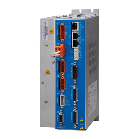
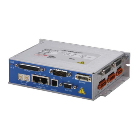
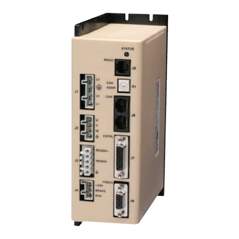
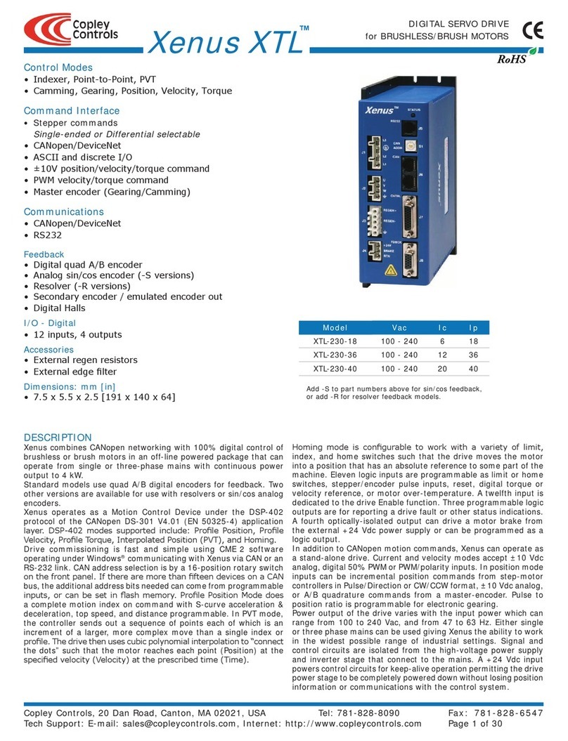
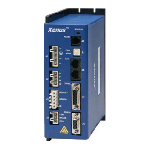
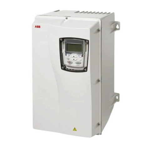
Copley Controls Xenus Plus XP2 Series User manual

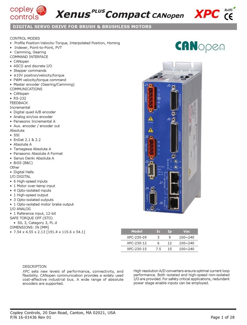
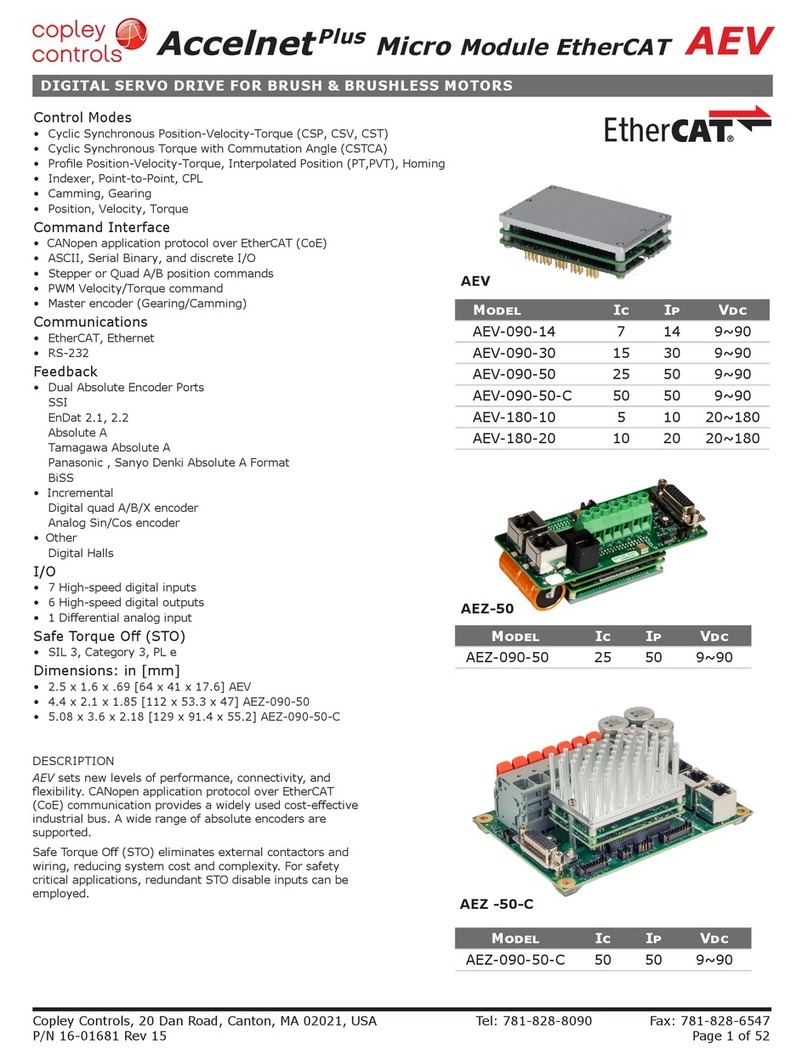
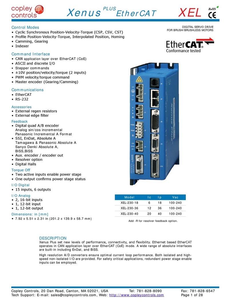
Model Vac Ic Ip
XP2-230-20 100~240 10 20
Add -R to model number for resolver option
Copley Controls, 20 Dan Road, Canton, MA 02021, USA Tel: 781-828-8090 Fax: 781-828-6547
RoHS
Xenus
PLUS 2-Axis CANopen
XP2
Rev 01
DIGITAL SERVO DRIVE FOR BRUSH & BRUSHLESS MOTORS
DESCRIPTION
XP2 sets new levels of performance, connectivity, and
CANopen communication provides a widely used
cost-effective industrial bus. A wide range of absolute
encoders are supported.
High resolution A/D converters ensure optimal current loop
performance. Both isolated and high-speed non-isolated I/O are
provided. For safety critical applications, redundant power stage
enable inputs can be employed.
CONTROL MODES
COMMAND INTERFACE
COMMUNICATIONS
FEEDBACK
Incremental
Absolute
Other
DIMENSIONS: IN [MM]

Copley Controls, 20 Dan Road, Canton, MA 02021, USA Tel: 781-828-8090 Fax: 781-828-6547
RoHS
Xenus
PLUS 2-Axis CANopen
XP2
Rev 01
MODEL XP2-230-20
INPUT POWER
Mains current 20 Arms
Sampling r
Bus voltage compensation Changes in bus or mains voltage do not affect bandwidth
Minimum load inductance
Distributed Control Modes
Stand-alone mode
PWM minimum pulse width 220 ns
ASCII RS-232, 9600~115,200 Baud, 3-wire, RJ-12 connector
Number 22
Ω
Number 4
Ωinput impedance, 14-bit resolution
Ω
Function PWM outputs are inactive and current to the motor will not be possible when the STO function is asserted
Standard Designed to IEC-61508-1, IEC-61508-2, IEC-61800-5-2, ISO-13849-1
Safety Integrity Level SIL 3, Category 3, Performance level d
Inputs 2 two-terminal: STO-IN1+,STO-IN1-, STO-IN2+, STO-IN2-
Number 7
RS-232 PORT
Mode Full-duplex, DTE serial communication port for drive setup and control, 9,600 to 115,200 baud
Protocol Binary and ASCII formats
CAN PORT
Address selection 16 position rotary switch on front panel with 3 additional address bits available as
STATUS INDICATOR LEDS
GENERAL SPECIFICATIONS
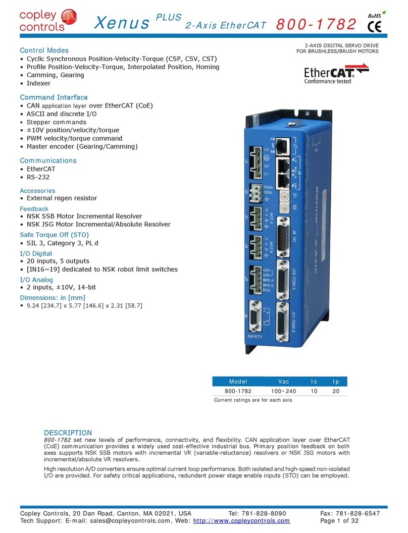
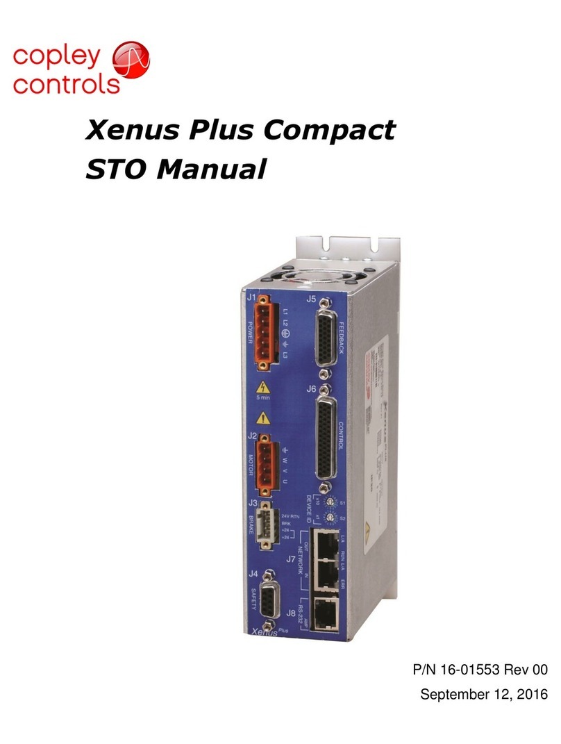
RoHS
Copley Controls, 20 Dan Road, Canton, MA 02021, USA Tel: 781-828-8090 Fax: 781-828-6547
RoHS
Xenus
PLUS 2-Axis CANopen
XP2
Rev 01
GENERAL SPECIFICATIONS
PROTECTIONS
Short circuits Output to output, output to ground, internal PWM bridge faults
I2
9.24 [234.7] x 5.42 [137.6] x 3.59 [91.1] in[mm]
Ambient temperature 0 to +40 °C operating, -40 to +85 °C storage
Contaminants Pollution degree 2
g
g, 10 ms, half-sine pulse, IEC60068-2-27
Environment IEC68-2: 1990
Approvals
Functional Safety
Electrical Safety
UL 61800-5-1-2012
EMC Directive 2004/108/EC – EMC:
IEC 61800-3:2004+A1:2011
FEEDBACK
Incremental:
Absolute:
Absolute A, Tamagawa Absolute A, Panasonic Absolute A Format
status data for encoder operating conditions and errors
Type Digital, single-ended, 120° electrical phase difference
Ω
MULTI-MODE ENCODER PORT
Ωterminating resistors
from analog sin/cos encoders or absolute encoders
A, /A, B, /B, X, /X, from MAX3032 differential line driver
ENCODER POWER SUPPLIES
Number 2

Copley Controls, 20 Dan Road, Canton, MA 02021, USA Tel: 781-828-8090 Fax: 781-828-6547
RoHS
Xenus
PLUS 2-Axis CANopen
XP2
Rev 01
Note!
help you get the best results when using Copley Controls products.
FEEDBACK
Incremental:
Absolute:
status data for encoder operating conditions and errors
Ω
MULTI-MODE ENCODER PORT
Ωterminating resistors
from analog sin/cos encoders or resolvers.
A, /A, B, /B, X, /X, from MAX3032 differential line driver
Type Brushless, single-speed, 1:1 to 2:1 programmable transformation ratio
Reference maximum current 100 mA
Maximum RPM 10,000+
GENERAL SPECIFICATIONS

S1 S2
HEX DEC
000
1 16 1
2 32 2
3 48 3
4 64 4
5 80 5
6 96 6
7 112 7
8
Not
Used
for
CAN
Addr
8
9 9
A 10
B 11
C 12
D 13
E 14
F 15
CAN Status LED
J7
6
9
1
5
D-Sub 9F
33
22
1
8
CAN_L
CAN_GND
CAN_H
CAN_L
RJ-45
CAN_GND
CAN_H
71
J7
Pin 8Pin 1
S2
S1
X1X10
DEVICE ID
Copley Controls, 20 Dan Road, Canton, MA 02021, USA Tel: 781-828-8090 Fax: 781-828-6547
RoHS
Xenus
PLUS 2-Axis CANopen
XP2
Rev 01
CAN NETWORK NODE-ID (ADDRESS)
CANOPEN COMMUNICATIONS
Before installing the drive in a CAN system, it must be assigned a CAN address. A maximum of 127 CAN nodes are allowed on a single
CAN bus. The rotary switch on the front panel controls the four lower bits of the seven-bit CAN address. When the number of nodes on
a bus is less than sixteen, the CAN address can be set using only the switch.
For more information on CANopen communications, download the CANopen Manual from the Copley web-site:
http://www.copleycontrols.com/motion/downloads/pdf/CANopenProgrammersManual.pdf
CAN STATUS LED
CANOPEN CONNECTORS
Dual RJ-45 connectors that accept standard Ethernet
cables are provided for CAN bus connectivity. Pins
are wired-through so that drives can be daisy-
chained and controlled with a single connection
should be placed in the last drive in the chain.
that plugs into a CAN controller and has an RJ-45
XP2-NK CAN CONNECTOR KIT
J7 CAN CONNECTIONS
Note: Red & green led on-times do not
overlap. LED color may be red, green, off,
or ashing of either color.
A bi-color LED gives the state of the CAN connection in
layer.
During a reset condition, the green LED will be off.
the right.
master. In the XPL, the node address is provided by two 16-position rotary switches with hexadecimal
decimal values of the hex settings of each switch.
Example: S1 = 5, S2 = B
Node-ID = 80 + 11 = 91
Example: Node-ID = 91
X1X16

PIN
2 RxD
3,4
5Txd
RoHS
Xenus
PLUS 2-Axis CANopen
XP2
Rev 01
Copley Controls, 20 Dan Road, Canton, MA 02021, USA Tel: 781-828-8090 Fax: 781-828-6547
RS-232 MULTI-DROP
over a single RS-232 port by daisy-chaining a master drive to other drives using CAN cables. In the CAN protocol, address 0 is reserved
address is set to 0, it acts as a CAN master, converting the RS-232 data into CAN messages and passing it along to the other drives
which act as CAN nodes.
CANopen
RS-232
CANopen
CAN Addr 0
CAN Master CAN Node CAN Node
CAN Addr 1 CAN Addr n
6
9
1
5
32
TxD RxD
RJ-11
on
Servo
Drive
RJ-11 cable
6P6C
Straight-wired
53
Gnd Gnd
RxD TxD
25
D-Sub 9F
Dsub-9F
to RJ11
Adapter
1
6
ASCII COMMUNICATIONS
The Copley ASCII Interface is a set of ASCII format commands that can be used to operate and monitor Copley Controls Accelnet,
been programmed using CME 2, a control program can use the ASCII Interface to:
variables.
J6: RS-232 PORT
RJ-11 receptacle,
6 position, 4 contact
XP2
XP2 RS-232 port are through J7, an RJ-11 connector. The XP2 Serial Cable Kit
SER-CK SERIAL CABLE KIT
The SER-CK provides connectivity between a D-Sub 9 male connector and the RJ-11
port of a PC and uses common modular cable to connect to the XP2. The connections
are shown in the diagram below.
placing your order for an XP2!
COMMUNICATIONS: RS-232 SERIAL
ASCII COMMUNICATION PROTOCOL

PIN PIN
1 6
2 7
3 8 STO-PWR
4 9
5
The information provided in the Xenus Plus Dual-Axis STO User Manual must be
1695
Frame Ground
STO-Bypass (6.5 mA)
*XE2 and XEL-XPL STO bypass connections are different.
The diode shown should be used if XE2 and XEL-XPL drives are used on the same
equipment. Otherwise, the diode may be replaced by a jumper.
XE2 STO bypass connectors are not compatible with XEL-XPL drives.
STO-Gnd (Sgnd)
J6
Xenus Plus Dual-Axis
Bypass Plug Connections
Jumper pins:
2-4, 3-5, 6-8, 7-9 *
STO-IN1+
STO-IN2+
STO-IN2-
STO-IN1-
STO-IN1+
STO-IN1-
2
3
1
4
5
6
7
8
9
Upper IGBT Gate Drive
PWM Signals
Buffer
Voltage
Regulator
EN
+HV
PWM
Outputs
+VI
+VI
V_in
+VI Lower IGBT Gate Drive
*
1695
SAFETY
INSTALLATION
Copley Controls, 20 Dan Road, Canton, MA 02021, USA Tel: 781-828-8090 Fax: 781-828-6547
RoHS
Xenus
PLUS 2-Axis CANopen
XP2
Rev 01
SAFE TORQUE OFF (STO)
DESCRIPTION
the upper and lower devices in the PWM outputs from being operated by the digital control core. This provides a positive OFF capability that cannot be
the control core will be able to control the on/off state of the PWM outputs.
XPL models are different. If both drives are
installed in the same cabinet, the diode should
be wired as shown to prevent damage that could
occur if the STO bypass connectors are installed
STO bypass on the XP2 and can be replaced by a
wire between pins 7 and 9.
from an internal current-source. When this is done the STO feature is overridden and control of the output PWM stage is under control of the digital
control core.

Signal Axis A Axis B
Pls, Enc A J12-10 J12-15
Dir, Enc B J12-11 J12-30
Sgnd J12-6,16,22,31,37,44
Shld J12-1
Signal Axis A Axis B
Pls, Enc A J12-8 J12-13
/Pls, Enc /A J12-9 J12-14
Dir, Enc B J12-10 J12-15
/Dir, Enc /B J12-11 J12-30
Sgnd J12-6,16,22,31,37,44
Shld J12-1
Signal Axis A Axis B
PWM J12-10 J12-15
Dir J12-11 J12-30
Sgnd J12-6,16,22,31,37,44
Shld J12-1
Signal Axis A Axis B
PWM J12-8 J12-13
/PWM J12-9 J12-14
Dir J12-10 J12-15
/Dir J12-11 J12-30
Sgnd J12-6,16,22,31,37,44
Shld J12-1
Copley Controls, 20 Dan Road, Canton, MA 02021, USA Tel: 781-828-8090 Fax: 781-828-6547
RoHS
Xenus
PLUS 2-Axis CANopen
XP2
Rev 01
HIGH SPEED INPUTS: IN2, IN3, IN4, IN5, IN12, IN13, IN14, IN15
COMMAND DIFFERENTIAL
Digital position commands can be in either single-ended or differential format. Single-ended signals should be sourced from devices with active pull-up
Ωline-terminators.
DIFFERENTIAL CU/CD
QUAD A/B ENCODER DIFFERENTIAL
Pulse
Direction
IN4(14)
IN5(15)
Enc. A
Enc. B
IN4(14)
IN5(15)
Encoder ph. B
Encoder ph. A
PULSE+
PULSE-
DIRECTION-
DIRECTION+
IN2(12)
IN3(13)
IN4(14)
IN5(15)
Enc. A
Enc. /A
Enc B
Enc /B
Encoder ph. B
Encoder ph. A IN2(12)
IN3(13)
IN4(14)
IN5(15)
PULSE+
PULSE-
DIRECTION+
DIRECTION-
CD (Count-Down)
CU (Count-Up) IN2(12)
IN3(13)
IN4(14)
IN5(15)
CU
CD
IN4(14)
IN5(15)
CU (Count-Up)
CD (Count-Down)
COMMAND DIFFERENTIAL
Duty = 0~100% Current or
Velocity
Polarity or
Direction
IN4(14)
IN5(15)
Current or
Velocity
No function
IN4(14)
IN5(15)
Duty = 50% ±50%
<no connection>
Duty = 0 - 100%
PWM+
PWM-
Direction+
Direction-
IN2(12)
IN3(13)
IN4(14)
IN5(15)
Curr/Vel+
Curr/Vel-
Duty = 50% ±50%
No
Function
<no connection>
IN2(12)
IN3(13)
IN4(14)
IN5(15)

Signal Axis A Axis B
Enc A J12-36 J12-42
Enc /A J12-21 J12-27
Enc B J12-35 J12-41
Enc /B J12-20 J12-26
Enc X J12-34 J12-40
Enc /X J12-19 J12-25
Sgnd J12-6,16,22,31,37,44
Shld J12-1
Signal Axis A Axis B
Pls, Enc A J12-36 J12-42
/Pls, Enc /A J12-21 J12-27
Dir, Enc B J12-35 J12-41
/Dir, Enc /B J12-20 J12-26
Enc X J12-34 J12-40
Enc /X J12-19 J12-25
Sgnd J12-6,16,22,31,37,44
Shld J12-1
+5V output @ 500 mA
Signal Ground
Enc. B
Enc. X
Enc. X
Enc. X
Enc. S
Enc. S
B
X
/X
/S
Enc. A
Incremental
Encoder
Absolute
Encoder
J12 Multi-Port
Frame Ground
A
S
/B
/A
Input/Output
Select
MAX3097
MAX3032
A/B/X signals from
digital encoder
Input/Output
Select
MAX3097
MAX3032
A/B/X signals from
digital encoder
Input/Output
Select
MAX3097
MAX3032
Pulse/Dir or CU/CD
differential commands
Input/Output
Select
MAX3032
S
S
2-Wire digital absolute
encoder signals
Copley Controls, 20 Dan Road, Canton, MA 02021, USA Tel: 781-828-8090 Fax: 781-828-6547
RoHS
Xenus
PLUS 2-Axis CANopen
XP2
Rev 01
MULTI-MODE ENCODER PORT AS AN INPUT
COMMAND INPUT
MULTI-PORT
EMULATED QUAD A/B/X
MULTI-PORT
POSITION COMMAND INPUTS: DIFFERENTIAL
CURRENT or
Quad A/B/X incremental encoder
Quad A/B emulated encoder from sin/cos encoder
receives Data from the encoder in half-duplex mode.
which initiates data transmission from the encoder
on the S-channel in full-duplex mode
INPUT TYPES

Input Pin R1 R2 C1
J12-7 100p +24
J12-8
100p +12
J12-9
J12-10
J12-11
IN6 J9-2
Opto
IN7 J9-3
IN8 J9-4
IN9 J9-5
ICOM1 J9-6
IN10 J10-7 33n +24
IN21 J10-24 100p
Input Pin R1 R2 C1
J12-12 100p +24
J12-13
100p +12
J12-14
J12-15
J12-30
IN16 J9-7
Opto
IN17 J9-8
IN18 J9-9
IN19 J9-18
ICOM2 J9-17
IN20 J11-7 33n +24
IN22 J11-24 100p
Input Pin PU/PD Input Pin PU/PD
IN1 J12-7 1 IN11 J12-12 5
IN2 J12-8 2 IN12 J12-13 6
IN3 J12-9 3 IN13 J12-14 7
IN4 J12-10 4IN14 J12-15 8
IN5 J12-11 IN15 J12-30
S.E.
Input
Diff
Input Pin S.E.
Input
Diff
Input Pin
IN2 IN2+ J12-8 IN12 IN12+ J12-13
IN3 IN2- J12-9 IN13 IN12- J12-14
IN4 IN4+ J12-10 IN14 IN14+ J12-15
IN5 IN4- J12-11 IN15 IN14- J12-30
12V
+
100 pF
2.5V
MAX3096
MAX3096
[IN2,4,12,14]
J12 Control
100 pF
1k
[IN3,5,13,15]
10k
+5V
1k
+
10k
+5V
12V
+
100 pF
[IN2,4,12,14]
J12 Control
100 pF
1k
[IN3,5,13,15]
10k
+5V
1k
10k
+5V
MAX3096
100p
10k
10k 74HC14
[IN1]
[IN2]
[IN15]
A
+5.0 V
100p
10k
10k 74HC14
PullUp = 5V
PullDown = 0V
[INx]
+5V
Copley Controls, 20 Dan Road, Canton, MA 02021, USA Tel: 781-828-8090 Fax: 781-828-6547
RoHS
Xenus
PLUS 2-Axis CANopen
XP2
Rev 01
HS Inputs [IN1~2]
The input resistor of these inputs is programmable to pull-up to
Six of the inputs have individually settable PU/PD.
The other four have PU/PD control for pairs of inputs.
or Camming modes
DIFFERENTIAL
GENERAL PURPOSE INPUTS

Signal Pins Signal Pins
IN6 J9-2 IN16 J9-7
IN7 J9-3 IN17 J9-8
IN8 J9-4 IN18 J9-9
IN9 J9-5 IN19 J9-18
COMM1 J9-6 COMM2 J9-17
J9
4.99k 5.1V
[IN16] 4.7k
4.7k
4.7k
4.7k
[COMM2]
17
7
4.99k 5.1V
[IN17]
8
4.99k 5.1V
[IN18]
9
4.99k 5.1V
[IN19]
18
+
24V
24V GND
+
24V
J9
+
24V
24V GND
4.99k 5.1V
[IN6] 4.7k
4.7k
4.7k
4.7k
[COMM1]
6
2
4.99k 5.1V
[IN7]
3
4.99k 5.1V
[IN8]
4
4.99k 5.1V
[IN9]
5
+
24V
Copley Controls, 20 Dan Road, Canton, MA 02021, USA Tel: 781-828-8090 Fax: 781-828-6547
RoHS
Xenus
PLUS 2-Axis CANopen
XP2
Rev 01
connections. Connect the COMM to controller ground/common
[IN16~19][IN6~9]
OPTO-ISOLATED INPUTS: IN6, IN7, IN8, IN9, IN16, IN17, IN18, IN19

Signal Axis A Axis B
J12-3 J12-5
J12-2 J12-4
Sgnd J12-6,16,22,31,37,44
Shield J12-1
ISOLATED GENERAL PURPOSE OUTPUTS OUT1~5
Input State Condition
OUT1~5 HI
LO
Signal Pins Signal Pins
[OUT1+] J9-19 [OUT1-] J9-10
[OUT2+] J9-20 [OUT2-] J9-11
[OUT3+] J9-21 [OUT3-] J9-12
[OUT4+] J9-22 [OUT4-] J9-13
[OUT5+] J9-23 [OUT5-] J9-14
3
2
1
+
1.5V
Frame Ground
AIN1+
AIN2+
AIN1-
AIN2-
Vref
J12
D/A
F.G.
±10V
±10V
-
5
4
6
+
1.5V
Vref
Sgnd
-
Turnoff
Circuit
[OUTn-]
300mA
max
* at 24 Vdc
Vdc
J9
[OUTn+]
20
60Ω
min*
36V
ASSR-1218
+
Copley Controls, 20 Dan Road, Canton, MA 02021, USA Tel: 781-828-8090 Fax: 781-828-6547
RoHS
Xenus
PLUS 2-Axis CANopen
XP2
Rev 01
from a controller. If not used as command inputs, they can be used as
general-purpose analog inputs.
[AIN A,B]
ANALOG INPUTS
HI/LO DEFINITIONS: [OUT1~5]

HI/LO DEFINITIONS: OUTPUTS
Input State Condition
BRK-A,B
OUT6,7
HI
Output transistor is OFF
Motor cannot move
LO
Output transistor is ON
Motor is free to move
SPECIFICATIONS
Output Data Notes
Max
Output Current Ids 1.0 Adc
CONNECTIONS
Pin Signal
5
4
3
2
1
J5
B Brk
A Brk
Axis A
Brake
Axis B
Brake
5
4
24V
+24
+24 *
24V RTN
2
3
1
i
+
0
i
+
0
HV Com
Earth Ground
Heatplate/chassis
Frame Gnd
Frame
Gnd
J1
Control
J8
Mot A
J10
Power
1
2
3
Signal Gnd
Signal Gnd
Signal Gnd
Signal Gnd
Signal Gnd
Signal Gnd
Signal Gnd
Signal Gnd
J5
Serial 3
4
1
1
37
44
31
16
6
22
J9
Mot B
1
J2
I/O J3
Brake
1
+HV
0V
+Aux
0V
Earthing connections for power supplies should be as close as possible to elimimate
potential differences between power supply 0V terminals.
Brk 24V Input
Brk 24V Output
5
4
2
3
1
Brake B
Brake A
24V Return
24V
Copley Controls, 20 Dan Road, Canton, MA 02021, USA Tel: 781-828-8090 Fax: 781-828-6547
RoHS
Xenus
PLUS 2-Axis CANopen
XP2
Rev 01
ISOLATED BRAKE OUTPUTS
Programmable functions
Brake is Active
Motor cannot move
CME2 I/O Line States shows Output 6 or 7 as HI
Servo drive is disabled, PWM outputs are off
Brake is Inactive
Motor can move
CME2 I/O Line States shows Output 6 or 7 as LO
Servo drive is enabled, PWM outputs are on
all drive circuits and frame ground.

MOTOR CONNECTIONS: ENCODER & RESOLVER
Signal J10,J11
Pin
Enc A 13
Enc /A 12
Enc B 11
Enc /B 10
Enc X 9
Enc /X 8
6
Sgnd 5
Shld 1
Signal J10,J11
Pin
19
18
21
20
23
22
17
Sgnd 16
Shld 1
Signal J10,J11
Pin
19
18
21
20
23
22
17
Sgnd 16
Shld 1
+5V Out @ 500 mA
Signal Ground
Sin(+)
Sin(-)
Cos(+)
Cos(-)
Idx(+)
Idx(-)
-
+
-
+
10k
121
J10, J11
10k
121
Encoder
FG
sin
cos
+5V
0V
121
indx
Frame Ground
10k
Sin
Cos
Indx
10k
1k
1k
+5V
1k
Encoder J10, J11
FG Frame Ground
Enc. A
121
A
Enc. B
121
B
Enc. Index
130
Z/X
X
/B
B
/A
A
+5V
0V
+5V Out @ 500 mA
Signal Ground
1k +5V
Z
Enc. A
Enc. B
Enc. Index
A
/A
B
/B
X
/X
1k
1k
+5V
Encoder
121
121
130
FG Frame Ground
A
B
+5V
0V
+5V Out @ 500 mA
Signal Ground
J10, J11
Resolver
FG Frame Ground
J10, J11
Sin(+) S3
Sin(-) S1
Cos(-) S4
Cos(+) S2
Ref(+) R1
Ref(-) R2
R/D
Conversion
Sin
S3 S1
S2
S4
R1R2
Cos
Ref
Signal Ground
Copley Controls, 20 Dan Road, Canton, MA 02021, USA Tel: 781-828-8090 Fax: 781-828-6547
RoHS
Xenus
PLUS 2-Axis CANopen
XP2
Rev 01
QUAD A/B ENCODER WITH FAULT PROTECTION
protections for the following conditions:
Short-circuits line-line:
Open-circuit condition: The 121Ω
This will produce the same fault condition as a short-circuit across the inputs.
Low differential voltage detection:
±15kV ESD protection: The 3097E has protection against high-voltage discharges using the Human Body Model.
Extended common-mode range:
drive the motor to produce motion. A thermal sensor that indicates motor overtemperature is used to shut down the drive to protect the
incremental encoders with analog outputs, or with ServoTube
motors.
Resolver set up, motor phasing, and other commissioning
CONNECTIONS WITH A/B/X ENCODER
SHIELDED CABLE CONNECTIONS
Double-shielded cable is recommended for resolvers and analog sin/cos encoders. The outer shield connects to the motor and drive
encoders, but the connections are shown here and on following pages for completeness.

Signal J10,J11
Pin
9
8
Data 15
/Data 14
6,17
Sgnd 5,16
Shld 1
Signal J10,J11
Pin
9
8
Data 15
/Data 14
19
18
21
20
6,17
Sgnd 5,16
Shld 1
Signal J10,J11
Pin
Data 15
/Data 14
6,17
Sgnd 5,16
Shld 1
Encoder
221
130
Clk
/Clk
Dat
/Dat
FG Frame Ground
J10, J11
Clk
Data
Data
Clk
+5V
0V
+5V Out @ 500 mA
A
A
B
B
Signal Ground
BiSS
Encoder
221
130
MA+
MA-
SL+
SL-
FG Frame Ground
J10, J11
Clk
Data
Master
Slave
V+
V-
+5V Out @ 500 mA
Signal Ground
-
+
-
+
A
B
A
B
Encoder
221
Sin(+)
Sin(-)
Cos(+)
Cos(-)
Dat
/Dat
Clk
/Clk 130
FG Frame Ground
J10, J11
Clk
Data
Data
Clk
+5V
0V
+5V Out @ 500 mA
Signal Ground
10k
10k
121 Sin
Cos
10k
10k
121
sin
cos
Absolute-A
Encoder
SD+
SD-
0V
+5V
J10, J11
V+
V-
+5V Out
@ 500 mA
Signal Ground
Cmd
D-R
SD
Frame
Ground
Cmd
D-R
SD
MAX3362B
1.2k
1.2k
220
5V
Dat
/Dat
Copley Controls, 20 Dan Road, Canton, MA 02021, USA Tel: 781-828-8090 Fax: 781-828-6547
RoHS
Xenus
PLUS 2-Axis CANopen
XP2
Rev 01
SSI ABSOLUTE ENCODER
connect an absolute position encoder to a motion controller or control
format to the encoder which initiates the transmission of the position
encoder data bits and counts per motor revolution are programmable.
The hardware bus consists of two signals: SCLK and SDATA. Data is sent in
ENDAT ABSOLUTE ENCODER
The EnDat interface is a Heidenhain interface that is similar to SSI in the use
from the same encoder. The number of position data bits is programmable as
is the use of sin/cos channels. Use of sin/cos incremental signals is optional
BiSS ABSOLUTE ENCODER
BiSS is an - Open Source - digital interface for sensors and actuators.
additional options.
Serial Synchronous Data Communication
Cyclic at high speed
Line delay compensation for high speed data transfer
Safety capable: CRC, Errors, Warnings
Bus capability incl. actuators
Bidirectional
BiSS B-protocol: Mode choice at each cycle start
BiSS C-protocol: Continuous mode
ABSOLUTE-A ENCODER
The Absolute A interface is a serial, half-duplex type that is
electrically the same as RS-485
SSI,Bi
MOTOR CONNECTIONS: ABSOLUTE ENCODERS

MOTOR CONNECTIONS: MOTOR, HALLS, OVERTEMP
Signal Pin
Motemp A J10-7
Motemp B J11-7
Sgnd J10,J11
-5,16,25,26
Property Ohms
Resistance in the temperature range
20°C to +70°C 60~750
Resistance at 85°C
Resistance at 95°C
Resistance at 105°C
Signal J3,J4
Pin
Mot U 4
3
Mot W 2
Shield 1
Signal J10,J11
Pin
Hall U 1
2
Hall W 3
6,17
Sgnd 5,16
25,26
+5V
Motemp
Thermistor,
Posistor,
or switch Signal Gnd
4.99k
10k
33n
J10,J11
Grounding
tab
J3,J4
F.G.
PWM
+HV
0V
+
W
V
U
Motor
3 ph.
Halls
+5V Out @ 500 mA
Signal Ground
+5V
0V
10K
100p
10K
Hall U +5V
J10,J11
100p
10K
10K
Hall V +5V
100p
10K
10K
Hall W
+5V
Hall A
Hall B
Hall C
Copley Controls, 20 Dan Road, Canton, MA 02021, USA Tel: 781-828-8090 Fax: 781-828-6547
RoHS
Xenus
PLUS 2-Axis CANopen
XP2
Rev 01
MOTOR PHASE CONNECTIONS
The drive output is a three-phase PWM inverter
three sinusoidal voltage waveforms that drive
the continuous current rating of the motor. Motor
cabling should use twisted, shielded conductors for
into other circuits. The motor cable shield should
connect to motor frame and the drive frame ground
Hall signals are single-ended signals that provide
may be sourced by magnetic sensors in the motor,
encoder disc. They typically operate at much lower
has switched to sinusoidal commutation.
condition. The active level is programmable.

Signal Axis A
Pin Axis B
Pin
Enc A J12-36 J12-42
Enc /A J12-21 J12-27
Enc B J12-35 J12-41
Enc /B J12-20 J12-26
Enc X J12-34 J12-40
Enc /X J12-19 J12-25
32,17 J12-38,23
Sgnd J12-31,16 J12-37,22
Shld J12-1
Signal Axis A
Pin Axis B
Pin
J12-34 J12-40
J12-19 J12-25
Dat, SL+ J12-33 J12-39
/Dat, SL- J12-18 J12-24
J12-32,17 J12-38,23
Sgnd J12-31,16 J12-37,22
Shld J12-1
Signal Axis A
Pin Axis B
Pin
Dat J12-33 J12-39
/Dat J12-18 J12-24
J12-32,17 J12-38,23
Sgnd J12-31,16 J12-37,22
Shld J12-1
Input/Output
Select
MAX3097
MAX3032
A/B/X signals from
digital encoder
221
MA+
MA-
SL+
SL-
FG Frame Ground
J12
Full-duplex
Absolute encoder
Clk
Data
Master
Slave
V+
V-
+5V Out @ 500 mA
Signal Ground
130
1k +5V
1k
Half-duplex
Absolute encoder
1.2k
1.2k
220
5V
SD+
SD-
0V
+5V
J12
V+
V-
+5V Out
@ 500 mA
Dat
/Dat
Signal Ground
Cmd
D-R
SD
Cmd
D-R
SD
MAX3362B
Frame
Ground
-
Input/Output
Select
MAX3097
MAX3032
Data & Clk signals from
absolute encoder
Copley Controls, 20 Dan Road, Canton, MA 02021, USA Tel: 781-828-8090 Fax: 781-828-6547
RoHS
Xenus
PLUS 2-Axis CANopen
XP2
Rev 01
FEEDBACK FROM ABSOLUTE ENCODERS
encoder can come from absolute encoders, too.
Analog sin/cos and index signals are not supported
by the multi-port. The graphic to the right shows
half-duplex format but both full and half-duplex
FULL-DUPLEX ENCODERS
SSI
BiSS
EnDat
HALF-DUPLEX ENCODERS
Absolute-A
Tamagawa Absolute-A
EMULATED QUAD A/B/X
MULTI-PORT
FULL-DUPLEX
HALF-DUPLEX
ABSOLUTE ENCODER, FULL-DUPLEX MODE
ABSOLUTE ENCODER, HALF-DUPLEX MODE
When operating in position mode the multi-mode port
can accept digital command signals from external
encoders. These can be used to drive cam tables, or
as master-encoder signals when operating in a master/
MULTI-MODE ENCODER PORT

Signal Axis A
Pin Axis B
Pin
Enc A Pulse CW J12-36 J12-42
Enc /A /Pulse /CW J12-21 J12-27
Enc B Dir CCW J12-35 J12-41
Enc /B /Dir /CCW J12-20 J12-26
Enc X J12-34 J12-40
Enc /X J12-19 J12-25
32,17 J12-38,23
Sgnd J12-31,16 J12-37,22
J12-1
Signal Axis A
Pin Axis B
Pin
Enc A J12-36 J12-42
Enc /A J12-21 J12-27
Enc B J12-35 J12-41
Enc /B J12-20 J12-26
Enc X J12-34 J12-40
Enc /X J12-19 J12-25
32,17 J12-38,23
Sgnd J12-31,16 J12-37,22
J12-1
Secondary
Encoder Input
Input/Output
Select
Quad A/B/X primary
encoder
MAX3032
MAX3097
Buffered A/B/X signals
from primary encoder
Secondary
Encoder Input
Input/Output
Select
MAX3032
MAX3097
Emulated Quad A/B
signals from
analog Sin/Cos encoder
or resolver
Emulated A/B signals
Input/Output
Select
MAX3097
MAX3032
A/B/X signals from
digital encoder
Input/Output
Select
MAX3097
MAX3032
Pulse/Dir or CU/CD
differential commands
Copley Controls, 20 Dan Road, Canton, MA 02021, USA Tel: 781-828-8090 Fax: 781-828-6547
RoHS
Xenus
PLUS 2-Axis CANopen
XP2
Rev 01
the A/B/X signals drive the multi-mode port output
buffers directly. This is useful in systems that use
encoder signals because these now come from J12,
to connect to both controller and motor, the buffered
could occur if the motor encoder had to drive two
121 ohm terminating resistor.
AS EMULATED QUAD A/B/X ENCODER OUTPUTS
Analog sin/cos signals are interpolated in the drive with
programmable resolution. The incremental position
format which drives the multi-mode port output
buffers. Some analog encoders also produce a digital
control system.
MULTI-MODE ENCODER PORT: FEEDBACK OUTPUTS
When operating in position mode the multi-
mode port can accept digital command signals
from external encoders. These can be used to
drive cam tables, or as master-encoder signals
DIRECTION, PULSE-UP/PULSE-DOWN, OR
The multi-mode port can also be used when
digital command signals are in a differential
format. These are the signals that typically
go to single-ended inputs. But, at higher
signals in which case the multi-mode port
can be used.
MULTI-MODE ENCODER PORT: COMMAND INPUTS
COMMAND INPUTS MULTI-PORT
BUFFERED OUTPUTS MULTI-PORT

Input Pin R1 R2 C1
IN1 J12-7 100p
IN2 J12-8
100p
IN3 J12-9
IN4 J12-10
IN5 J12-11
IN6 J10-2
Opto
IN7 J10-3
IN8 J10-4
IN9 J10-5
ICOM1 J10-6
IN10 J11-7 33n
IN21 J11-24 100p
Input State Condition
IN1,10,21 HI
LO
IN2~5 HI
LO
IN6~9 HI Input diode ON
LO Input diode OFF
Input Pin PU/PD
IN1 J12-7 1
IN2 J12-8 2
IN3 J12-9 3
IN4 J12-10 4
IN5 J12-11
12V
+
100 pF
2.5V
MAX3096
MAX3096
[IN2,4,12,14]
J12 Control
100 pF
1k
[IN3,5,13,15]
10k
+5V
1k
+
10k
+5V
J9
+
24V
24V GND
4.99k 5.1V
[IN6] 4.7k
4.7k
4.7k
4.7k
[COMM1]
6
2
4.99k 5.1V
[IN7]
3
4.99k 5.1V
[IN8]
4
4.99k 5.1V
[IN9]
5
+
24V
100p
10k
10k 74HC14
[INx]
+5V
33n
10k
4.99k 74HC2G14
[INx]
+5V
Copley Controls, 20 Dan Road, Canton, MA 02021, USA Tel: 781-828-8090 Fax: 781-828-6547
RoHS
Xenus
PLUS 2-Axis CANopen
XP2
Rev 01
INPUTS WITH
PULL UP/DOWN
CME2 SCREEN FOR INPUTS [IN1~IN10]
INPUT DATA [IN1]
[IN21]
[IN10]
[IN2~5]
HI/LO DEFINITIONS: INPUTS
or negative input voltages. When voltage is applied
diode of the opto-coupler the diode condition is
ON. When no voltage is applied to an input and no
100p
10k
10k 74HC14
PullUp = 5V
PullDown = 0V
[INx]
+5V
[IN6~9]
CME2 & AXIS A I/O CONNECTIONS

Copley Controls, 20 Dan Road, Canton, MA 02021, USA Tel: 781-828-8090 Fax: 781-828-6547
RoHS
Xenus
PLUS 2-Axis CANopen
XP2
Rev 01
Input Pin R1 R2 C1
IN11 J12-12 100p
IN12 J12-13
100p
IN13 J12-14
IN14 J12-15
IN15 J12-30
IN16 J9-7
Opto
IN17 J9-8
IN18 J9-9
IN19 J9-18
ICOM2 J9-17
IN20 J11-7 33n
IN22 J11-24 100p
Input State Condition
IN11,20,22 HI
LO
IN12~15 HI
LO
IN16~19 HI Input diode ON
LO Input diode OFF
Input Pin PU/PD
IN11 J12-12 5
IN12 J12-13 6
IN13 J12-14 7
IN14 J12-15 8
IN15 J12v-30
INPUTS WITH
PULL UP/DOWN
CME2 SCREEN FOR INPUTS [IN11~IN20]
INPUT DATA [IN11]
[IN22]
[IN20]
[IN12~15]
HI/LO DEFINITIONS: INPUTS
positive or negative input voltages. When voltage
input diode of the opto-coupler the diode condition
is ON. When no voltage is applied to an input and
12V
+
100 pF
2.5V
MAX3096
MAX3096
[IN2,4,12,14]
J12 Control
100 pF
1k
[IN3,5,13,15]
10k
+5V
1k
+
10k
+5V
J9
4.99k 5.1V
[IN16] 4.7k
4.7k
4.7k
4.7k
[COMM2]
17
7
4.99k 5.1V
[IN17]
8
4.99k 5.1V
[IN18]
9
4.99k 5.1V
[IN19]
18
+
24V
24V GND
+
24V
100p
10k
10k 74HC14
PullUp = 5V
PullDown = 0V
[INx]
+5V
100p
10k
10k 74HC14
[INx]
+5V
33n
10k
4.99k 74HC2G14
[INx]
+5V
[IN16~19]
CME2 & AXIS B I/O CONNECTIONS
This manual suits for next models
1
Table of contents
Other Copley Controls Servo Drive manuals

Copley Controls
Copley Controls Xenus Plus Compact User manual

Copley Controls
Copley Controls AccelnetPlus AEV-090-14 User manual

Copley Controls
Copley Controls Accelnet Plus Dual-Axis Panel EtherCAT User manual

Copley Controls
Copley Controls Xenus Plus Series User manual

Copley Controls
Copley Controls Xenus PLUS Compact CANopen Series User manual

Copley Controls
Copley Controls Xenus XTL Series User manual

Copley Controls
Copley Controls Xenus R10 User manual

Copley Controls
Copley Controls Xenus Plus XEL Series User manual

Copley Controls
Copley Controls Xenus PLUS User manual

Copley Controls
Copley Controls Xenus XTL Series User manual