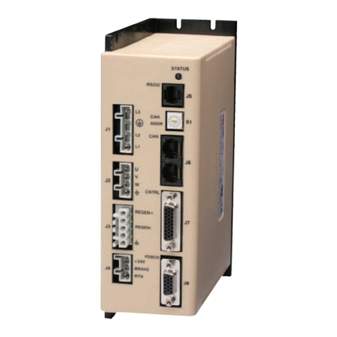
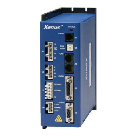
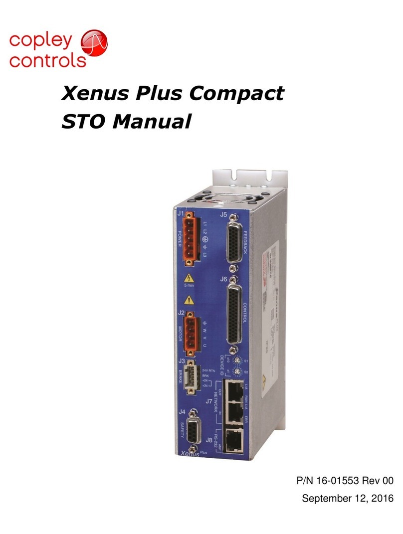
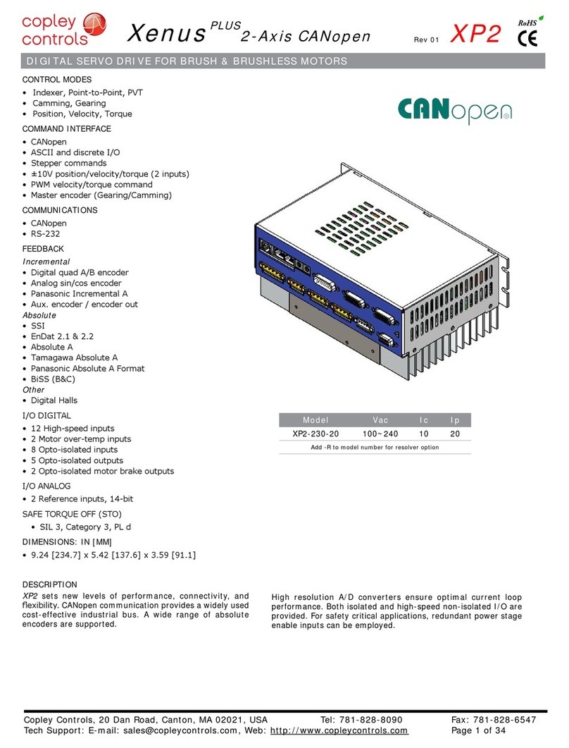
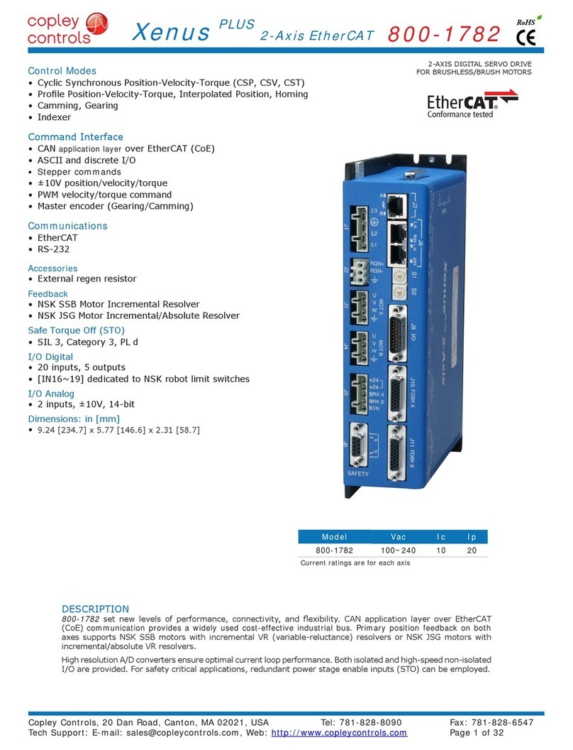
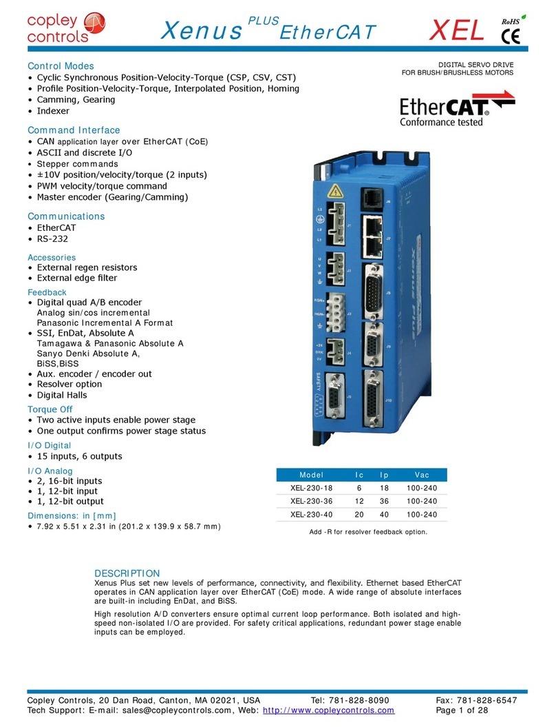
Copley Controls Xenus Plus Series User manual

123123
P/N 16-01344
Revision 06
August 30, 2019
Xenus Plus™
User Guide

Xenus Plus User Guide 16-01344 Rev 06
This page for notes

Xenus Plus User Guide 16-01344 Rev 06
Copley Controls 3
TABLE OF CONTENTS
About This Manual..................................................................................................................................................................................... 5
1: Introduction.................................................................................................................................................................................... 10
1.1: Xenus Plus Family Overview.................................................................................................................................................... 11
1.2: CME.......................................................................................................................................................................................... 12
1.3: CML/CMO................................................................................................................................................................................. 13
1.4: Copley Virtual Machine (CVM) ................................................................................................................................................. 13
1.5: Indexer 2................................................................................................................................................................................... 13
1.6: CPL........................................................................................................................................................................................... 13
2: Operational Theory........................................................................................................................................................................ 14
2.1: Drive Power Architecture.......................................................................................................................................................... 15
2.2: Operating Modes ...................................................................................................................................................................... 17
2.3: Input Command Types ............................................................................................................................................................. 28
2.4: Communication......................................................................................................................................................................... 33
2.5: Status Indicators....................................................................................................................................................................... 38
2.6: Protection.................................................................................................................................................................................. 50
2.7: Position and Velocity Errors...................................................................................................................................................... 52
2.8: Inputs XEL/XPL/XML................................................................................................................................................................ 55
2.9: Inputs XE2/XP2/XM2/800-1818/800-1819/800-1887 ............................................................................................................... 56
2.10: Outputs, XEL/XPL/XML .......................................................................................................................................................... 58
2.11: Outputs, XE2/XP2/XM2/800-1818/800-1819/800-1887 ......................................................................................................... 58
2.12: Brake Operation...................................................................................................................................................................... 58
2.13: Regen Resistor Theory........................................................................................................................................................... 61
3: Specifications ................................................................................................................................................................................ 64
3.1: Agency Approvals..................................................................................................................................................................... 65
3.2: Power Input............................................................................................................................................................................... 65
3.3: Power Output............................................................................................................................................................................ 66
3.4: Control Loops ........................................................................................................................................................................... 67
3.5: Regen Circuit Output (External Regen Resistor)...................................................................................................................... 67
3.6: Regen Circuit Output (Internal Regen Resistor)....................................................................................................................... 67
3.7: Digital Command Inputs ........................................................................................................................................................... 68
3.8: Analog Inputs............................................................................................................................................................................ 68
3.9: Digital Inputs............................................................................................................................................................................. 69
3.10: Analog Output......................................................................................................................................................................... 70
3.11: Digital Outputs ........................................................................................................................................................................ 70
3.12: Encoder Power Outputs.......................................................................................................................................................... 71
3.13: Primary Encoder Inputs .......................................................................................................................................................... 71
3.14: Analog Encoder Inputs ........................................................................................................................................................... 72
3.15: Hall Switch Inputs ................................................................................................................................................................... 73
3.16: Resolver Interface................................................................................................................................................................... 74
3.17: Multi-Mode Port ...................................................................................................................................................................... 75
3.18: Serial Interface........................................................................................................................................................................ 76
3.19: Network Interfaces.................................................................................................................................................................. 77
3.20: Status Indicators..................................................................................................................................................................... 78
3.21: Fault Levels ............................................................................................................................................................................ 78
3.22: Power Dissipation................................................................................................................................................................... 79
3.23: Thermal Impedance................................................................................................................................................................ 79
3.24: Mechanical and Environmental............................................................................................................................................... 80
3.25: Dimensions............................................................................................................................................................................. 81
4: Wiring.............................................................................................................................................................................................. 84
4.1: General Wiring Instructions ...................................................................................................................................................... 85
4.2: AC Mains (J1)........................................................................................................................................................................... 88
4.3: Motor(s) .................................................................................................................................................................................... 91
4.4: Regen Resistor (Optional) ........................................................................................................................................................ 93
4.5: Logic Supply / Brake................................................................................................................................................................. 96
4.6: Ferrules –XE2/XP2/XM2/800-1818/800-1819/800-1887......................................................................................................... 98
Motor Torque Off ............................................................................................................................................................................ 99
4.7: (MTO) ....................................................................................................................................................................................... 99
4.8: Safe Torque Off (STO) ........................................................................................................................................................... 104
4.9: RS-232 Serial Communications.............................................................................................................................................. 106
4.10: Network Ports ....................................................................................................................................................................... 107
4.11: Control I/O ............................................................................................................................................................................ 110
4.12: Motor Feedback.................................................................................................................................................................... 126
A: Regen Resistor Sizing and Configuration................................................................................................................................. 134
A.1: Sizing a Regen Resistor......................................................................................................................................................... 135
B: I2T Time Limit Algorithm................................................................................................................................................................... 139
B.1: I2T Algorithm........................................................................................................................................................................... 140
C: Thermal Considerations.............................................................................................................................................................. 143
C.1: Operating Temperature and Cooling Configurations ............................................................................................................. 144
C.2: Heatsink Mounting Instructions (XEL/XPL/XML).................................................................................................................... 148
Xenus Plus User Guide 16-01344 Rev 06
Copley Controls 4
C.3: Heatsink Mounting Instructions (XE2/XP2/XM2, “-N” and 800-1887 Models) ...................................................................... 149
D: Xenus Plus Filter.......................................................................................................................................................................... 150
D.1: Overview ................................................................................................................................................................................ 151
D.2: XTL-FA-01 Edge Filter Wiring................................................................................................................................................ 154
E: Connecting XPL/XP2 for Serial Control..................................................................................................................................... 157
E.1: Single-Axis and Multi-Drop..................................................................................................................................................... 158
F: Ordering Guide and Accessories............................................................................................................................................... 159
F.1: Drive Model Numbers............................................................................................................................................................. 160
F.2: Accessory Model Numbers..................................................................................................................................................... 163
F.3: Heatsink Kits........................................................................................................................................................................... 164
F.4: External Regen Resistor Assemblies..................................................................................................................................... 165
F.5: Edge Filter .............................................................................................................................................................................. 165
F.6: Order Example ....................................................................................................................................................................... 165
F.7: Copley Standard Regen Resistor Specifications.................................................................................................................... 166

Xenus Plus User Guide 16-01344 Rev 06
Copley Controls 5
ABOUT THIS MANUAL
Title, Number, Revision
Title
The Xenus Plus User Guide
Document Number
16-01344
Current Revision
06
Revision History
Revision
Date
ECO
Comments
AA
December 30, 2014
ECO-056871
Initial Release. Originated from 16-01018 Rev 07
00
March 9, 2015
ECO-056484
Updated PE symbols and clarified mandatory use of
line filters.
01
April 2, 2015
ECO-057985
OVC II Mains Requirement and full address for Mfr
& EU Rep. Add model 800-1818
02
September 18,
2015
ECO-059376
Correct input voltage rating (from 5V to 12V) for
single ended/differential non-isolated digital inputs
03
February 7, 2017
ECO-064419
Allow use of isolation transformer to eliminate need
for SPD and allow drive operation up to 4000m
04
March 17, 2017
ECO-066092
Update to reflect EN 61800-5-2:2007
05
February 1, 2019
ECO- 072319
Update to reflect latest revisions of IEC 61800-5-
1:2016 and IEC 61800-5-2:2016
06
August 26, 2019
ECO-074059
Update to change XEL, XPL, XML STO to MTO to
differentiate from certified STO on XE2, XP2, XM2.
No change to certification of XE2, XP2, XM2.
EC Declaration of Conformity
The products covered by this user guide comply with the applicable EC Directives including
2014/30/EU (EMC Directive) and 2014/35/EU (Low Voltage Directive). Complete EC Declarations
of Conformity are available on the internet at www.copleycontrols.com.
Name and Address of the Manufacturer: Name and Address of the authorized representative:
Analogic Corporation d/b/a Copley Controls BK Medical ApS
20 Dan Road Mileparken 34, DK-2730
Canton, MA 02021 Herlev
USA Denmark
Overview and Scope
This manual describes the operation and installation of the XEL, XE2, XPL, XP2, XML, XM2, 800-
1818, 800-1819 and 800-1887 drives manufactured by Copley Controls. All Xenus Plus products
have serial numbers that incorporate the week and year of production into the first 4 digits (WWYY)
of the serial number.

Xenus Plus User Guide 16-01344 Rev 06
Copley Controls 6
EC Declaration of Conformity
The complete EC Declarations of Conformity for all products are available on the internet at
www.copleycontrols.com.
Original Instructions
This manual is considered to be “original instructions” as defined in EC Directive 2006/42/EC and
the contents have been verified by Copley Controls.

Xenus Plus User Guide 16-01344 Rev 06
Copley Controls 7
Related Documentation
For important setup and operation information, see the CME User Guide (Under Using CME2 here:
http://www.copleycontrols.com/Motion/Downloads/software.html).
Users of the CANopen features should also read these Copley Controls documents:
•CANopen Programmer’s Manual
•CMO (Copley Motion Objects) Programmer’s Guide
•CML Reference Manual
And, this guide for MACRO network users:
•MACRO Network User Guide
Also of related interest:
•Indexer 2 Program User’s Guide (describes use of Indexer Program to create motion
control sequences)
•ASCII Programmer’s Guide (describes how to send ASCII format commands over a
drive’s serial bus to set up and control one or more drives)
•Copley Amplifier Parameter Dictionary
•Copley Camming User Guide
•Copley Controls Serial Encoder Guide
•CPL User Guide
•Xenus Plus Dual-Axis STO Manual
Links to these publications, along with other documents, data sheets and software releases, can
be found at: http://www.copleycontrols.com.
Comments
Copley Controls welcomes your comments on this manual.
For contact information, see http://www.copleycontrols.com.
Copyrights
No part of this document may be reproduced in any form or by any means, electronic or mechanical,
including photocopying, without express written permission of Copley Controls.
Xenus XEL, XE2, XPL, XP2, XML and XM2 are registered trademarks of Copley Controls.
CME is a registered trademark of Copley Controls.
Windows XP, Windows 7, Visual Basic, and .NET are trademarks or registered trademarks
of the Microsoft Corporation.
LabVIEW is a registered trademark of National Instruments.
EtherCAT is a registered trademark and patented technology,
licensed by Beckhoff Automation GmbH, Germany.
Document Validity
We reserve the right to modify our products. The information in this document is subject to change
without notice and does not represent a commitment by Copley Controls.
Copley Controls assumes no responsibility for any errors that may appear in this document.

Xenus Plus User Guide 16-01344 Rev 06
Copley Controls 8
Product Warnings
Observe all relevant state, regional and local safety regulations when installing and using this
product. There are no user serviceable parts in the Xenus Plus servo drives.
Removal of the cover or tampering with internal components will void the warranty
DANGER
DANGER: Hazardous voltages.
Exercise caution when installing and adjusting. Persons responsible for installing and
commissioning Xenus Plus servo drives must be experienced in all aspects of electrical
equipment installations.
Failure to heed this warning can cause equipment damage, injury, or death.
DANGER
Risk of electric shock. Wait 5 minutes after disconnecting mains power
before handling.
High-voltage circuits connected to mains power. After disconnecting mains power, wait 5
minutes before handling drive to allow for discharge of internal DC bus capacitance.
XEL/XPL/XML
J1, J2, J3
XE2/XP2/XM2/800-1818/800-1819/800-1887
J1, J2, J3, and J4
Failure to heed this warning can cause equipment damage, injury, or death.
DANGER
Risk of unexpected motion with non-latched faults.
After the cause of a non-latched fault is corrected, the drive re-enables the PWM output
stage without operator intervention. In this case, motion may re-start unexpectedly.
Configure faults as latched unless a specific situation calls for non-latched behavior. When
using non-latched faults, be sure to safeguard against unexpected motion.
Failure to heed this warning can cause equipment damage, injury, or death.
DANGER
Using CME or serial commands may affect or suspend CANopen operations.
When operating the drive as a CANopen node, the use of CME or ASCII serial commands
may affect CANopen operations in progress. Using such commands to initiate motion may
cause CANopen operations to suspend. CANopen operations may restart unexpectedly
when the commanded motion is stopped.
Failure to heed this warning can cause equipment damage, injury, or death.
DANGER
Latching an output does not eliminate the risk of unexpected motion with
non-latched faults.
Associating a fault with a latched, custom-configured output does not latch the fault itself.
After the cause of a non-latched fault is corrected, the drive re-enables without operator
intervention. In this case, motion may re-start unexpectedly. For more information, see
Clearing Latched Faults (p.51).
Failure to heed this warning can cause equipment damage, injury, or death.
DANGER
Use equipment as described.
Operate drives within the specifications provided in this manual.
Failure to heed this warning can cause equipment damage, injury, or death.
DANGER
Drive heatsink surfaces can exceed 80C and regen resistor surface
can exceed 100C depending on drive use conditions
Do not touch drive heatsink during operation and allow it to cool before handling after
power is removed.
Failure to heed this warning can cause injury
!
!
!
!
!
!
!

Xenus Plus User Guide 16-01344 Rev 06
Copley Controls 9
This page for notes.

Xenus Plus User Guide 16-01344 Rev 06
Copley Controls 10
CHAPTER
1: INTRODUCTION
This chapter provides an overview of the Copley Controls Xenus Plus drives.
Contents include:
1.1: Xenus Plus Family Overview.................................................................................................................................................... 11
1.2: CME.......................................................................................................................................................................................... 12
1.3: CML/CMO................................................................................................................................................................................. 13
1.4: Copley Virtual Machine (CVM) ................................................................................................................................................. 13
1.5: Indexer 2................................................................................................................................................................................... 13
1.6: CPL........................................................................................................................................................................................... 13

Xenus Plus User Guide 16-01344 Rev 06
Copley Controls 11
1.1: Xenus Plus Family Overview
Each Xenus Plus servo drive provides 100% digital control of brushless or brush motors in an off-
line powered package. Xenus Plus can operate from single or three-phase mains with a continuous
power output of up to 4 kW.
Xenus Plus comes in six basic models to support three network interface protocols: single axis XEL
and dual axis XE2, which support CANopen over EtherCAT, the single axis XML and dual axis XM2,
which support MACRO, and single axis XPL and dual axis XP2, which support CANopen.
The XE2, XP2, and XM2 models have the Safe Torque Off (STO) function. Two inputs are provided
which, when de-energized, prevent the upper and lower devices in the PWM outputs from being
operated by the digital control core. This provides a positive OFF capability that cannot be overridden
by the control firmware, or associated hardware components. When both inputs are energized, the
control core will be able to control the on/off state of the PWM outputs. The STO feature in these
models was developed in accordance with several functional safety standards and has both SIL and
Category/Performance Level ratings. For more information on STO for the Xenus Plus Dual Axis
models, see the Xenus Plus Dual-Axis STO Manual
The XEL, XPL, and XML models have the Motor Torque Off (MTO) feature. The MTO circuit in these
models was designed using guidance from IEC 61800-5-2, an international standard that specifies
requirements for motor drive functional safety features including STO. It operates in the same way
as STO but does not have the certifications of STO.
.
Xenus Plus models support a wide range of feedback devices. The standard versions support digital
quadrature encoders, analog Sin/Cos encoders, and EnDat, BiSS, SSI, and Absolute A encoders.
The -R version supports brushless resolvers. The standard and -R versions Multi-port can output
emulated digital quadrature encoder A/B signals from analog encoders or resolvers.
Xenus Plus models can operate in several basic ways:
•As a traditional motor drive accepting current, velocity or position commands from an external
controller. In current and velocity modes they can accept ±10 Vdc analog, digital 50% PWM
or PWM/polarity inputs. In position mode, inputs can be incremental position commands from
step-motor controllers in Pulse and Direction or Count Up/Count Down format, as well as A/B
quadrature commands from a master-encoder. Pulse-to-position ratio is programmable for
electronic gearing.
•As a node on a CANopen network. CANopen compliance allows the drive to take instruction
from a master application to perform torque, velocity, and position profiling, interpolated
position, and homing operations. Multiple drives can be tightly synchronized for high
performance coordinated motion.
•As a node on an EtherCAT or MACRO network.
•As a stand-alone controller running CVM control programs such as the Indexer 2 Program.
It can also be controlled directly over an RS-232 serial link with simple ASCII format
commands.
Mains input voltage to the drive can range from 100 to 240 Vac, single or three-phase, and 47 to 63
Hz. This allows Xenus Plus the ability to work in the widest possible range of industrial settings.
Several models are available, with peak output current ratings of 18 to 40 Amps:

Xenus Plus User Guide 16-01344 Rev 06
Copley Controls 12
Model
Data
Standard
Resolver
Continuous
Current
Adc (Arms)
Peak Current
Adc (Arms)
Vac
XEL-230-18
XML-230-18
XPL-230-18
XEL-230-18 -R
XML-230-18 -R
XPL-230-18 -R
6 (4.24)
18 (12.7)
100~240
1Ø, 3Ø
50~60 Hz
XEL-230- 36
XML-230- 36
XPL-230- 36
XEL-230- 36 -R
XML-230- 36 -R
XPL-230- 36 -R
12 (8.49)
36 (25.5)
XEL-230-40
XML-230-40
XPL-230-40
XEL-230-40 -R
XML-230-40 -R
XPL-230-40 -R
20 (14.1)
40 (28.3)
XE2-230-20
XP2-230-20
XM2-230-20
800-1819
800-1887
XE2-230-20-R
XP2-230-20–R
XM2-230-20-R
-
10 (7.07)
20 (14.1)
800-1818
-
4.5 (3.18)
9 (6.36)
- The XEL/XML/XPL model numbers may be followed by “-HL” or “-HS” to specify the low profile or
standard heatsink option respectively
- The XE2/XP2/XM2 model numbers may be followed by “-N” to specify versions without the integral
fan, heatsink and regen resistor
Note that as a convenience to customers Copley offers a certain level of customization to tailor
Xenus Plus drives for a given application. This level of customization is most often limited to factory
configuration of user programmable parameters but can include signal level hardware differences to
accommodate less common motor feedback devices. Drives with this customization carry the
“Xenus Plus” or “Xenus Plus 2-Axis” marking, but are assigned customer specific model numbers
that begin with “800-“followed by four or five alphanumeric characters. These Xenus Plus and Xenus
Plus 2-Axis “800” number models are included within the scope of this manual unless otherwise
noted.
A separate +24 Vdc logic supply is required to power the internal logic and control circuits. These
are isolated from the high-voltage power supply and inverter stage that connect to the mains. This
simplifies system design by allowing the mains to be completely disconnected from the drive for
safety reasons while allowing the logic side of the drive to stay powered. This allows the drive to
retain position information and maintain communication through the digital I/O or over the serial or
CAN, EtherCAT, or MACRO ports when disconnected from the mains.
All Xenus Plus models are RoHS compliant.
1.2: CME
Drive commissioning is fast and simple using Copley Controls CME software. CME communicates
with Xenus Plus via an RS-232, CANopen, or EtherCAT link, and all the operations needed to
configure the drive are accessible through CME.
The multi-drop feature allows CME to use a single RS-232 serial connection to one drive as a
gateway to other drives linked together by CAN bus connections.
Auto phasing of brushless motor Hall sensors and phase wires eliminates “wire and try.” Connections
are made once and CME does the rest. Encoder or resolver wire swapping to establish the direction
of positive motion is also eliminated.
Motor data can be saved as .CCM files. Drive data is saved as .CCX files that contain all drive
settings plus motor data for the X*L models. Two axis X*2 drives can save all the settings in .CCD
files, or individually for each axis in .CCX files. This makes it possible to quickly set up drives by
copying configurations from one drive to another.

Xenus Plus User Guide 16-01344 Rev 06
Copley Controls 13
1.3: CML/CMO
Copley Motion Libraries (CML) and Copley Motion Objects (CMO) make CANopen or EtherCAT
network commissioning fast and simple. All network housekeeping is taken care of automatically by
a few simple commands linked into your application program. CML provides a suite of C++ libraries,
allowing a C++ application program to communicate with and control a drive over the CANopen
network. CMO provides a similar suite of COM objects that can be used by Visual Basic, .NET,
LabVIEW, or any other program supporting the Microsoft COM object interface.
1.4: Copley Virtual Machine (CVM)
Copley Virtual Machine (CVM) is an embedded virtual programmable controller used to download
Copley’s Indexer 2 or CPL programs to Copley drives. It is accessed via CME and can be opened
from CME’s main window.
1.5: Indexer 2
Copley’s Indexer 2 is an indexer configured and programmed using the tools built into CME.
1.6: CPL
CPL is Copley’s high level programming language for writing custom CVM programs. It expands on
the features of Indexer 2 with interrupts and features that are faster and more flexible, including
looping and branching capabilities.

Xenus Plus User Guide 16-0344 Rev 06
Copley Controls 14
CHAPTER
2: OPERATIONAL THEORY
This chapter describes the basics of Xenus Plus operation. Contents include:
2.1: Drive Power Architecture.......................................................................................................................................................... 15
2.2: Operating Modes ...................................................................................................................................................................... 17
2.3: Input Command Types ............................................................................................................................................................. 28
2.4: Communication......................................................................................................................................................................... 33
2.5: Status Indicators....................................................................................................................................................................... 38
2.6: Protection.................................................................................................................................................................................. 50
2.7: Position and Velocity Errors...................................................................................................................................................... 52
2.8: Inputs XEL/XPL/XML................................................................................................................................................................ 55
2.9: Inputs XE2/XP2/XM2/800-1819................................................................................................................................................ 56
2.10: Outputs, XEL/XPL/XML .......................................................................................................................................................... 58
2.11: Outputs, XE2/XP2/XM2/800-1819.......................................................................................................................................... 58
2.12: Brake Operation...................................................................................................................................................................... 58
2.13: Regen Resistor Theory........................................................................................................................................................... 61

Xenus Plus User Guide 16-01344 Rev 06
Copley Controls 15
2.1: Drive Power Architecture
Power distribution within Xenus Plus is divided into three sections: +24 Vdc, logic/signal,
and high voltage. Each is isolated from the other.
2.1.1: Logic/Signal Power
An internal DC/DC converter operates from the +24 Vdc Logic Supply input and creates the required
logic/signal operating voltages, the isolated voltages required for the high-voltage control circuits,
and a +5 Vdc supply for powering the motor encoder and Hall circuits.
With the Xenus Plus Single Axis drives, digital inputs IN1~6 and IN15, analog inputs AIN1~3, digital
outputs OUT1~3, Hall inputs and encoder inputs are all referenced to signal ground. Inputs IN7~10
and IN11~14 are groups of four opto-isolated inputs with a common terminal for each group. Outputs
OUT4~5 are two-terminal Darlington opto-isolators. The brake output OUT6 is opto-isolated and
referenced to the +24Vdc return. The CAN interface is optically isolated.
With the Xenus Plus Dual Axis drives, digital inputs IN1~5, IN10~11, and IN16~22, analog inputs
AIN1~2, Hall inputs, and encoder inputs are referenced to signal ground. Inputs IN6~9 and IN16~19
are two groups of four opto-isolated inputs with a common terminal for each group. Brake outputs
OUT6~7 are opto-isolated and referenced to the 24V return. Outputs OUT1~5 are two-terminal
MOSFET SSRs. The CAN interface is optically isolated.
Deriving internal operating voltages from a separate source enables the drive to stay on-line when
the mains have been disconnected for emergency-stop or operator-intervention conditions. This
allows CAN bus, EtherCAT, and serial communications to remain active so that the drive can be
monitored by the control system while the mains power is removed.
2.1.2: High Voltage
Mains power drives the high-voltage section. It is rectified and capacitor-filtered to produce the DC
bus: the DC “link” power that drives the PWM inverter, where it is converted into the voltages that
drive a three-phase brushless or DC brush motor. An internal solid-state switch, together with an
external power resistor, provides dissipation during regeneration when the mechanical energy of the
motor is converted back into electrical energy. This prevents charging the internal capacitors to an
overvoltage condition.

Xenus Plus User Guide 16-01344 Rev 06
Copley Controls 16
2.1.3: Power and Isolation Diagram
The graphic below shows the different power sections within the Xenus Plus drives and the isolation
barriers between them. Note that the diagram shows the power and feedback connections to one
motor and applies directly to the single axis model. Although not shown, connections to a second
motor (applicable for the dual axis drive models) are essentially duplicates of the first. The second
motor power connections originate from a second PWM inverter in the Mains circuit block and the
second motor feedback connections originate from a second set of Feedback Power and Decoding
circuitry in the Signal GND referenced block.
The isolation barriers associated with the general purpose inputs and outputs or the
STO or MTO inputs are not shown.

Xenus Plus User Guide 16-01344 Rev 06
Copley Controls 17
2.2: Operating Modes
2.2.1: Commutation Modes
The drive supports three commutation modes to drive brush and brushless motors: brushless
sinusoidal, brushless trapezoidal, and DC brush.
Brushless motors driven with sinusoidal phase currents are commonly called AC brushless, while
those which commutate using only Hall feedback are called DC brushless motors. In DC brushless
motors, only two phases are driven at a time and the current between them is controlled to be DC.
AC brushless motors drive all three phases, each with sinusoidal currents and 120 degrees of phase
shift between them. In most applications, sinusoidal commutation is preferred over trapezoidal,
because it reduces torque ripple and offers the smoothest motion at any velocity or torque. In the
sinusoidal commutation mode, an encoder or a resolver are required for all modes of operation.
When driving a DC brush motor, the drive operates as a traditional H-Bridge drive using
only the U & V PWM outputs.
2.2.2: Position Feedback Types
Encoder and Resolver Support
The standard versions of the Xenus Plus drives support digital quadrature encoders, analog Sin/Cos
encoders, and a variety of serial and absolute encoder formats.
Resolver versions, designated by “–R” in the model number, support standard, single speed,
transmit-type resolvers.
Digital quadrature and Sin/Cos analog encoders are “incremental” types that typically use Hall
feedback for commutating brushless motors. Resolvers and absolute rotary encoders do not require
Halls for commutation because they provide the absolute feedback of the position of the motor rotor.
Multi-Mode Port
All versions support a multi-mode port. This interface can be configured to:
•Provide a buffered digital encoder output based on the digital quadrature encoder input.
•Provide a quadrature emulated output based on the analog encoder or resolver input.
•Provide a quadrature emulated output from a serial encoder.
•Provide a second digital encoder input to be used in the dual encoder position mode.
In this mode, an encoder attached to the load provides position loop feedback, and the
motor encoder or resolver provides velocity loop feedback.
2.2.3: Control Modes and Loops
Nesting of Control Loops and Modes
Copley Controls drives use up to three nested control loops - current, velocity, and position - to
control a motor in three associated operating modes.
Control Loops Illustration
In position mode, the drive uses all three loops. As shown below, the position loop drives the nested
velocity loop, which drives the nested current loop. In velocity mode, the velocity loop drives the
current loop. In current mode, the current loop is driven directly by external or internal current
commands.

Xenus Plus User Guide 16-01344 Rev 06
Copley Controls 18

Xenus Plus User Guide 16-01344 Rev 06
Copley Controls 19
Basic Attributes of All Control Loops
These loops (and servo control loops in general) share several common attributes:
Loop Attribute
Description
Command input
Every loop is given a value to which it will attempt to control. For example, the velocity loop
receives a velocity command that is the desired motor speed.
Limits
Limits are set on each loop to protect the motor and/or mechanical system.
Feedback
The nature of servo control loops is that they receive feedback from the device they are
controlling. For example, the position loop uses the actual motor position as feedback.
Gains
These are constant values that are used in the mathematical equation of the servo loop. The
values of these gains can be adjusted during drive setup to improve the loop
performance. Adjusting these values is often referred to as tuning the loop.
Output
The loop generates a control signal. This signal can be used as the command signal to another
control loop or the input to a power drive.

Xenus Plus User Guide 16-01344 Rev 06
Copley Controls 20
2.2.4: Current Mode and Current Loop
Current Loop Diagram
As shown below, the “front end” of the current loop is a limiting stage. The limiting stage accepts a
current command, applies limits, and passes a limited current command to the summing junction.
The summing junction takes the limited current command, subtracts the actual current
(represented by the feedback signal), and produces an error signal. This error signal is then
processed using the integral and proportional gains to produce a command. This command is then
applied to the drive’s power stage.
Current Loop Inputs
•The drive’s analog or PWM inputs.
•A network command, CAN, EtherCAT or RS-232 Serial.
•A CVM control program.
•The drive’s internal function generator.
In velocity or position modes, the current command is generated by the velocity loop.
Offset
The current loop offset is intended for use in applications where there is a constant force applied to,
or required of, the servomotor and the system must control this force. Typical applications would be
a vertical axis holding against gravity, or web tensioning. This offset value is summed with the current
command before the limiting stage.
Limits
The current command is limited based on the following parameters:
Limiter
Description
Peak Current Limit
Maximum current that can be generated by the drive for a short duration of time. This
value cannot exceed the peak current rating of the drive.
Continuous Current
Limit
Maximum current that can be constantly generated by the drive.
I2T Time Limit
Maximum amount of time that the peak current can be applied to the motor before it must
be reduced to the continuous limit or generate a fault.
For more details, see I2T Time Limit Algorithm (p. 139).
Note: Although the current limits set by the user may exceed the drive's internal limits, the
drive operates using both sets of limits in parallel, and therefore will not exceed its own
internal limits regardless of the values programmed.
Ramp
Rate of change in current command.
This manual suits for next models
27
Table of contents
Other Copley Controls Servo Drive manuals

Copley Controls
Copley Controls Xenus PLUS Compact CANopen Series User manual

Copley Controls
Copley Controls Xenus PLUS User manual

Copley Controls
Copley Controls Xenus XTL Series User manual

Copley Controls
Copley Controls AccelnetPlus AEV-090-14 User manual

Copley Controls
Copley Controls Accelnet Plus Dual-Axis Panel EtherCAT User manual

Copley Controls
Copley Controls Xenus Plus XEL Series User manual

Copley Controls
Copley Controls Xenus Plus Compact User manual

Copley Controls
Copley Controls Xenus R10 User manual

Copley Controls
Copley Controls Xenus Plus XP2 Series User manual

Copley Controls
Copley Controls Xenus XTL Series User manual