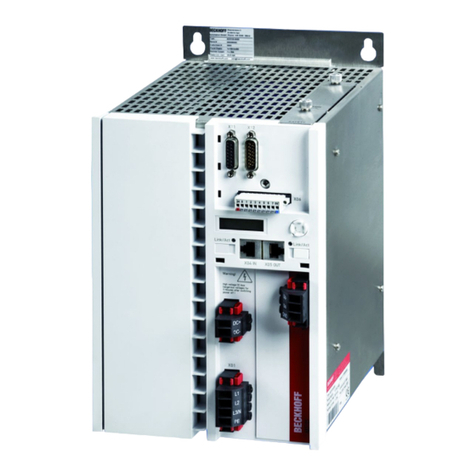
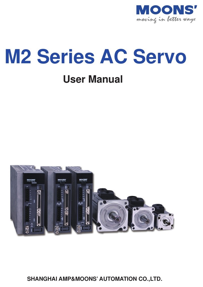
Smitec COSMOS 301 Series User manual

Servodrives / inverters series COSMOS 301X Installation, use and maintenance manual - EN
Smitec S.p. ., viale Vittorio Veneto 4, 24016 San Pellegrino Terme (BG), Italy, www.smitec.it
Installation, use and maintenance manual
BEFORE STARTING UP THE COSMOS 3 1X SERVO-DRIVES, CAREFULLY
READ THIS MANUAL AND FOLLOW ALL INSTRUCTIONS, IN ORDER TO
ENSURE MAXIMUM SAFETY
SERVO DRIVES
COSMOS 3 1X SERIES
The technical data and the drawings in this manual might have been modified later;
always refer to the latest version.
Ver. 1.09 SMIT Cdd 1/74

Servodrives / inverters series COSMOS 301X Installation, use and maintenance manual - EN
CONTENTS
1 PR FAC .............................................................................................................................................................4
2 G N RAL INSTRUCTIONS .................................................................................................................................5
3 Safety instructions .................................................................................................................................................7
3.1 General information .......................................................................................................................................7
3.2 Precautions against risk of lectric Shock .....................................................................................................8
3.3 Precautions against hot components ............................................................................................................9
4 T CHNICAL F ATUR S ....................................................................................................................................10
4.1 Description ...................................................................................................................................................10
4.2 Technical specifications ...............................................................................................................................12
4.2.1 nvironmental features ........................................................................................................................12
4.2.2 Ratings .................................................................................................................................................13
4.2.3 Motor output .........................................................................................................................................13
4.2.4 Dynamic brake output ..........................................................................................................................14
4.2.5 ncoder input .......................................................................................................................................14
4.2.6 Resolver input ......................................................................................................................................14
4.2.7 Digital inputs ........................................................................................................................................14
4.2.8 Digital outputs ......................................................................................................................................14
4.2.9 Static brake output ...............................................................................................................................14
4.2.10 Counter input .....................................................................................................................................14
4.2.11 0 ÷ 10 V input .....................................................................................................................................14
4.2.12 4 ÷ 20 mA input ..................................................................................................................................15
4.2.13 Motor temperature sensor input .........................................................................................................15
4.2.14 0 ÷ 10 V output ...................................................................................................................................15
4.2.15 Reference voltage output ...................................................................................................................15
4.2.16 Thermocouple input ...........................................................................................................................15
4.3 Configurations / order codes .......................................................................................................................16
4.4 Model code ..................................................................................................................................................18
4.5 Accessories .................................................................................................................................................19
4.6 Heat dissipation ...........................................................................................................................................20
4.7 lectromagnetic compatibility ( MC) ...........................................................................................................22
4.8 Mechanical specifications ............................................................................................................................23
4.8.1 Weight .................................................................................................................................................. 23
4.8.2 xternal dimensions without operator interface ...................................................................................23
4.8.3 xternal dimensions with operator interface VISIO 3000 ....................................................................24
5 INSTALLATION AND START-UP .......................................................................................................................25
5.1 Preliminary operations .................................................................................................................................25
5.2 Positioning and installation ..........................................................................................................................25
5.3 lectrical connections ..................................................................................................................................27
5.3.1 Connections (KZ010374) .....................................................................................................................27
5.3.2 Connections (KZ010375 and KZ010376) ............................................................................................28
5.3.3 Connections (KZ010377 and KZ010389) ............................................................................................29
5.3.4 Connections (KZ010385) .....................................................................................................................30
5.3.5 Connections (KZ010387 and KZ010388) ............................................................................................31
5.4 Mains power and MI filters ........................................................................................................................32
5.4.1 Power supply with IT distribution networks ..........................................................................................33
5.4.2 Cables and protection devices .............................................................................................................34
5.5 Installation criteria for UL certification ..........................................................................................................36
5.6 Motor, brake resistor and DC bus wiring .....................................................................................................37
5.7 24V auxiliary and I/O power ........................................................................................................................41
5.7.1 Connections (KZ010374) .....................................................................................................................41
5.7.2 Connections (KZ010375 and KZ010376) ............................................................................................42
5.7.3 Connections (KZ010377 and KZ010389) ............................................................................................43
5.7.4 Connections (KZ010385) .....................................................................................................................44
5.7.5 Connections (KZ010387 and KZ010388) ............................................................................................45
5.7.6 24V auxiliary power ..............................................................................................................................46
5.7.7 24V digital inputs ..................................................................................................................................47
5.7.8 Counter input .......................................................................................................................................48
5.7.9 24V digital outputs ...............................................................................................................................49
5.7.10 Motor brake output .............................................................................................................................49
5.7.11 Incremental encoder ..........................................................................................................................50
5.7.12 Resolver .............................................................................................................................................52
5.7.13 Motor temperature sensor ..................................................................................................................54
5.7.14 0 to 10V analogue input and 10V reference generator ......................................................................55
5.7.15 4 to 20mA analogue input ..................................................................................................................56
Ver. 1.09 SMIT Cdd 2/74

Servodrives / inverters series COSMOS 301X Installation, use and maintenance manual - EN
5.7.16 0 to 10V analogue output ...................................................................................................................57
5.7.17 Thermocouple J input ........................................................................................................................58
5.8 Field bus ......................................................................................................................................................59
5.8.1 FL XTRON versions ...........................................................................................................................59
5.8.2 FLxIO versions .....................................................................................................................................60
5.9 RS485 interface ...........................................................................................................................................62
5.10 Removable operator interface (HMI) .........................................................................................................63
5.10.1 Function of the keys ...........................................................................................................................64
6 UPDATING TH FIRMWAR .............................................................................................................................65
7 STORAG ........................................................................................................................................................... 72
8 MAINT NANC .................................................................................................................................................. 73
9 DISPOSAL AND D MOLITION ..........................................................................................................................74
Ver. 1.09 SMIT Cdd 3/74

Servodrives / inverters series COSMOS 301X Installation, use and maintenance manual - EN
1 PREFACE
This manual provides the information required for installation, use and maintenance of servo-drives/inverters
of COSMOS 301X series.
The instructions included in this manual are addressed to the following professionals:
User User is a person, a company or an institution that buys the equipment and uses it for the
purposes it was designed for.
User / operator User or operator is a person authorized by the user to work on the equipment.
Qualified personnel It refers to all persons with specific competence, able to recognize and avoid the dangers
deriving from the use of the equipment.
The present instructions must be made available to all above persons.
Ver. 1.09 SMIT Cdd 4/74

Servodrives / inverters series COSMOS 301X Installation, use and maintenance manual - EN
2 GENERAL INSTRUCTIONS
The assembly instructions are an integral part of the equipment and must be kept for future reference, until it
is dismantled. The present instructions reflect the state of the art at the moment when the equipment was
sold; they will remain fully acceptable despite subsequent upgrades based on new experience.
DO NOT USE THE EQUIPMENT, NOR MAKE ANY INTERVENTION BEFORE INTEGRALLY
READING AND UNDERSTANDING THIS MANUAL.
IN PARTICULAR, ADOPT ALL SAFETY PRECAUTIONS AND PRESCRIPTIONS INDICATED IN THIS MANUAL.
THE EQUIPMENT CAN NOT BE USED FOR DIFFERENT PURPOSES THAN THE ONES DESCRIBED IN THIS
MANUAL; SMITEC S.p.A. SHALL NOT BE HELD RESPONSIBLE FOR ANY DAMAGES, INCONVENIENCES OR
ACCIDENTS DUE TO THE NON-COMPLIANCE WITH THE PRESCRIPTIONS.
In order to make the manual consultation easier, the following symbols have been adopted:
The indication of "FORBIDD N B HAVIOR".
The symbol "DANG R" is used when the non-compliance with the prescriptions or misuse
may cause serious injuries.
The symbol "DANG R OF HOT SURFAC S" is used when the non-compliance with the
prescriptions may cause serious injuries.
The symbol "DANG R OF L CTRICAL SHOCK" is used when the non-compliance with
the prescriptions may cause serious injuries.
The symbol "US OF INDIVIDUAL PROT CTIONS" means that protective gloves must be
worn.
The symbol "US OF INDIVIDUAL PROT CTIONS" means that protective glasses must
be worn.
The indication of "PARTICULAR R L VANT INFORMATION".
Ver. 1.09 SMIT Cdd 5/74

Servodrives / inverters series COSMOS 301X Installation, use and maintenance manual - EN
The safety prescriptions aim at establishing a series of behaviours and obligations to be complied with, while
performing the activities described later on in this manual.
These prescriptions constitute the prescribed method of operating the machine, in a way that is safe for
personnel, tools/equipment and environment.
Ver. 1.09 SMIT Cdd 6/74

Servodrives / inverters series COSMOS 301X Installation, use and maintenance manual - EN
3 Safety instructions
3.1 General information
Do not install or use the equipment before integrally reading and understanding this
manual. In case of difficulties of interpretation, contact SMIT C technical service.
It is absolutely forbidden to use the equipment for different purposes than the ones
described in this manual. The technical data and the drawings in this manual might have
been modified later; always refer to the latest version. All upgrades can be requested to
SMIT C S.p.A. directly.
Make sure that the personnel is qualified and adequately informed about the risks he may
run and how to avoid them.
The COSMOS 301X series servo drives is authorized can be used only after the
classification of the machine operating area and after checking the safety levels, which
must correspond to the assembly safety levels.
Precautions during handling and assembly
Use adequate tools during the assembly, in order to avoid crushing or abrasions.
Metal components and sharp surfaces may cause cuts and tears. In case of contact, be
very careful and wear the personal protection equipment.
Ver. 1.09 SMIT Cdd 7/74

Servodrives / inverters series COSMOS 301X Installation, use and maintenance manual - EN
3.2 Precautions against risk of Electric Shock
The high voltage of some accessories and components in the servo-driver/inverter might
cause electrocution, if the user came into contact with them. Be careful to the terminal
boards and to the motor/dynamic brake connection.
There are some condensers inside the driver which maintain a dangerous voltage for at
least 6 minutes after switching them off. Before starting any operation, make sure that the
driver has been switched off at least 6 minutes earlier and that the motor is still.
Avoid any metal components (screws, electrical cables…) fall into the driver during the
installation, because they might cause short-circuits.
The driver is an electric generator. The running speed becomes electric potential. High
voltage is already generated at 300 rpm.
During installation and maintenance, disconnect the device from the mains power supply.
Risk of lectric Shock.
Some components (such as the aluminium heat sink) are made of conductive materials.
They must be safely connected to the protective conductor (P /Ground) by using the
specific terminal strips, in order to avoid lectric Shock.
Never use the device if it is partially or totally disassembled. Risk of lectric Shock and/or
damages to people and properties.
Ver. 1.09 SMIT Cdd 8/74

Servodrives / inverters series COSMOS 301X Installation, use and maintenance manual - EN
3.3 Precautions against hot components
W RNING
The parts of the apparatus can reach an extremely high temperature in operating mode or
post-operation; take particular care not to touch the parts of the equipment in these cases,
or use special protections and precautions during handling: HOT SURFAC , RISK OF
BURN.
VERTISSEMENT
Les pièces de l'appareil peuvent atteindre une température extrêmement élevée en mode
de fonctionnement ou post-opération; veillez particulièrement à ne pas toucher les pièces
de l'équipement dans ces cas, ou utilisez des protections et des précautions spéciales
lors de la manipulation: SURFAC CHAUD , RISQU D BRÛLUR .
Ver. 1.09 SMIT Cdd 9/74

Servodrives / inverters series COSMOS 301X Installation, use and maintenance manual - EN
4 TECHNICAL FEATURES
4.1 Description
The servo-drives/inverters of the COSMOS 301X series have been designed for three-phase asynchronous
electrical motors and for brushless AC motors (BLAC). The core of the power section is an intelligent IGBT
module (IPM), featuring the necessary protections that guarantee an extreme reliability and efficiency,
besides reducing the need for external components. The servo-drives/inverters of the COSMOS 301X series
for asynchronous and brushless motors is constituted by an aluminium dissipater and by electronic boards
included in a special “plastic case”.
In particular, the servo-drives/inverters of the COSMOS 301X series for asynchronous and/or brushless AC
motors can control start/stop functions, motor speed and position and motor torque and can perform
diagnostic activity, etc. They are also used to manage abnormal conditions, by providing real-time diagnostic
information (diagnostics are included in the machine into which the drive is incorporated) that can be viewed
by connecting the system to other instruments (such as an HMI) or by using a “master” device (on versions
equipped with a field bus).
Servo-drives/inverters for asynchronous and brushless motors are mainly intended for the so-called “second
environment”, i.e. heavy industry. Some versions only require 230V AC single-phase power supply; others
require 24V DC auxiliary power.
The control logic is implemented by 32-bit micro-controllers, equipped with a set of instructions optimized for
speed and specialized in controlling precision motors. Thanks to their design features, the drives/inverters
can be considered as of digital type, because they are completely controlled by the micro-controller. As a
consequence, the servo-drive/inverter is a very flexible appliance which can be reset through a software and
is open to all improvements offered by the new technologies in the future.
The equipment is designed for asynchronous motors and brushless AC motors. It operates on 230VAC
single-phase power and on 24VDC auxiliary power (on certain versions only). Auxiliary power, when
applicable, is used to feed the control section of the device.
Versions equipped with field bus interface feature a “master” device sending commands to the equipment
(such as start, stop, motor speed/position, parameters for the motor and/or servo-drive/inverter, etc.),
besides having a diagnostic function.
Some versions of servo-drive/inverter can be connected to an external HMI display (model “VISIO 3000”),
which performs diagnostic functions, parametrization, parameters readout, analogue/digital values readout,
besides sending some commands to the equipment.
The equipment operation is controlled by micro-controllers, which can be updated by uploading new firmware
versions. They communicate through field bus, they can control analogue/digital I/O and the motor.
Ver. 1.09 SMIT Cdd 10/74

Servodrives / inverters series COSMOS 301X Installation, use and maintenance manual - EN
The servo-drives/inverters of the COSMOS 301X series comply with N 61800-3 (2004) + A1 (2012)
standards ( MC Requirements); they can be installed in the second environment (“Second Environment”,
category C3), provided they comply with the conditions indicated in this Installation, Use and Maintenance
Manual.
No ordinary/extraordinary maintenance is allowed for COSMOS 301X servo-drives/inverters; in case of bad
operation and/or break, it is necessary to replace the equipment integrally. Any repairs must be performed
exclusively by SMIT C S.p.A.
Ver. 1.09 SMIT Cdd 11/74

Servodrives / inverters series COSMOS 301X Installation, use and maintenance manual - EN
4.2 Technical specifications
4.2.1 Environmental features
Operational temperature 0 ÷ +40°C when operating at full load
0 ÷ +55°C with current derating
Pollution degree (UL) Use in Pollution degree 2 nvironment
Maximum surrounding air temperature
(UL) 0 ÷ +40 °C
Output current derating depending on
the ambient temperature
Output current derating depending on
the distance from obstructions
Air humidity during operation 5 ÷ 85% non condensing
Storage temperature -25 ÷ +55°C
Air humidity during storage 5 ÷ 95%
Transportation temperature -25 ÷ +70°C
Air humidity during transportation 5 ÷ 95%
Maximum altitude 1000 m above sea level at rated output current
2000 m above sea level with current derating
Output current derating depending on
the altitude
Ver. 1.09 SMIT Cdd 12/74
1000 4000
2000 3000 h [m]
Iout [%]
100
90
80
70
40 55
45 50 Tamb [°C]
Iout [%]
100
90
80
70
80 60 40 c [mm]
Iout [%]
100
90
80
70
100 20
c
c

Servodrives / inverters series COSMOS 301X Installation, use and maintenance manual - EN
4.2.2 Ratings
Mains voltage single-phase 230 VAC ± 15% 50/60 Hz
Distribution systems allowed TT, TN (operation with IT systems is possible only by disconnecting the
integrated mains filter)
Maximum short-circuit current 5 kA at the installation point
Maximum mains input current 10 A RMS
Auxiliary mains voltage 24 VDC -15 ÷ +20%; max ripple 5% of the rated value
Maximum auxiliary current
Depending on the various models:
KZ010374, KZ010375, KZ010376: 0.2 A
KZ010377, KZ010389: 2.0 A
KZ010387, KZ010388: 0.5 A
KZ010385: 0.4 A
4.2.3 Motor output
Output voltage Three-phase 0 ÷ 230 V
Output frequency
Depending on the various models:
KZ010374, KZ010375, KZ010377, KZ010387, KZ010388, KZ010389:
0÷500 Hz
KZ010376, KZ010385: 0÷128 Hz
Switching frequency
Depending on the various models:
KZ010374, KZ010375, KZ010376: 4/8/10/12/16 kHz
KZ010377, KZ010385, KZ010387, KZ010388, KZ010389: 5/10/15 kHz
Maximum output current
4.2 A DC
4.2 A RMS with fsw = 4 kHz
Output current derating depending on the switching frequency,
according to the following diagram:
Asynchronous motor maximum size 0.75 kW (shaft rating)
Available active power 1 kW max. (1.34 HP)
Peak output current 15 A
Protections Against phase-to-phase short-circuit, overload, servo-drive overheating,
motor overheating
Ver. 1.09 SMIT Cdd 13/74
4 5 6 7 8 9 10 11 12 13 14 15 16
0
1
2
3
4
5
fPWM [kHz]
Iout [ARMS]

Servodrives / inverters series COSMOS 301X Installation, use and maintenance manual - EN
4.2.4 Dynamic brake output
Type Control circuit of the brake resistor with IGBT
Protections Against brake resistor short-circuit
Brake resistor resistance 30 ÷ 150 Ω
Average available power 150 W max.
4.2.5 Encoder input
Type Input for readout of incremental encoder with 5 V differential signals
Maximum input frequency 200 kHz
Power supply 5 V, max 200 mA
4.2.6 Resolver input
Type Input for resolver readout
Excitation signal frequency 5 kHz
4.2.7 Digital inputs
Type (KZ 1 375 and KZ 1 376) 24 V digital inputs, compatible with type 1 and type 3, according to
I C 61131-2
Type (other versions) 24 V digital inputs
Max. frequency of input signal 1 kHz
4.2.8 Digital outputs
Type 24 V pnp (current-sourcing) digital outputs
Maximum available current 30 mA
Protections Against short-circuit, overload and overheating
4.2.9 Static brake output
Type (KZ 1 377 and KZ 1 389) 24 V pnp (current-sourcing) digital output
Type (KZ 1 387 and KZ 1 388) 24 V npn (current-sinking) digital output
Max. available current 500 mA
4.2.1 Counter input
Type 24 V digital input
Maximum input current 4.5 mA @ Vin=24 V
Input signal frequency range 0 ÷ 100 kHz
4.2.11 ÷ 1 V input
Input voltage range 0 ÷ 10 V DC
Input resistance 147 kΩ typ.
Resolution 12 bit
Ver. 1.09 SMIT Cdd 14/74

Servodrives / inverters series COSMOS 301X Installation, use and maintenance manual - EN
4.2.12 4 ÷ 2 mA input
Input current range 4 ÷ 20 mA DC
Resolution 12 bit
4.2.13 Motor temperature sensor input
Sensor type NTC, PTC and thermal trip device
Resolution 12 bit
4.2.14 ÷ 1 V output
Output voltage range 0 ÷ 10 V DC
Resolution 10 bit
Max. available current 10 mA
4.2.15 Reference voltage output
Output voltage 10 V DC - fixed value
Max. available current 10 mA
4.2.16 Thermocouple input
Sensor type Insulated thermocouples – J type
Input voltage range -6.3 ÷ +27.5 mV
Input temperature range
The diagram shows the temperature range depending on the cold joint
temperature:
Resolution 12 bit
Cold junction compensation internal
Sensor interruption detection yes (by internal pull-up and full-scale voltage readout)
Ver. 1.09 SMIT Cdd 15/74
-147
Tcold joint [°C]
T [°C]
-62
+502
+587
80
0

Servodrives / inverters series COSMOS 301X Installation, use and maintenance manual - EN
4.3 Configurations / order codes
Up to date, we defined some standard configurations of servo-drives/inverters, with their order code and type
number (4 figures, indicating the series, the maximum current and the release). These data are indicated on
the driver label.
Ver. 1.09 SMIT Cdd 16/74
TYPE * ** * - * *
Series
3 = 3000
Peak current
01 = 14Apk – 0,75kW
02 = 2 x 12Apk – 0,37kW
15 = 15Apk – 2.2kW
25 = 25Apk – 5.5kW
50 = 50Apk – 7.5kW
HW Version
Se uential number, depending on the other figures
Communication
C = EtherCAT
D = Sercos II
E = Ethernet
F = FlxIO
N = None
R = RS485
S = Sercos III
T = Flextron
Type of motor controlled
A = Asyncronous
B = Brushless
U = Brushless + Asyncronous

Servodrives / inverters series COSMOS 301X Installation, use and maintenance manual - EN
Order
code Type Field
bus Motor type Encoder type I/O Static
brake
Dynamic
brake
KZ010374 3010TA Flextron
Three-phase,
asynchronous
motor
- - - -
KZ010375 3010FU FLxIO
Brushless motors
+ Three-phase,
asynchronous
motors
Incremental encoder with
differential line-driver
outputs – 5V ch. ABUVW
2 x InD - X
KZ010376 3010FA FLxIO
Three-phase,
asynchronous
motors
Incremental encoder with
differential line-driver
outputs – 5V ch. AB
2 x InD - -
KZ010377 3010RU RS485
Brushless motors
+ Three-phase,
asynchronous
motors
Incremental encoder with
differential line-driver
outputs – 5V ch. ABUVW
+ resolver
17 x InD
5 x OutD
2 x InA
1 x OutA
X X
KZ010385 3012RA RS485
Three-phase,
asynchronous
motors
-
4 x InD
6 x OutD
1 x InTC
- -
KZ010387 3011RU RS485
Brushless motors
+ Three-phase,
asynchronous
motors
Incremental encoder with
differential line-driver
outputs – 5V ch. ABUVW
+ resolver
4 x InD
1 x OutD
2 x InA
1 x OutA
X X
KZ010388 3011RA RS485
Three-phase,
asynchronous
motors
Incremental encoder with
differential line-driver
outputs – 5V ch. AB
4 x InD
1 x OutD
2 x InA
1 x OutA
X -
KZ010389 3010RA RS485
Three-phase,
asynchronous
motors
Incremental encoder with
differential line-driver
outputs – 5V ch. AB
17 x InD
5 x OutD
2 x InA
1 x OutA
X -
Ver. 1.09 SMIT Cdd 17/74

Servodrives / inverters series COSMOS 301X Installation, use and maintenance manual - EN
4.4 Model code
The specific features of a servo-driver/inverter of the COSMOS 301X series are defined by an alpha-numeric
code printed on the device label, near the MOD L code. Here is the code table:
Ver. 1.09 SMIT Cdd 18/74
MODEL * * * * * . * * * * * . * * * * *
Reserved
Reserved
Auxiliary power
1 = 24Vdc
Main power
1 = 230Vac 1PH
Maximum output current - Asynchronous motor power
1 = 15Apk – 0,75kW
2 = 2 x 12Apk – 0,370kW
Dynamic brake
0 = Absent
1 = Present
Encoder inputs and thermocouple
0 = Absent
1 = Incremental 5V diff. AB
2 = Incremental 5V diff. AB+UVW
3 = Resolver
4 = Resolver + Incremental 5V diff. AB
5 = Resolver + Incremental 5V diff. AB+UVW
6 = TC + Incremental 5V diff. AB
7 = TC + Incremental 5V diff. AB+UVW
8 = TC
Motor brake
0 = Absent
1 = Present
Physical layer communication/fieldbus
0 = Absent
1 = EIA-RS485, 2 ports, max 2.5Mbps, automatic termination
2 = EIA-RS485, 1 porta, max 2.5Mbps, no termination
3 = EIA-RS485, 1 porta, max 250kbps, no termination
4 = EIA-RS485, 1 porta, max 2.5Mbps, termination inserted
Support VISION 3000
0 = Absent
1 = Present
Pulse counter digital input
0 = Absent
1 = Present
Common digital inputs
0÷9 = 0÷9
inputs
i
A÷G = 10÷16
inputs
Common digital outputs
0÷6 = 0÷6 outputs
Analog input
0 = Absent
1 = 0÷10V
2 = 4÷20mA
3 = 0÷10V/POT
4 = 0÷10V/POT + 4÷20mA
Analog output
0 = Absent
1 = 0÷10V

Servodrives / inverters series COSMOS 301X Installation, use and maintenance manual - EN
4.5 Accessories
The servo-drives/inverters of the COSMOS 301X series are supplied with a series of removable connectors
for power connection and I/O (where relevant). These connectors can be ordered separately, as well as
other accessories not included in the drive.
Here is a list of the order codes.
Item Order code
Operator interface VISIO 3000 KZ010262
Connector 24VDC for code KZ010374 KF101066
Connector 24VDC for code KZ010375/76 KF101067
Connector 24VDC and I/O (8x2) for code KZ010377/89 KF101064
Connector I/O (9x2) for code KZ010377/89 KF101065
Connector 24VDC and I/O (8x1) for code KZ010385/87/88 KF101068
Connector I/O (9x1) for code KZ010385/87/88 KF101069
Adapter cable RS485 for programming KF131284
Converter USB-RS485 KZ020087
Software WinMicro for programming KW050111
Ver. 1.09 SMIT Cdd 19/74

Servodrives / inverters series COSMOS 301X Installation, use and maintenance manual - EN
4.6 Heat dissipation
During operation, a servo-drive/inverter dissipates a certain quantity of electric power, due to the imperfect
nature of electronic components. As a consequence, the components temperature increases, especially for
the power section components. This increase must be taken into consideration in order to correctly
determine the capacity of the electrical panel cooling system.
The amount of dissipated power depends on the supplied output current and on the switching frequency of
the PWM signals. The below diagram, valid for all releases, shows the total thermal dissipation, depending
on the rated output current; the four curves represent different switching frequencies. Please consider that:
•In case of variable output current, the average dissipated power must not be calculated from the
average current only, but also by including instantaneous power dissipation.
•Power dissipation mostly depends on the drive switching frequency.
•The dissipated power from the braking resistors must be calculated separately.
•Power dissipation scarcely depends on the power factor of the load, but mostly on the absolute value of
the output current; this is to say that the dissipated power is not strictly linked to the active power
supplied to the load.
Ver. 1.09 SMIT Cdd 20/74
This manual suits for next models
16
Table of contents
Other Smitec Servo Drive manuals
Popular Servo Drive manuals by other brands
Allen-Bradley
Allen-Bradley MP-Series installation instructions
SYNAPTICON
SYNAPTICON SOMANET Node 400 Documentation
YASKAWA
YASKAWA SGD7W Series Selection Manual
SSD Drives
SSD Drives 637 product manual
YASKAWA
YASKAWA Sigma-7-S Series product manual
AXOR Industries
AXOR Industries MiniMagnum Series Service manual
Mitsubishi Electric
Mitsubishi Electric MR-J4W2-0303B6 instruction manual
HPI Racing
HPI Racing SF-20W instruction manual
Moons'
Moons' Applied Motion Products SSDC-ECX-H Hardware manual
Mitsubishi Electric
Mitsubishi Electric Melservo-J3 Series MR-J3-B manual

Omron
Omron 1S Series instruction manual

Panasonic
Panasonic MINAS A6N Series manual
