CopperOptics PairGain PG-Flex FRE-765 List 5 User manual

PAIRGAIN TECHNOLOGIES Section 363-765-100
Technical Practice Revision 01
Engineering - PLANT Series February 12, 1996
Page 1
PAIRGAIN TECHNOLOGIES
PG-FLEX™REMOTE TERMINAL ENCLOSURE
MODEL FRE-765, List 1
PairGain #150-1365-01
CLEI Code: VAMRBB0ARA
CONTENTS PAGE
A PRODUCT OVERVIEW
1 DESCRIPTION AND
FEATURES 2
2. SPECIFICATIONS 2
3. CERTIFICATION 2
4. WARRANTY 2
B. FUNCTIONAL DESCRIPTION
5. OPERATIONAL
CAPABILITIES 3
6. BACKPLANE
CONNECTIONS 3
C. INSTALLATION AND TEST
7. UNPACKING 7
8. INSTALLATION
REQUIREMENTS 7
9. MOUNTING 7
10. WIRING 7
11. TURN-UP AND TESTING 7
12. TROUBLESHOOTING 7
CAUTION
This product incorporates static sensitive components.
Proper electrostatic discharge procedures must be
followed.
Figure 1. FRE-765 RT Enclosure, List 1. The PairGain FRE-
765 houses the RT Line and Channel Units and connections for
subscriber circuits.

Section 363-765-100
Revision 01
Page 2
A. PRODUCT OVERVIEW
1. DESCRIPTION AND FEATURES
1.01 The PG-Flex FRE-765 Remote Terminal (RT)
Enclosure (Figure 1) provides convenient
mounting of RT Line and Channel Units as well as
termination points for subscriber circuits, power, and
metallic test access. The Enclosure supports up to 32
channels with one RT Line Card and up to four RT
Channel Cards. Amp Quiet Front™ terminations are
provided on the backplane for HDSL and Bypass
connections. The enclosure may be pole- or wall-
mounted and is environmentally sealed for outside plant
installations.
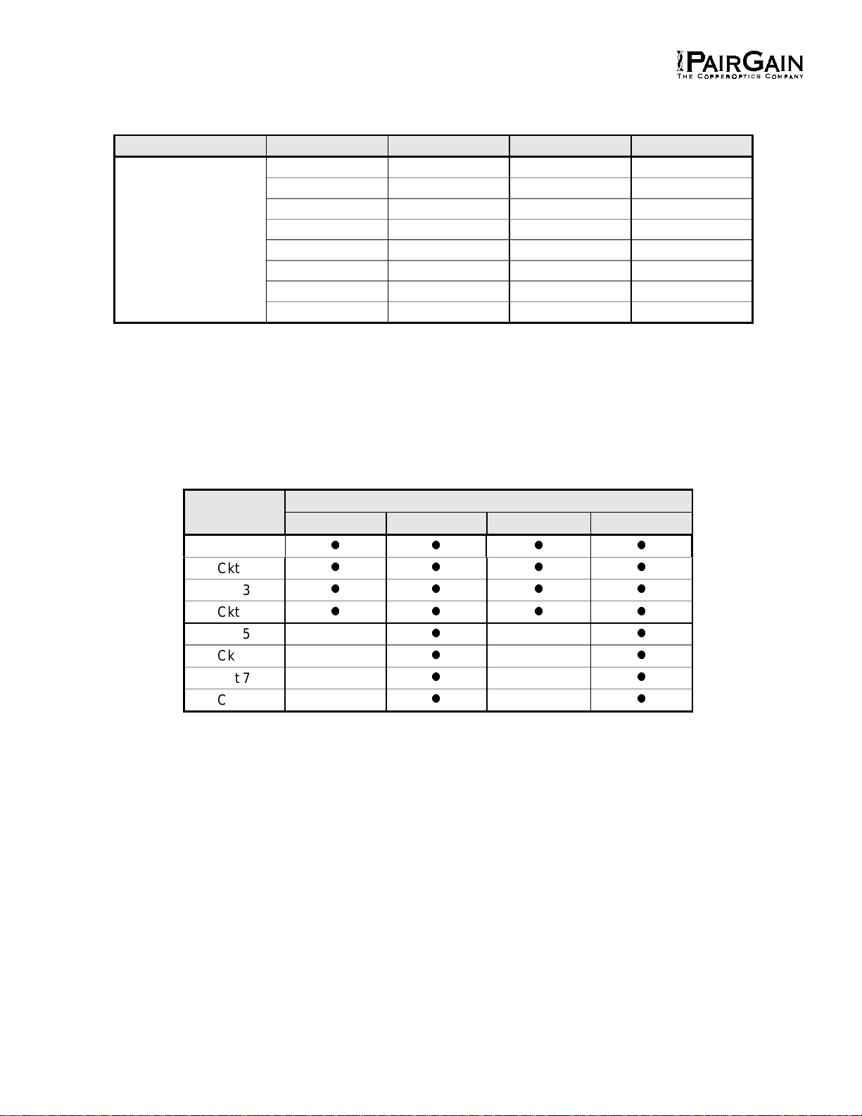
1.02 The RT Enclosure accommodates the following
PairGain units:
• One Line Unit
• Four Channel Units
1.03 Revision History of this practice.
Revision 01
February 12, 1996
a) Initial release.
1.04 FRE-765 RT Enclosure, List 1, features:
• Pole or Wall Mounting
• Backplane Amp Quiet Front™Connections
for HDSL Inputs, Metallic Bypass
• Line Powered from Central Office Terminal
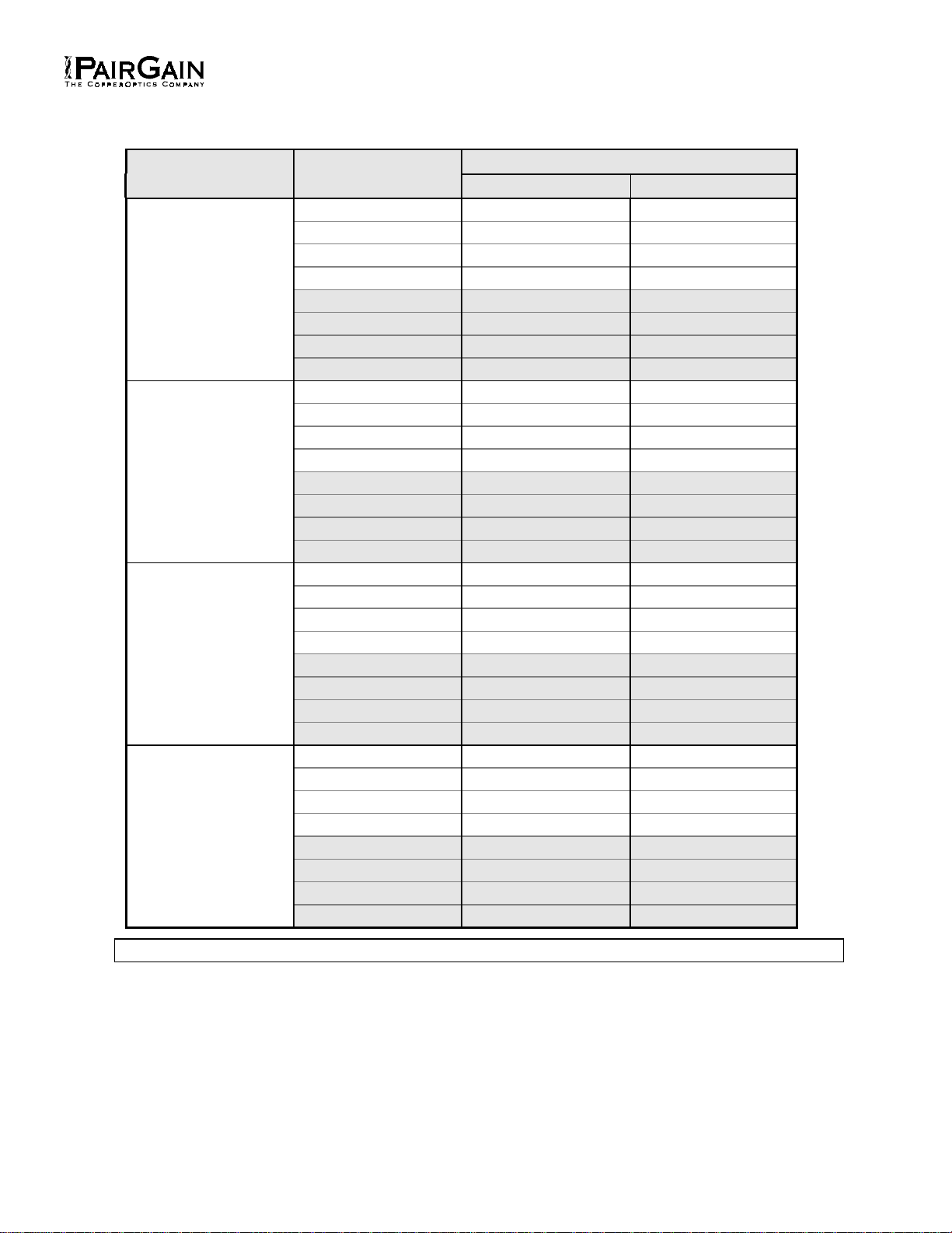
2. SPECIFICATIONS
Operating Temperature & Humidity
-40° to + 65° Celsius, 5% to 95%
(non condensing)
Operating Elevation
200 feet (60 m) below sea level to
13,000 (4,000 m) feet above sea level.
Dimensions
Height: 19.25” (48.3 cm)
Width: 11.75” (29.2 cm)
Depth: 5.40” (13.3 cm)
Weight
19.4 lb. (8.8 kg)
3. CERTIFICATION
3.01 FCC Compliance. The FRE-765 RT Enclosure
complies with the limits for Class A digital
devices pursuant to Part 15 of the FCC rules. These
limits are designed to provide reasonable protection
against harmful interference when the equipment is
operated in a commercial environment. This equipment
uses and can radiate radio frequency energy and, if not
installed and used in accordance with the instruction
manual, may cause harmful interference to radio
communications. Operation of this equipment in a
residential area is likely to cause harmful interference in
which case the user will be required to correct the
interference at his own expense.
3.02 Refer to the installation section of the
appropriate instruction manual for the unit you
are installing to get information on:
• Cabling
• Proper connections
• Grounding
• Line power
3.03 All wiring external to the product(s) should follow
the provisions of the current edition of the
National Electrical Code.
4. WARRANTY
4.01 PairGain Technologies warrants this product to
be free of defects and to be fully functional for a
period of 36 months from the date of original shipment,
given proper customer installation and regular
maintenance. PairGain will repair or replace any unit
without cost during this period if the unit is found to be
defective for any reason other than abuse or improper
use or installation.
4.02 This module should not be field repaired. If it
fails, replace it with another unit and return the
faulty unit to PairGain for repair. Any modifications of the
unit by anyone other than an authorized PairGain
representative will void the warranty.
4.03 If a unit needs repair, call PairGain for a Return
Material Authorization (RMA) number and return
the defective unit, freight prepaid, along with a brief
description of the problem, to:
PairGain Technologies, Inc.
14402 Franklin Avenue
Tustin, CA 92680
ATTN: Repair and Return Dept.
(800) 638-0031
4.04 PairGain will continue to repair faulty modules
beyond the warranty program at a nominal
charge. Contact your PairGain sales representative for
details and pricing.

Section 363-765-100
Revision 01
Page 3
B. FUNCTIONAL DESCRIPTION
5. OPERATIONAL CAPABILITIES
5.01 The RT Enclosure is installed in the field,
typically on a pole or wall. The Enclosure
accepts any of the following plug-in units:
• One Line Unit
• One to four Channel Units
5.02 Each Enclosure requires one Line Unit and from
1 to 4 Channel Units. The RT is powered over
the HDSL pairs connecting it to the FCS-718 Central
Office Terminal (COT) Shelf.
6. BACKPLANE CONNECTIONS
6.01 The backplane of the FRE-765 RT Enclosure
(Figure 2) contains the following connectors and
fuse: • Subscriber Lines (Tables 1 through 3)
• Test and Configuration (Table 4)
• HDSL (Table 5)
• Local Power (Table 6)
• Fuse (Table 7)
6.02 Tables 1 through 7 identify each connector and
fuse by type and describes the function of each
connector terminal.
Figure 2. Backplane of the FRE-765 RT.

Section 363-765-100
Revision 01
Page 4
TABLE 1 RT ENCLOSURE CIRCUIT ASSIGNMENTS
Line Unit Channel Unit 1 Channel Unit 2 Channel Unit 3 Channel Unit 4
Refer
Ckt 1 Ckt 1 Ckt 1 Ckt 1
to
Ckt 2 Ckt 2 Ckt 2 Ckt 2
Table x
Ckt 3 Ckt 3 Ckt 3 Ckt 3
for
Ckt 4 Ckt 4 Ckt 4 Ckt 4
Line
Ckt 5 Ckt 5 Ckt 5 Ckt 5
Unit
Ckt 6 Ckt 6 Ckt 6 Ckt 6
Termination
Ckt 7 Ckt 7 Ckt 7 Ckt 7
Ckt 8 Ckt 8 Ckt 8 Ckt 8
Notes: 1. Each PG-Flex channel unit provides four (4) or eight (8) circuits, depending on the service
offering (i.e. POTS, ISDN, DDS, etc.) of the channel unit – refer to Table 2.
2. For channel units providing four (4) circuits, circuits Ckt 1 through Ckt 4 are used for tip
and ring terminations. For channel units providing eight (8) circuits, circuits Ckt 1 through
Ckt 8 are used for tip and ring terminations.
3. For a 24-channel system, a maximum of 24 circuits may be provisioned.
TABLE 2 CHANNEL UNIT CIRCUIT UTILIZATION
Channel Channel Unit Service Configurations
Unit 4-Ch. POTS 8-Ch. POTS 4-Ch. ISDN 4-Ch. DDS
Ckt 1
llll
Ckt 2
llll
Ckt 3
llll
Ckt 4
llll
Ckt 5
ll
Ckt 6
ll
Ckt 7
ll
Ckt 8
ll

Section 363-765-100
Revision 01
Page 5
TABLE 3 RT ENCLOSURE CONNECTOR P1
Channel Connector P1
Unit Circuit Ring Tip
11331
2342
3353
4364
549 17
6 50 18
7 51 19
8 52 20
21375
2386
3397
4408
553 21
6 54 22
7 55 23
8 56 24
31419
24210
34311
44412
557 25
6 58 26
7 59 27
8 60 28
4 1 45 13
24614
34715
44816
561 29
6 62 30
7 63 31
8 64 32
Note:
Shaded terminations only used with the 8 Channel POTS or 4 Channel DDS Units.

Section 363-765-100
Revision 01
Page 6
TABLE 4. RT ENCLOSURE CONNECTORS (TEST & CONFIGURATION)
Connector Type Function
ID_0 GND 0.45 mm
Wire Wrap
(No Connection - Future)
ID_1 GND 0.45 mm
Wire Wrap
(No Connection - Future)
ID_2 GND 0.45 mm
Wire Wrap
(No Connection - Future)
TEST_IN_TIP
TEST_IN_RING 0.45 mm
Wire Wrap Test connection looking into the RT channel unit for the selected
subscriber. This connection must be set up through the PG-Flex
RS-232 maintenance port.
TEST_OUT_TIP
TEST_OUT_RIN
G
0.45 mm
Wire Wrap Test connection looking into the drop of the selected subscriber.
This connection must be set up through the PG-Flex RS-232
maintenance port.
BYPASS_T
BYPASS_R 0.45 mm
Wire Wrap Termination for the metallic bypass pair to the COT.
SSC1_A
SSC1_B 0.45 mm
Wire Wrap Special Signaling Channel #1. A user-definable input (through the
RS-232 Maintenance Port at the COT) that produces an alarm at
the COT based on a condition at the RT. This requires a contact
closure between SSC1_A and SSC1_B.
SSC2_A
SSC2_B 0.45 mm
Wire Wrap Special Signaling Channel #2. A user-definable input (through the
RS-232 Maintenance Port at the COT) that produces an alarm at
the COT based on a condition at the RT. This requires a contact
closure between SSC2_A and SSC2_B.
TABLE 5. RT ENCLOSURE CONNECTORS (HDSL)
Connector Type Function
HDSL_1_T
HDSL_1_R AMP
Quiet
Front™
Tip and ring terminations for HDSL Pair #1 of System #1 from the
COT. +130 V dc is simplexed on this line for powering the RT.
HDSL_2_T
HDSL_2_R AMP
Quiet
Front™
Tip and ring terminations for HDSL Pair #2 of System #1 from the
COT. -130 V dc is simplexed on this line for powering the RT.
PWR_1_T
PWR_2_R AMP
Quiet
Front™
(No Connection - Future)
PWR_2_T
PWR_2_R AMP
Quiet
Front™
(No Connection - Future)
TABLE 6. RT ENCLOSURE CONNECTORS (LOCAL POWER)
Connector Type Function
-48V Screw CO Battery (-48 V dc)
GND Screw CO Ground
CHASSIS GND Screw Chassis Ground
Note:
CO Ground is separate from Chassis Ground in PG-Flex. Technicians can
connect them on the RT Backplane by connecting the “CHASSIS GND” wire-wrap post to
the adjacent “GND” wire-wrap post.

Section 363-765-100
Revision 01
Page 7
TABLE 7. RT ENCLOSURE FUSE
Fuse Type Function
F1 GMT 2A Provides over-current protection between RT enclosure and local -48 V
dc battery. This fuse is not used when the RT is line powered from the
COT.
C. INSTALLATION AND TEST
7. UNPACKING
7.01 Upon receipt of the equipment, proceed as
follows: 1. Unpack each container and visually inspect it
for signs of damage. If the equipment has
been damaged in transit, immediately report
the extent of damage to the transportation
company and to PairGain. Order replacement
equipment if necessary.
2. Check the contents versus the packing list to
ensure complete and accurate shipment. If
the shipment is short or irregular, contact
PairGain as described in Section 4. If you
must store the equipment for a prolonged
period, store the equipment in its original
container.
8. INSTALLATION REQUIREMENTS
8.01 The following installation requirements apply:
1. Environmental Considerations. The RT is
designed to operate in an outside plant
environment. It can operate in a temperature
range of -40°C to +65°C and a humidity
range of 5% to 95% (non-condensing).
2. Mounting. The RT enclosure is equipped
with external mounting flanges with 3/8-inch
holes for pole or wall mounting. The
technician must provide the appropriate
mounting hardware.
3. Power. The RT derives its power from the
HDSL lines connected to the COT shelf in
the central office.
4. HDSL Lines. Two HDSL pairs are
terminated in the RT enclosure.
5. Subscriber Lines. One 32-pair, Amphenol
connector (male) is provided for extending
the subscriber lines from the RT to a
suitable termination block. If the RT is
mounted outside, then the subscriber lines
may require primary protection using gas
tube (or solid state) protectors.
6. Metallic Test Pair. One (optional) metallic
test pair for subscriber line testing is
terminated in the RT enclosure.
9. MOUNTING
9.01 The FRE-765 RT Enclosure may be mounted on
a pole or wall. Local practices should be
followed to ensure a secure mounting. The RT enclosure
should be mounted such that there is easy access to the
cable entry points on the bottom of the enclosure and
there is adequate room to open the door completely to
facilitate installation.
10. WIRING
10.01 All cabling into the RT Enclosure is through the
bottom entry points. Perform the wiring
procedures described in Table 8.
11. TURN-UP AND TESTING
11.01 Refer to the COT Line Unit Technical Practice or
RT Line Unit Technical Practice for complete
COT and RT turn-up and testing procedure.
12. TROUBLESHOOTING
12.01 Refer to the COT Line Unit Technical Practice or
RT Line Unit Technical Practice for complete
COT and RT troubleshooting procedures.

Section 363-765-100
Revision 01
Page 8
TABLE 8. RT WIRING PROCEDURES
Step Connection Action
1 Chassis
Ground
Note:
Use 6 AWG, or larger, wire to ensure a good ground connection to the
RT.
a. Route the chassis ground wire through the small cable clamp on the bottom
right side of the enclosure.
b. On the RT backplane, connect one end of the chassis ground wire to grounding
lug CHASSIS GND.
c. Connect the other end of the chassis ground wire to a suitable ground
termination point (ground rod or cold water pipe).
2 HDSL Lines a. Route the HDSL lines through the large cable clamp on the bottom left side of
the enclosure.
b. Terminate HDSL Pair #1 onto the Quiet-Front™ terminals HDSL_1_T (Tip) and
HDSL_1_R (Ring).
c. Terminate HDSL Pair #2 onto the Quiet-Front™ terminals HDSL_2_T (Tip) and
HDSL_1_R (Ring).
3 Bypass Pair a. Route the bypass pair through the large cable clamp on the bottom right side of
the enclosure.
b. Terminate the bypass pair on the Quiet Front™ terminals BYPASS_T and
BYPASS_R.
4 Subscriber
Lines a. The unterminated end of the subscriber line cable should be passed through the
large cable clamp on the right side of the enclosure from the inside of the
enclosure.
b. Connect the 16-pair Amphenol connector to P1 and secure with the connector
mounting screw and cable tie.
c. Attach the wires at the unterminated end of the subscriber cable onto a suitable
connector block or the protector module.
5 Verify
Connections
Note:
The following verifications should be done before any cards are inserted
in the COT shelf.
a. Visually ensure the ground wire is tightly secured to the grounding lug inside the
RT Enclosure and at the ground termination point.
b. Visually verify the HDSL lines are terminated properly and with the correct
orientation. If the HDSL lines are not connected properly, the COT will not
communicate with the RT.
c. Verify that the HDSL lines are “dry”:
1) There should be 0 V dc between the tip and ring, tip and ground, and ring
and ground of each of the HDSL pairs terminated at the RT.
2) There should be greater than 100 kohms resistance between tip and
ground, and ring and ground of each of the HDSL pairs terminated at the
RT.
Copyright © 1996, PairGain Technologies, Inc. PairGain is a registered trademark, CopperOptics and PG-Flex are
trademarks of PairGain Technologies, Inc. Quiet Front is a registered trademark of AMP Corporation.
Other manuals for PairGain PG-Flex FRE-765 List 5
2
This manual suits for next models
2
Table of contents
Other CopperOptics Enclosure manuals
Popular Enclosure manuals by other brands

Stahl
Stahl 8225 Series operating instructions

Stahl
Stahl 8250 Series operating instructions

Sensys Networks
Sensys Networks FlexRadio Cabinet quick start guide

Panduit
Panduit PanZone PN323 installation instructions

Corsair
Corsair Carbide series installation guide

Rocket Fish
Rocket Fish RF-HD3025 Guide de l'utilisateur