CopperOptics PairGain HiGain HRE-421 User manual

PAIRGAIN TECHNOLOGIES Section 100-421-100
Technical Practice Revision 05
Engineering - PLANT Series August 15, 1995
Page 1
QUICK INSTALLATION GUIDE FOR
PAIRGAIN™TECHNOLOGIES HIGAIN™REMOTE ENCLOSURE
MODEL HRE-421 Issue 1
List 1 PairGain # 150-1125-01, CLEI: T1MFFB04RA
List 2 PairGain # 150-1125-02, CLEI: T1MFFC04RA
CONTENTS PAGE
A. PRODUCT OVERVIEW
1. GENERAL 2
2. CERTIFICATION 2
3. WARRANTY 2
4. TECHNICAL ASSISTANCE 3
B. INSTALLATION
5. LIST OF MATERIAL 3
6. MOUNTING 3
7. WIRING 3
8 TURN UP 4
CAUTION
This product incorporates static sensitive components.
Proper electrostatic discharge procedures must be
followed.
Figure 1. Left and right view of HRE 421, List 1
Enclosure.

Section 100-421-100
Revision 05
Page 2
1. DESCRIPTION AND FEATURES
1.01 This Data Sheet describes installation of the
HiGain HRE-421 Mounting Enclosure for
HRU-412 Remote Units.
1.02 Revision—05, August 15, 1995
a) Corrected CLEI Code and Part no.
b) Revised document format.
1.03 This document is part of a set. Refer to the
Description and Application Technical
Practice #125-800-100 for additional information on
the HiGain System and to #150-412-100 for
information on the HRU-412 remote unit.
1.04 The PairGain HRE-421 shelf houses one
HRU-412, has a Lexan front cover, and is wall
or desk mountable. The unit consists of a wall mount
section and a cover which slides over and is attached
to the wall mount section. The wall mount section has
the 400-type connector that accepts the HRU 412. It
also contains a 14-position terminal block, TB1, for
access to all interface signal connections, an RJ-48C
List 1) or RJ48X (List 2) connector for connecting DS1
leads and a DB9 RS-232 jack (J2) for telco access to
the HIGAIN maintenance test system. A 2 position
terminal block TB2 ,for access to local 48 V power
and circuit ground, and a 48 V (1 amp) fuse are
provided for the HRU-412, List 7 which can be locally
powered. A rear panel punch-out labeled LEC (Local
Exchange Carrier) provides cable routing to these
inner connectors. The cover, which has the Lexan end
plate, slides over the wall mounted section and is
secured to it with a screw.
2. CERTIFICATION
2.01 UL Listing: The HRE-421 is a UL Listed
component. Use normal caution when
installing or modifying telephone lines. Dangerous
voltages may be present. It is also considered
imprudent to install telephone wiring during a lightning
storm. Always disconnect all telephone lines and
power connections from wall outlets before servicing
or disassembling this equipment.
2.02 Refer to the installation section of the
appropriate instruction manual for the unit you
are installing for:
• Cabling information
• Proper connections
• Grounding information
• Line vs. local power
All wiring external to the product(s) should follow the
provisions of the current edition of the National
Electrical Code.
2.03 CSA Certification: The HRE-421 has been
tested and found to comply with CSA
Standard C22.2 -950 with telecommunication
features.
3. WARRANTY
3.01 PairGain Technologies warrants this product
to be free of defects and to be fully functional
for a period of 36 months from the date of original
shipment, given proper installation and regular
maintenance. PairGain will repair or replace any unit
without cost during this period if the unit is found to be
defective for any reason other abuse or improper use
or installation.
3.02 This module should not be field repaired. If it
fails, replace it with another unit and return
the faulty unit to PairGain for repair. Any modifications
of the unit by anyone other than an authorized
PairGain representative will void the warranty.
3.03 If a unit needs repair, call PairGain for a
Return Material Authorization (RMA) number
and return the defective unit, freight prepaid, along
with a brief description of the problem, to:
PairGain Technologies, Inc.
14402 Franklin Avenue
Tustin, CA 92680
ATTN: Repair and Return Dept.
(714)-832-9922
(800) 638-0031
3.04 PairGain will continue to repair or replace
faulty modules beyond the warranty program
at a nominal charge. Contact your PairGain sales
representative for details and pricing.

Section 100-421-100
Revision 05
Page 3
4. TECHNICAL ASSISTANCE
4.01 PairGain Technical Assistance is available
24-hours-a-day, 7-days-a-week by contracting
PairGain’s Customer Service Engineering group at
one of the following numbers:
Telephone: (800) 638-0031
(714) 832-9922
Fax: (714) 832-9924
During normal business hours (8:00 AM to 5:00 PM,
Pacific Time, Monday - Friday, excluding holidays),
technical assistance calls are answered directly by a
Customer Service Engineer. At other times, a request
for technical assistance is handled by an on-duty
Customer Service Engineer through a callback
process. This process results in a callback within 30
minutes of initiating the request.
In addition, PairGain maintains a computer bulletin
board system for obtaining current information on
PairGain products, product troubleshooting tips and
aids, accessing helpful utilities, and for posting
requests or questions. This system is available 24-
hours-a-day by calling (714) 730-3299. Transmission
speeds up to 28.8 kbps are supported with a
character format of 8-N-1.
5. LIST OF MATERIAL
5.01 The following material is included with each
HRE-421:P
Description Qty.
HRE-421 Technical Data
Sheet 1
#10x3/8 pan hd. sht. metal
screw 3
10-32x3/8 button tamper
proof screw 1
Circuit Assignment Label 1
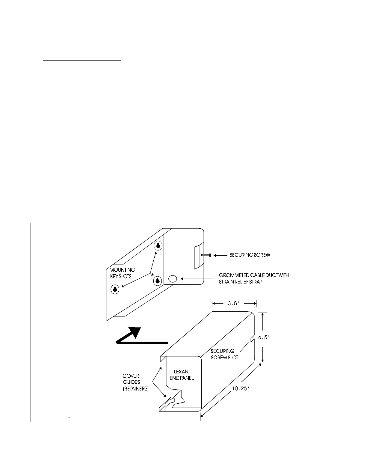
The tamper proof screw can replace the factory
provided blade “securing screw” shown in Fig 2. This
screw requires an Allen key wrench, available on
requrest, to install. It is intended to provide additional
security if desired. The gummed Circuit Assignment
Label is for circuit I.D. It can be attached to any
convenient location on the enclosure.
6. MOUNTING
6.01 See Figures 1 and 2. Select a location for
wall mounting the unit which will allow
sufficient access to wiring connections on the right
and indicators, test jacks, etc., on the left. Lift the
cover off the mounting plate and use it as a template
for drilling or locating mounting holes. Attach the plate
securely to the wall.
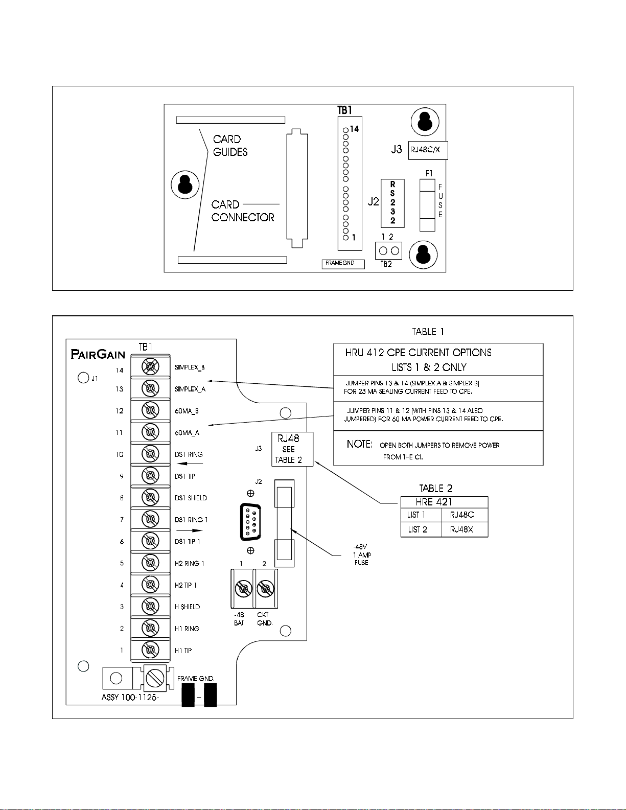
7. WIRING
7.01 Power and Grounding: See Figure 4.
Attach earth ground to FRAME GND if local
practice dictates. Terminals 3 & 8 of TB1 are
connected to pins 7 & 8 (S & S1) respectively of J3 in
Figures 5 & 6. They are used to terminate the shields
from the two CPE DS1 pairs and are provided for
DS1 shield continuity if desired. These terminals are
not connected to either Circuit or Frame Ground, but
may be wired to either if required. The -48 V battery
connection to TB2 is only required when using an
HRU-412 that is provisioned for local powering.
7.02 HDSL Connections: Refer to Figure 4.
Connect HDSL loop 1 T & R to pins 1 (H1
TIP) and 2 (H1 RING) respectively of TB1. Connect
HDSL loop 2 T & R to pins 4 (H2 TIP 1) and 5 (H2
RING 1) respectively of TB1. Since the HDSL signals
are bi-directional, they do not carry a”transmit” or
“receive” designation. With reference to T1
terminology, however, Loop 1 is called the “receive
pair” and Loop 2 the “transmit pair”. Note that if these
leads are reversed, a “CHREV” message is displayed
in the ALARMS display field when viewing the HRU
STATUS screen from a HIGAIN terminal interface
port. This condition does not affect system operation
but it should be corrected to avoid any confusion
regarding the identities of the 2 HDSL loops. Note that
this CHREV message does not appear on the HLU’s
status screen.
7.03 DS1 Connections to CI: The DS1 CPE
interface ports may be connected to either the
RJ-48C (Fig.5)/RJ-48X (Fig.6) jack (J3), located on
the rear panel of the HRE-421, or directly to TB1. If
TB1 is used, connect the DS1 output from the CPE to
terminals 9 and 10. Connect the DS1 input to the CPE
to terminals 6 and 7. Note if TB1 is used for the CPE
access when using the List 2 HRE-421, the shorted
pins in the RJ-48X jack J3 must be opened. This is
accomplished by inserting a dummy RJ-48 plug into
J3.

Section 100-421-100
Revision 05
Page 4
7.04 Current feed jumpers: See Figure 4.
List 1 & 2 HRU Connections: When the List 1
or 2 HRU-412 is being inserted into the HRE-
421, jumper TB1 terminals 11 through 14 as required
by the service order to provide none, 23 mA or 60 mA
current feed toward CPE over the DS1 leads.
List 3 ,4, 6 and 7 HRU Connections: When
the List 3, 4, 6 or 7 HRU-412 is being inserted
into the HRE-421, TB1 is not required to set the CPE
current. For these units the CPE simplex terminal
must be left vacant. This allows switch S2 located on
the card edge connector at the back of these units to
set the current either 60 or 0 mA., as required by the
service order.
7.05 RS-232 Connections: Connector J2 wiring is
shown in Figure 7. J2 is configured as an RS-
232 DTE port. TD and RD are the names assigned to
the pins per this RS-232 standard. The signal on RD
is
an input to HiGain. That on TD is an output from
HiGain. The port requires only pins 2, 3 and 5 to be
connected. Typical connections to both DB 9 and DB
25 DTE terminal connectors are shown in Figure 7. J2
provides access to a local diagnostic terminal.
8. TURN UP
8.01 Refer to the PairGain Technical Practice
Section of the unit being installed150-412-100
for complete instructions. The HRU card slides into
the two card guides as shown in Figure 3. It should
be seated firmly in the connector. Upon initial turn
up, all LEDs will momentarily light. If all equipment is
installed and working, and the DS1 signal is being
transmitted, the system will cold start within about 15
seconds. No further action is required if all alarms
clear.
Figure 2. Wall Mounting.

Section 100-421-100
Revision 05
Page 5
Figure 3. Component Locations.
Figure 4. TB1 pin assignments.

Section 100-421-100
Revision 05
Page 6
Figure 5. List 1 RJ-48C Pin Assignments. Figure 6. List 2 RJ-48x Pin Assignments.
Figure 7. RS-232 Pin Assignments.
Copyright © 1995, PairGain Technologies, Inc. PairGain and HiGain are trademarks of PairGain Technologies.
This manual suits for next models
2
Table of contents
Other CopperOptics Enclosure manuals
Popular Enclosure manuals by other brands

Knox
Knox DOCUMENT CABINET Mounting instructions

Hubbell
Hubbell HBLSS26WIS installation instructions

NetModule
NetModule NB1601-R quick start guide

Altec Lansing
Altec Lansing 5181XM CEILING SPEAKER ACCESSORY manual

RaidSonic
RaidSonic IB-372StU3-B Specifications

IEI Technology
IEI Technology ECA-100 Quick installation guide

Genz Benz
Genz Benz GB 412 G-FLEX user guide

fis The Solutionists
fis The Solutionists Z176SFTTX quick start guide

Thermaltake
Thermaltake Chaser A41 VP2000 Series user manual

Antec
Antec VSK-2450 user manual

L-Acoustics
L-Acoustics KARA MODULAR WST SYSTEM Rigging Procedures

BitFenix
BitFenix Shinobi Quick installation guide