Coral MYLO User manual

Rev A | MYLO User Guide
Copyright © 2022 Coral Smart Pool, all rights reserved.
MYLO USER GUIDE

Contact Information
For help with this device, please contact Coral Smart Pool at:
Website E-mail Facebook
www.coralsmartpool.com [email protected]om www.facebook.com/CoralSmartPool
2.
MENU
www.
INTRODUCTION INITIAL INSTALLATION ROUTINE OPERATION MAINTENANCE TROUBLESHOOTING SPECIFICATIONS MYLO | User Guide Rev A |

Preface
Safety Instructions
zMYLO does not replace adult supervision.
zThe connection to the pool unit should be consistent with all local and national wiring rules (electrical code).
zOnly use the pool unit power supply cable supplied with the system.
zMYLO offers a field view of 110° for a direct line-of-sight encompassing the entire pool.
zMYLO operation is optimal in pools up to 10 yards long.
zKeep the pool water as clear as possible (consult with a pool service professional).
zVerify that the images retrieved from the cameras are clear and that details on the far end of the pool can be viewed clearly.
zMYLO is another layer of safety and does not replace other pool safety devices or measures required by local city/state/country laws.
zMYLO uses computer vision technology to detect drowning. Depending on various factors, some drowning events might not be detected.
WARNING:
A Ground Fault Current Interrupter (GFCI-USA) or a Residual
Current Device (RCD-EUROPE) must be installed to protect your
electric outlet and prevent any possible electric shock.
Preface | Safety Instructions
3.
MENU
www.
INTRODUCTION INITIAL INSTALLATION ROUTINE OPERATION MAINTENANCE TROUBLESHOOTING SPECIFICATIONS MYLO | User Guide Rev A |

zMYLO uses Wi-Fi to transfer alerts, warnings, and notifications, and images from the pool unit to your paired devices using secured servers in the cloud.
zCommunication to the paired devices depends on the quality of the home Wi-Fi network, and could, on occasion, be degraded or slower depending on
signal quality.
zThe drowning detection function is not dependent on Wi-Fi communication. The alarms and indicators in the pool unit and home unit do not depend on
the Wi-Fi network quality.
zThe home unit must be plugged into a power outlet inside the house, as close as possible to the pool unit. Make sure the home unit can be clearly seen and
heard inside the home at all times (e.g. when there is background noise, music, people talking, or working electrical appliances).
zThe power cable provides low voltage (24V) to the pool unit, and can be safely used next to the pool.
zADULT SUPERVISION IS REQUIRED AT ALL TIMES.
Preface | Safety Instructions
4.
MENU
www.
INTRODUCTION INITIAL INSTALLATION ROUTINE OPERATION MAINTENANCE TROUBLESHOOTING SPECIFICATIONS MYLO | User Guide Rev A |

Disclaimers
zUsing MYLO is subject to the acceptance of the “Terms of Use” and “Privacy Policy”.
zSetting up and installing MYLO indicates your acceptance of the “Terms of Use” and “Privacy Policy”.
zIf you DO NOT accept the “Terms of Use” and “Privacy Policy” please contact us to arrange a refund and return shipment.
zActivating MYLO requires pairing it with the MYLO app (using the app is mandatory only for activating the system).
NOTE:
The shape and position of the pool may eect system
performance. Verify that the pool shape is suitable and that the
pool unit is installed in the proper place, see Mounting the Docking
Station.
Preface | Disclaimers
5.
MENU
www.
INTRODUCTION INITIAL INSTALLATION ROUTINE OPERATION MAINTENANCE TROUBLESHOOTING SPECIFICATIONS MYLO | User Guide Rev A |

System Layout
MYLO is programmed to detect people, their position and motion, both in
and around the pool. MYLO analyzes images captured by cameras above and
underwater.When MYLO detects a near drowning event, an alarm is generated. MYLO
learns from image analysis and attempts to automatically ignore alerts generated
from false alarms.
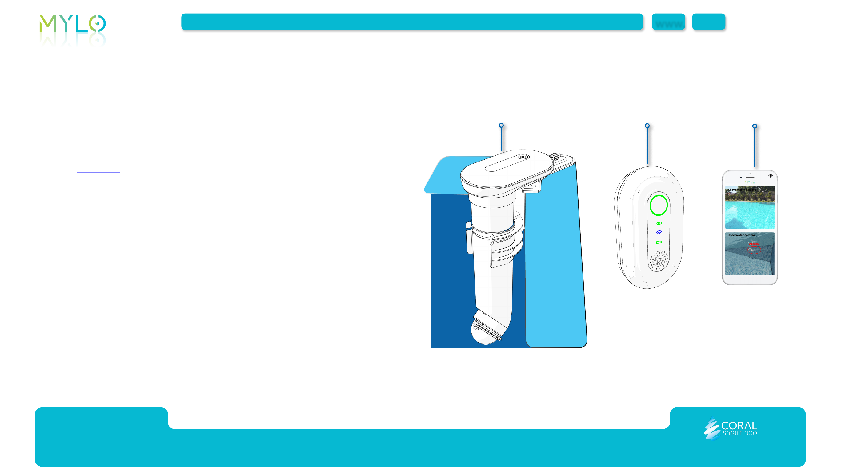
MYLO includes the following:
zPool Unit (1): mounted on a corner of the pool, it includes video
cameras, and generates alerts according to the scenario identified in
the pool (see Detection Scenarios). The pool unit transmits alerts to the
home unit (2) and to the mobile device (3) as needed.
zHome Unit (2): connected to a power outlet in the house, it
communicates with the pool unit over RF (direct) communication, and
provides audio and visual indication of the alerts received from the pool
unit.
zMobile Application (3): the MYLO mobile application, installed on a
mobile device (3), provides alerts, system status notifications and
remote monitoring.
1 2 3
Introduction | System Layout
7.
MENU
www.
INTRODUCTION INITIAL INSTALLATION ROUTINE OPERATION MAINTENANCE TROUBLESHOOTING SPECIFICATIONS MYLO | User Guide Rev A |

Pool Unit
Overview
The pool unit includes the following:
zIndicators and Button (1)
zAbove-water Camera (2)
zActivity Sensor (3)
zUnderwater Camera (4)
zSiren (5)
zDocking Station (6)
6
4
2
3
1
1
5
Introduction | Pool Unit
8.
MENU
www.
INTRODUCTION INITIAL INSTALLATION ROUTINE OPERATION MAINTENANCE TROUBLESHOOTING SPECIFICATIONS MYLO | User Guide Rev A |

Indicators and Buttons
The side indicators (1) provide visual indications of the different scenarios in
the pool. See Detection Scenarios for more information.
The upper indicators (2) are usually off and will turn red only when signs of
drowning are detected. In this case, the alarm (4) will sound.
The dismiss alarm button (3) has the following operations:
zDismiss Alarm: short press up to 5 seconds to silence the alarm (in case
of a false alarm).
zReset: press and hold for 5 seconds to reset the system.
zPower Off: press and hold for 10 seconds to turn off the system. (Use
only before uninstalling the system).
3
2
1
1
4
NOTE:
ONLY FOR WINTER STORAGE:
Power OFF: long press (more than 10 seconds)
Power ON: press to activate.
Introduction | Pool Unit
9.
MENU
www.
INTRODUCTION INITIAL INSTALLATION ROUTINE OPERATION MAINTENANCE TROUBLESHOOTING SPECIFICATIONS MYLO | User Guide Rev A |

Power Supply
The pool unit includes:
zDC IN (1) –power supply cord inlet
zPower Supply Cord (2)
WARNING:
The system does not work without a connected power supply.
Keep the system connected at all times.
21
Introduction | Pool Unit
10.
MENU
www.
INTRODUCTION INITIAL INSTALLATION ROUTINE OPERATION MAINTENANCE TROUBLESHOOTING SPECIFICATIONS MYLO | User Guide Rev A |

Docking Station
The docking station is mounted on a corner of the pool, (see Selecting
the Mounting Position) and serves as a base for the pool unit. After first
installation of the docking station (see Mounting the Docking Station), the
pool unit can be installed or removed quickly. The docking station includes
the following:
zDocking Station Base (1) - attached to the surface with two screws.
zBase Plate Cover (3) – covers the screws.
zScrews (2) – two screws to secure the docking station to the selected
corner of the pool.
2
3
1
Introduction | Pool Unit
11.
MENU
www.
INTRODUCTION INITIAL INSTALLATION ROUTINE OPERATION MAINTENANCE TROUBLESHOOTING SPECIFICATIONS MYLO | User Guide Rev A |

Home Unit
The home unit is plugged into a power outlet inside the user's home and
includes the following:
zPlug (1) – connects to a power outlet inside the house.
zPool Activity Indicator (2) – provides visual indication of the different
scenarios in the pool, see Detection Scenarios.
zLED Indicators (3) – provide indication of the system operation -
connectivity, power, and visibility, see Home Unit Indicators.
zBuzzer (4) – provides auditory indication of different scenarios in the
pool, see Detection Scenarios.2
3
4
1
Introduction | Home Unit
12.
MENU
www.
INTRODUCTION INITIAL INSTALLATION ROUTINE OPERATION MAINTENANCE TROUBLESHOOTING SPECIFICATIONS MYLO | User Guide Rev A |

Home Unit Indicators
Water Visibility Indicator (1)
The water visibility indicator (1) provides the following indications of water
clarity:
zSteady green – clear water
zSteady yellow – there is some visibility degradation
zSteady red – there is significant visibility degradation
Communication Indicator (2)
The communication indicator (2) provides the following indications of connectivity:
zSteady blue – the pool unit is connected to the Internet
zBlinking blue – no Internet connection in the pool unit
Pool Unit Power Indicator (3)
The pool unit indicator (3) should always appear steady green indicating
power is supplied to the pool unit.
1
2
3
Introduction | Home Unit
13.
MENU
www.
INTRODUCTION INITIAL INSTALLATION ROUTINE OPERATION MAINTENANCE TROUBLESHOOTING SPECIFICATIONS MYLO | User Guide Rev A |

Mobile Application
The MYLO by Coral Smart Pool mobile application is available on the
Google Play Store and on the Apple App Store.
The mobile application receives alerts from the MYLO device and produces
notifications on the mobile device.
The mobile application allows the user to retrieve images of the pool,
dismiss alerts, and receive notifications of visibility and connectivity.
Introduction | Mobile Application
14.
MENU
www.
INTRODUCTION INITIAL INSTALLATION ROUTINE OPERATION MAINTENANCE TROUBLESHOOTING SPECIFICATIONS MYLO | User Guide Rev A |

Initial Installation
This chapter provides installation instructions and includes:
zOpening the Box
zSelecting the Mounting Position
zSelecting the Mounting Orientation
zMounting the Docking Station
zInserting the Unit into the Docking Station
zConnecting the Unit to Power
zConnecting the Home Unit
zDownloading the MYLO Application
Initial Installation |
15.
MENU
www.
INTRODUCTION INITIAL INSTALLATION ROUTINE OPERATION MAINTENANCE TROUBLESHOOTING SPECIFICATIONS MYLO | User Guide Rev A |

Opening the Box
The MYLO package includes the following:
DESCRIPTION QTY
Pool Unit 1
Home Unit 1
Docking Station and Plastic Cover 1
Power Cord 1
Accessories Pack 1
Quick Start Guide 1
Initial Installation | Opening the Box
16.
MENU
www.
INTRODUCTION INITIAL INSTALLATION ROUTINE OPERATION MAINTENANCE TROUBLESHOOTING SPECIFICATIONS MYLO | User Guide Rev A |

Selecting the Mounting Position
Select the mounting position according to the following guidelines:
zPool size and dimensions comply with system requirements (see Coral
website).
zCamera line of sight covers the entire pool area (the camera has a field
of view of 110°).
zDistance between the home unit and the pool unit should not exceed 50
yards.
zThe docking station mounting screws should be anchored. For more
information, see Mounting the Docking Station.
zThe pool water level should reach at least the minimum mark on the
underwater tube once it is inserted into the pool.
Initial Installation | Selecting the Mounting Position
17.
MENU
www.
INTRODUCTION INITIAL INSTALLATION ROUTINE OPERATION MAINTENANCE TROUBLESHOOTING SPECIFICATIONS MYLO | User Guide Rev A |

Selecting the Mounting Orientation
The docking station must be mounted, depending on pool size, in the best
location for drowning detection. The selected location must have a field of
view of 110°, and a pool edge ready for drilling and fastening two mounting
holes. Select one of the following mounting orientations:
zFor a pool that has a round or straight edge (1).
zWhen mounting the unit on the corner of the pool, use the straight
mounting (2). If the surface of the pool's edge is not conducive for
drilling of the two holes, use the rotated mounting option (3).
2
110
°
CORNER MOUNTING (STRAIGHT)
110°
CORNER MOUNTING (ROTATED)
3
110°
1
ROUND OR STRAIGHT WALL
Initial Installation | Selecting the Mounting Orientation
18.
MENU
www.
INTRODUCTION INITIAL INSTALLATION ROUTINE OPERATION MAINTENANCE TROUBLESHOOTING SPECIFICATIONS MYLO | User Guide Rev A |

Mounting the Docking Station
After the optimal location for the pool unit has been chosen, perform the
following to install the docking station:
A. Place the docking station on the selected wall of the pool that has
a 110° field of view.
B. Verify that the metal vertical part (3) touches the inner wall of the
pool.
C. Mark the location of the screws (1).
D. Drill two 8mm (5/16”) holes (2).
1
2
3
NOTE:
Images here are for illustration only and depict the installation of
the docking station in the corner of the pool.
Mount the unit according previous pages (see Selecting the
Mounting Position).
Initial Installation | Mounting the Docking Station
19.
MENU
www.
INTRODUCTION INITIAL INSTALLATION ROUTINE OPERATION MAINTENANCE TROUBLESHOOTING SPECIFICATIONS MYLO | User Guide Rev A |

A. Place two screw anchors (4) in the holes (5).
B. Attach the docking station (3) using two screws (2).
C. Attach the base plate cover (1).
1
2
3
4
5
Initial Installation | Mounting the Docking Station
20.
MENU
www.
INTRODUCTION INITIAL INSTALLATION ROUTINE OPERATION MAINTENANCE TROUBLESHOOTING SPECIFICATIONS MYLO | User Guide Rev A |