Corghi SP 2000 Guide

SP 2000
Cod.4-103375 - 1.0 del 03/05
Italiano Manuale d’uso + pezzi di ricambio
English Operator’s manual + spare parts
Français Manuel d’utilisation + rechange
Deutsch Betriebsanleitung + Ersatzteillisten
Español Manual de uso + repuestos

2
DATI TECNICI
Larghezza cerchio min.5” max.14”
Diametro cerchio min.10” max.26”
Diametro max copertura 1100 mm
Forza stallonatura su rullo Kg 700 a 10 BAR
Pressione di esercizio 10 BAR
Peso 48Kg
INSTALLAZIONE
ATTENZIONE
Scollegare la rete elettrica e la linea pneumatica.
Eseguire con attenzione le operazioni di sballatura,
montaggio, sollevamento e installazione di seguito
descritte.
L’inosservanza di tali raccomandazioni può provo-
care danneggiamenti alla macchina e pregiudi-
care la sicurezza dell’operatore.
❏ Smontare la protezione palo C (fig.3).
❏ Svitare la vite A ed eliminare la rondella B (Fig.3).
❏ Scollegare e memorizzare la posizione dei tubi
sul gruppo filtro regolatore lubrificatore, poi
smontare lo stesso gruppo FRL e il portagrasso.
TECHNICAL SPECIFICATIONS
Rim width from 5" to 14"
Rim diameter from 10" to 26"
Max wheel diameter 1100 mm
Bead breaking force on roller 700 kg at 10 bar
Working pressure 10 bar
Weight 48 kg
INSTALLATION
WARNING
Disconnect the electricity and compressed air supplies.
Take care when unpacking, assembling, lifting and
installing the machine during the operations
described below.
Failure to observe these instructions can damage
the machine and cause serious injury or death to
the operator.
❏ Remove the guarding from the tower C (fig.3).
❏ Unscrew screw A and remove washer B (fig.3).
❏ Disconnect and memorise the position of the
pipelines on the filter regulator-lubricator unit,
then remove the FRL unit and the grease cup.
CARACTERISTIQUES TECHNIQUES
Largeur de la jante mini. 5" maxi. 14"
Diamètre de la jante mini. 10" maxi. 26"
Diamètre maxi du revêtement 1100 mm
Force de décollage sur rouleau Kg. 700 à 10 BARS
Pression de service 10 BARS
Poids 48 Kg
INSTALLATION
ATTENTION
Interrompre l’alimentation électrique et pneumatique.
Effectuer minutieusement les opérations de
balourd, de montage, de décollage et
d’installation décrites ci-après.
Le non respect de ces recommandations peut
endommager la machine et compromettre la
sécurité de l’opérateur.
❏ Démonter la protection de la colonne C (Fig.3).
❏ Dévisser la vis A et enlever la rondelle B (Fig. 3).
❏ Séparer les tuyaux et mémoriser leur position sur
le groupe filtre régulateur et lubrificateur, puis
démonter ce groupe FRL et le porte-graisse.
TECHNISCHE DATEN
Felgenbreite min 5" max 14"
Felgendurchmesser min 10" max 26"
Reifendurchmesser max 1100 mm
Abdrückkraft/Rolle 700 kg bei 10 bar
Betriebsdruck 10 bar
Gewicht 48 kg
AUFSTELLUNG
ACHTUNG
Die Strom- und Druckluftversorgung unterbrechen.
Nachstehende Auspack-, Montage-, Hub- und
Aufstellhinweise befolgen.
Die Mißachtung derselben kann Schäden an der
Maschine bewirken und die Sicherheit des
Bedienerpersonals in Gefahr setzen.
❏ Säulenschutz C (Abb. 3) abnehmen.
❏ Schraube A abdrehen und Scheibe B (Abb. 3)
weglegen.
❏ Die Leitungen von den Anschlüssen an der Filter-
Regel-Schmiersystem-Gruppe abnehmen, deren
Position notieren und anschließend die FRS-
Gruppe sowie die Fettaufnahme abmontieren.
DATOS TÉCNICOS
Ancho llantamín. 5" máx. 14"
Diámetro llantamín. 10" máx. 26"
Diámetro máx. cubierta 1100 mm
Fuerza de destalonamiento en el rodillo 700 kg a 10 bares
Presión de funcionamiento 10 bares
Peso 48 kg
INSTALACIÓN
Atención
Desconectar la red eléctrica y la línea neumática.
Realizar con extremo cuidado las operaciones de
desembalaje, elevación e instalación que se
describen más adelante.
La inobservancia de dichas instrucciones puede
ocasionar daños a la máquina y comprometer la
seguridad del operador.
❏ Desmontar la protección de la columna C (fig. 3).
❏ Aflojar el tornillo A y quitar la arandela B (fig. 3).
❏ Desconectar y memorizar la posición de los
tubos en el grupo filtro regulador + lubricador y a
continuación desmontar el grupo FRL mismo y el
depósito para grasa.

3
Fig. 1
C
A
B
E
F
G
D (FRL)
Fig. 3
Fig. 2
L
M
N

4
❏ Inserire la vite E (fig.3), il dado e la rosetta G.
❏ Inserire il montante F (fig.3) e rimontare la vite A
(non rimontare la rondella B precedentemente
eliminata).
❏ Fissare il montante F sulla trave stallonatore con
le viti L, il blocchetto M e i dadi N (fig.3).
❏ Prendere tutto il gruppo stallonatore F e inserirlo
sul montante A (fig.4).
Fissare il gruppo stallonatore F sul montante A:
con viti G, rimontando il portagrasso, e con vite
e dadi H sulla parte superiore del montante
fissando anche il supporto S (fig.4).
❏ Montare il braccio alzatalloni I (fig.4) (Vedi lo
schema di montaggio mensola alzatalloni).
❏ Montare il gruppo FRL e la protezione palo C
come in fig.3.
CIRCUITO PNEUMATICO
❏Collegare i tubi e i raccordi come da figura 5.
❏ Fit screw E (fig.3), and nut/washer G.
❏ Fit support F (fig.3) and refit screw A (but not
washer B removed earlier).
❏ Fix the upright F on the bead breaker beam with
the screws L, the block M and the nuts N (fig.3).
❏ Take the bead-breaker unit F and secure it to
support A, (fig.4).
Fix the bead breaker unit F on the upright A:
with screws G, putting the grease cap back in
place, and with screws H on the top of the
upright, also fixing the support S (fig.4).
❏ Fit the bead lifting arm I (fig.4) (see bead lifting
support assembly diagram).
❏ Fit unit FRL and tower guard C as shown in
figure 3.
PNEUMATIC CIRCUIT
❏Connect up the hoses and connectors as in fig.5.
❏ Introduire la vis E (Fig.3), l’écrou et la rosette G.
❏ Introduire le montant F (Fig.3), puis remonter la
vis A (ne pas remettre la rondelle B).
❏ Fixer le montant F sur la poutre du détalonneur
avec les vis L, le bloc M et les écrous N (fig.3).
❏ Prendre le groupe démonte-pneu F et
l’introduire sur le montant A (Fig.4).
Fixer le groupe détalonneur F sur le montant A␣ :
avec les vis G, en remontant le porte-graisse, et
avec la vis et les écrous H sur la partie supérieure
du montant en fixant aussi le support S (fig.4).
❏ Monter le bras lève-talons I (Fig.4) (voir schéma
de montage de la barre lève-talons).
❏ Monter le groupe FRL et la protection de la
colonne C comme indiqué sur la Fig. 3.
CIRCUIT PNEUMATIQUE
❏Raccorder les tuyaux et les raccords comme
indiqué à la fig.5.
❏ Schraube E (Abb. 3) eindrehen, Mutter und
Scheibe G anbringen.
❏ Säule F (Abb. 3) einsetzen, Schraube A (nicht die
vorab entfernte Scheibe B).
❏ Den Ständer F mit den Schrauben L, dem Block
M und den Muttern N am Reifenabdrückträger
befestigen (Abb. 3).
❏ Komplette Abdrückaggregat F auf Ständer A
(Abb. 4) einstecken.
DieReifenabdrückgruppeFamStänderAbefestigen:
anhand der Schrauben G zusammen mit der
Fettaufnahme und anhand der Schraube und
Muttern H im oberen Bereich des Ständers, wobei
auch die Halterung S zu befestigen ist (Abb. 4).
❏ Hubarm I (Abb. 4) gemäß Einbauanleitungen
Abdrückkonsole) montieren.
❏ FRL Aggregat mit Säulenschutz lt. Abb. 3
einbauen.
PNEUMATIKKREIS
❏Die Verbindung der Rohre und Anschlüsse
gemäß Abb.5 vornehmen.
❏Insertar el tornillo E (fig. 3), latuerca y la arandela G.
❏ Insertar el montante F (fig. 3) y volver a colocar el
tornillo A (sin reponer la arandela B previamente
extraída).
❏ Fijar el montante F en el travesaño destalonador
mediante los tornillos L, el bloque M y las tuercas
N (fig. 3).
❏ Insertar todo el grupo destalonador F en el
montante A (fig. 4).
Fijar el grupo destalonador F en el montante A:
mediante los tornillos G, reinstalando el depósito
para grasa, y mediante tornillo y tuercas H en la
parte superior del montante, fijando también el
soporte S (fig. 4).
❏ Montar el brazo levanta-talón I (fig. 4). (Ver
Esquema de montaje de la ménsula levanta-
talón.)
❏ Montar el grupo FRL y la protección de la
columna C como se indica en la fig. 3.
CIRCUITO NEUMÁTICO
❏Conectar los tubos y los empalmes pal como se
ilustra en la figura 5.

5
1234567890123456789012345678901212345678901234567890123456789012123456789012345678901234567890121234
1
23456789012345678901234567890121234567890123456789012345678901212345678901234567890123456789012123
4
1
23456789012345678901234567890121234567890123456789012345678901212345678901234567890123456789012123
4
1
23456789012345678901234567890121234567890123456789012345678901212345678901234567890123456789012123
4
1
23456789012345678901234567890121234567890123456789012345678901212345678901234567890123456789012123
4
1
23456789012345678901234567890121234567890123456789012345678901212345678901234567890123456789012123
4
1
23456789012345678901234567890121234567890123456789012345678901212345678901234567890123456789012123
4
1
23456789012345678901234567890121234567890123456789012345678901212345678901234567890123456789012123
4
1
23456789012345678901234567890121234567890123456789012345678901212345678901234567890123456789012123
4
1
23456789012345678901234567890121234567890123456789012345678901212345678901234567890123456789012123
4
1
23456789012345678901234567890121234567890123456789012345678901212345678901234567890123456789012123
4
1
23456789012345678901234567890121234567890123456789012345678901212345678901234567890123456789012123
4
1
23456789012345678901234567890121234567890123456789012345678901212345678901234567890123456789012123
4
1
23456789012345678901234567890121234567890123456789012345678901212345678901234567890123456789012123
4
1
23456789012345678901234567890121234567890123456789012345678901212345678901234567890123456789012123
4
1
23456789012345678901234567890121234567890123456789012345678901212345678901234567890123456789012123
4
1
23456789012345678901234567890121234567890123456789012345678901212345678901234567890123456789012123
4
1
23456789012345678901234567890121234567890123456789012345678901212345678901234567890123456789012123
4
1
23456789012345678901234567890121234567890123456789012345678901212345678901234567890123456789012123
4
1
23456789012345678901234567890121234567890123456789012345678901212345678901234567890123456789012123
4
1
23456789012345678901234567890121234567890123456789012345678901212345678901234567890123456789012123
4
1
23456789012345678901234567890121234567890123456789012345678901212345678901234567890123456789012123
4
1
23456789012345678901234567890121234567890123456789012345678901212345678901234567890123456789012123
4
1
23456789012345678901234567890121234567890123456789012345678901212345678901234567890123456789012123
4
1
23456789012345678901234567890121234567890123456789012345678901212345678901234567890123456789012123
4
1
23456789012345678901234567890121234567890123456789012345678901212345678901234567890123456789012123
4
1
23456789012345678901234567890121234567890123456789012345678901212345678901234567890123456789012123
4
1
23456789012345678901234567890121234567890123456789012345678901212345678901234567890123456789012123
4
1
23456789012345678901234567890121234567890123456789012345678901212345678901234567890123456789012123
4
1
23456789012345678901234567890121234567890123456789012345678901212345678901234567890123456789012123
4
1
23456789012345678901234567890121234567890123456789012345678901212345678901234567890123456789012123
4
1
23456789012345678901234567890121234567890123456789012345678901212345678901234567890123456789012123
4
1
23456789012345678901234567890121234567890123456789012345678901212345678901234567890123456789012123
4
1
23456789012345678901234567890121234567890123456789012345678901212345678901234567890123456789012123
4
1
23456789012345678901234567890121234567890123456789012345678901212345678901234567890123456789012123
4
1
23456789012345678901234567890121234567890123456789012345678901212345678901234567890123456789012123
4
1
23456789012345678901234567890121234567890123456789012345678901212345678901234567890123456789012123
4
1
23456789012345678901234567890121234567890123456789012345678901212345678901234567890123456789012123
4
1
23456789012345678901234567890121234567890123456789012345678901212345678901234567890123456789012123
4
1
23456789012345678901234567890121234567890123456789012345678901212345678901234567890123456789012123
4
1
23456789012345678901234567890121234567890123456789012345678901212345678901234567890123456789012123
4
1
23456789012345678901234567890121234567890123456789012345678901212345678901234567890123456789012123
4
1
23456789012345678901234567890121234567890123456789012345678901212345678901234567890123456789012123
4
1
23456789012345678901234567890121234567890123456789012345678901212345678901234567890123456789012123
4
1
23456789012345678901234567890121234567890123456789012345678901212345678901234567890123456789012123
4
1
23456789012345678901234567890121234567890123456789012345678901212345678901234567890123456789012123
4
1
23456789012345678901234567890121234567890123456789012345678901212345678901234567890123456789012123
4
1
23456789012345678901234567890121234567890123456789012345678901212345678901234567890123456789012123
4
1
23456789012345678901234567890121234567890123456789012345678901212345678901234567890123456789012123
4
1
23456789012345678901234567890121234567890123456789012345678901212345678901234567890123456789012123
4
1
23456789012345678901234567890121234567890123456789012345678901212345678901234567890123456789012123
4
1
23456789012345678901234567890121234567890123456789012345678901212345678901234567890123456789012123
4
1
23456789012345678901234567890121234567890123456789012345678901212345678901234567890123456789012123
4
1
23456789012345678901234567890121234567890123456789012345678901212345678901234567890123456789012123
4
1
23456789012345678901234567890121234567890123456789012345678901212345678901234567890123456789012123
4
1
23456789012345678901234567890121234567890123456789012345678901212345678901234567890123456789012123
4
1
23456789012345678901234567890121234567890123456789012345678901212345678901234567890123456789012123
4
1
23456789012345678901234567890121234567890123456789012345678901212345678901234567890123456789012123
4
1
23456789012345678901234567890121234567890123456789012345678901212345678901234567890123456789012123
4
1
23456789012345678901234567890121234567890123456789012345678901212345678901234567890123456789012123
4
1234567890123456789012345678901212345678901234567890123456789012123456789012345678901234567890121234
A
B
C
E
D
F
Fig. 4
A
H
I
F
G
Fig. 5
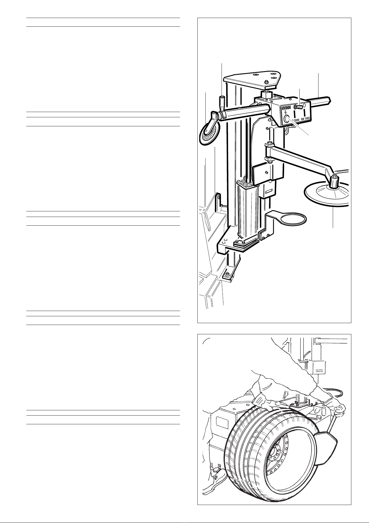
Schemadimontaggiomensolaalzatalloni
❏Inserire la mensola alzatalloni A e la
rondella elastica B.
❏Allineare i fori con il perno inseritore C.
❏Introdurre la vite D per espellere il perno
inseritore.
❏Serrare con la rondella E e il dado F.
Instructions for installing the bead-
breaker support
❏ Fit bead breaker support “A” and
spring washer “B”.
❏ Align the holes with the inserter pin “C”.
❏ Insert screw “D” and use it to push the
inserter pin out.
❏ Tighten screw “D” with the nut “F”
after having fitted washer “E”.
Schéma montage barre lève-talons
❏ Introduire la barre lève-talons A et la
rondelle en caoutchouc B.
❏ Aligner les orifices dans l’axe du pivot
d’introduction C.
❏ Introduire la vis D pour expulser le
pivot d’introduction.
❏ Serrer avec la rondelle E et l’écrou F.
Einbauanleitung Abdrückerhubarm
❏ Abdrückerhubarm A und
Sprengscheibe B einsetzen
❏ Bohrungen durch Spitzdorn C
ausrichten
❏ Mit Schraube D den Spitzdorn
ausschieben
❏ Den Einbau durch Festziehen von
Gegenscheibe E und Mutter F
abschließen.
Esquema de montaje de la ménsula
levanta-talón
❏ Introducir la ménsula levanta-talón A
y la arandela elástica B.
❏ Alinear los orificios con el perno
pasante C.
❏ Insertar el tornillo D para expulsar el
perno pasante.
❏ Ajustar con la arandela E y la tuerca F.
S

6
AVVERTENZE
Per operare correttamente con questa macchina
è necessario: conoscerne le capacità e le caratte-
ristiche, non togliere o modificare nessuna parte di
questa macchina (eccetto per assistenza) e
mantenere il personale non autorizzato lontano
dall’apparecchiatura durante il lavoro.
Alcune illustrazioni contenute in questo libretto
sono state ricavate da foto di prototipi; le macchi-
ne della produzione standard possono differire in
alcuni particolari.
WARNINGS
To ensure proper use of the machine the operator
must: have a thorough knowledge of the
machine’s capacity and features: never remove or
alter any parts of the machine (except in for
service) and keep unauthorized persons well clear
of the machine when it is being used.
Some of the illustrations in this handbook are
photographs of prototype machines. Standard
production machines may differ in certain
respects.
Keep this manual in a safe place and consult it
regularly.
MAIN PARTS (Fig.6)
1. Bead-breaker disk.
2. Horizontal arm.
3. Horizontal arm movement handle.
4. Arm locking button.
5. Up-down control lever.
6. Bead lifter disk.
AVERTISSEMENT
Pour travailler correctement avec cette machine il
faut: en connaître les capacités et les
caractéristiques, ne retirer ni modifier aucune de
ses parties (sauf en cas d’assistance) et empêcher
le personnel non autorisé de s’approcher de
l’appareil pendant le travail.
Certaines illustrations figurant dans ce livret se
réfèrent à des prototypes; les machines standard
de la production peuvent être quelque peu
différentes.
Ranger soigneusement ce livret et ne pas oublier
de le consulter régulièrement.
PIECES PRINCIPALES (Fig.6)
1. Disque détalonneur.
2. Bras horizontal.
3. Levier bras horizontal.
4. Poussoir de blocage.
5. Manette commande descente-montée.
6. Disque lève-talon.
HINWEISE
Für den vorschriftsmäßigen Maschinenbetrieb ist
folgendes erforderlich: die Kenntnis der Leistungen
und die Eigenschaften der Maschine, es darf kein
Maschinenteil abmontiert oder geändert werden
(es sei denn für Wartungsarbeiten) und Unbefugtes
Personal muß auf Sicherheitsabstand bleiben.
Einige Abbildungen dieser Anleitung sind aus
Photos von Prototypen der Maschine entstanden;
die Maschinen der Serienproduktion können in
einigen Merkmalen davon abweichen.
Bewahren Sie diese Anleitung sorgfältig als
wertvolle Arbeitshilfe auf.
HAUPTTEILE (Fig.6)
1. Abdrückerscheibe.
2. Waagerechter Arm.
3. Griff waagerechter Arm.
4. Arretierknopf.
5. Steuerhebel Auf/Ab.
6. Wulstheberscheibe.
ADVERTENCIAS
Para operar correctamente con esta máquina, es
necesario conocer sus prestaciones y
características. No extraer ni modificar ninguna
parte de la máquina (excepto por motivos de
asistencia) y no permitir que personal no
autorizado se acerque a ella durante el trabajo.
Algunas de las ilustraciones de este manual se han
tomado de fotos de prototipos: las máquinas de
producción estándar pueden diferir de ellas en
algunos detalles.
Conservar cuidadosamente este manual y consul-
tarlo regularmente.
PARTES PRINCIPALES (Fig. 6)
1. Disco destalonador.
2. Brazo horizontal.
3. Manija brazo horizontal.
4. Pulsador de bloqueo.
5. Palanca de mando de bajada y subida.
6. Disco alza-talón.
Conservare accuratamente questo manuale e
non trascurare di consultarlo regolarmente.
PARTI PRINCIPALI (Fig. 6)
1. Disco stallonatore.
2. Braccio orizzontale.
3. Maniglia braccio orizzontale.
4. Pulsante di blocco.
5. Leva comando discesa salita.
6. Disco alzatallone.

7
Fig. 7
FUNZIONE STALLONATORE
Utilizzo consigliato in presenza di cerchi in lega
particolarmente difficili o delicati:
❏Stallonare il bordo interno del cerchione con lo
stallonatore a paletta laterale (Fig.7).
❏Posizionare il disco stallonatore dell’SP2000
in senso orizzontale: manualmente
in senso verticale: con la leva del rubinetto
Il disco stallonatore va posizionato a circa 4-5
mm dal bordo cerchione e appoggiato sul
fianco copertura. (Fig.9)
BEAD-BREAKER FUNCTION
Use the SP2000 bead-breaker in the case of
particularly difficult or delicate alloy rims:
❏ Break the lower bead of the rim using standard
side bead-breaker shoe (Fig.7)
❏ Position the SP2000 bead-breaker disk:
horizontal positioning is performed manually, vertical
positioning is done using the pneumatic control lever.
The bead-breaker disk must be positioned 4-5
mm from the edge of the rim and rested against
the wall of the tyre (Fig.9)
FONCTION DU DEMONTE-PNEU
Utilisation conseillée avec des jantes en alliage
particulièrement difficiles ou délicates:
❏Décoller le bord intérieur de la jante avec le
décolleur à pelle latéral (Fig.7).
❏Positionner le disque détalonneur du SP2000 à
l’horizontale: manuellement;
à la verticale: avec le levier du bras.
Le disque détalonneur se place à environ 4-5
mm du bord de la jante et s’appuie sur le côté
du pneu. (Fig.9)
ABDRÜCKERFUNKTION
Gebrauchsanweisung bei besonders schwierigen
oder empfindlichen Leichtmetallfelgen:
❏Den Innenrand der Felge mit der seitlichen
Abdrückschaufel abdrücken. (Abb.7)
❏Den Spannflansch SP2000 waagrecht stellen:
manuell Senkrecht stellen: mit dem Ventilhebel
Die Abdrückscheibe wird in ca. 4-5mm Abstand
zur Felgenkante in Stellung gebracht und am
Reifenrand angesetzt (Abb.9).
FUNCIÓN DEL DESTALONADOR
Se aconseja su uso para llantas de aleación
particularmente difíciles o delicadas:
❏Destalonar el borde interno de la llanta con el
destalonador de paleta lateral (Fig. 7).
❏Colocar el disco destalonador SP2000 en sentido
horizontal manualmente, y en sentido vertical
mediante la palanca del grifo.
El disco destalonador se coloca a unos 4-5 mm
del borde de la llanta, apoyado sobre el
costado de la cubierta (Fig. 9).
Fig. 6
6
2
1
4
5
3

8
❏Bloccare con l’apposito pulsante il dispositivo.
(Fig.9)
❏Far ruotare l’autocentrante e successivamente
abbassare il disco stallonatore con la leva co-
mando “Discesa-Salita”. (Fig.10)
Insistere con la rotazione e la leva del rubinetto
fino a stallonatura avvenuta (il disco ha una
corsa verticale utile di 60 mm.)
❏Agendo sulla leva in senso contrario, si procede
al disimpegno del disco e allo sbloccaggio
automatico del meccanismo.
NOTA: Insistere sulla leva fino al completo disim-
pegno del disco stallonatore.
NB: L’SP2000 può essere convenientemente utiliz-
zato durante la fase di montaggio del 2°tallone di
un pneumatico.
E’ sufficiente posizionare il disco stallonatore a 20-
30 mm sotto il bordo del cerchione prima di proce-
dere all’intallonatura del 2°tallone. (Fig.11)
Questa operazione agevola l’entrata del tallone
nel canale del cerchione stesso.
❏ Press the lock button to clamp the unit in position
(Fig.9)
❏ Start the table top turning and then lower the
bead-breaker disk using the pneumatic control
lever (Fig.10).
Keep turning the table top and the keep the
control lever pressed until the bead has
completely detached (the disk has an effective
vertical stroke of 60 mm)
❏ Turn the lever in the opposite direction to bring
the disk away from the tyre. The clamping
mechanism will unlock automatically.
NOTE: keep the lever turned until the bead
breaker disk is completely clear of the work area.
NB: The SP2000 can also prove useful for seating
the 2nd bead of the tyre.
Simply position the bead-breaker disk 20 or 30 mm
under the edge of the rim before seating the 2nd
bead (Fig.11).
This will help guide the bead into the drop centre
of the wheel.
❏Bloquer le dispositif à l’aide du poussoir. (Fig.9)
❏Faire tourner le plateau centreur, puis baisser le
disque détalonneur à l’aide du levier de
commande “Descente-Montée”. (Fig.10)
Insister sur la rotation et le levier du bras jusqu’à
ce que le pneu sorte (le disque a une course
verticale de 60 mm.)
❏En agissant sur le levier dans le sens contraire, on
enlève le disque et on débloque
automatiquement le mécanisme.
REMARQUE: Insister sur le levier jusqu’à ce que le
disque détalonneur soit complètement sorti.
NB: Le SP2000 peut être avantageusement utilisé
pendant la phase de montage du 2ème talon
d’un pneu.
Il suffit de placer le disque détalonneur à 20-30 mm
sous le bord de la jante, avant d’effectuer le
décollage du 2ème talon. (Fig.11)
Cette opération facilite l’entrée du talon dans le
creux de la jante.
❏Arretierknopf drücken. (Abb.9)
❏ Spannflansch in Drehung versetzen und
anschließend Abdrückscheibe mit dem
Steuerhebel “Auf-Ab” herablassen. (Abb.10)
Mit der Drehung und dem Festhalten des
Ventilhebels fortfahren, bis der Wulst abgedrückt
ist (die Scheibe hat einen Ist-Senkrechthub von
60mm).
❏Bei Schieben des Hebels in entgegengesetzte
Richtung wird die Scheibe gelöst und die
Blockierung des Vorgangs automatisch
aufgehoben.
MERKE: Hebel bis zur vollständigen Ablösung der
Abdrückscheibe festhalten.
ANMERKUNG: Es kann von Vorteil sein, den SP2000
während der Montage des 2°Reifenwulstes
anzuwenden.
Es genügt, die Abdrückscheibe 20-30mm unter
dem Felgenhorn anzusetzen bevor die
Abdrückung des zweiten Wulstes vorgenommen
wird. (Abb.11)
Dieser Vorgang beschleunigt das Eindrücken des
Wulstes in das Felgenbett.
❏Bloquear el dispositivo mediante el respectivo
pulsador (Fig. 9).
❏Hacer girar el dispositivo autocentrante y, a
continuación, bajar el disco destalonador con la
palanca de mando de “Bajada-Subida” (Fig. 10).
Insistir con la rotación y la palanca del grifo
hasta destalonar la cubierta (el disco tiene una
carrera vertical útil de 60 mm).
❏Al accionar la palanca en sentido contrario se
libera el disco y se desbloquea
automáticamente el mecanismo.
NOTA: insistir con la palanca hasta que el disco
destalonador se libere por completo.
NOTA: El SP2000 puede utilizarse convenientemen-
te durante la fase de montaje del segundo talón
de un neumático.
Para ello es suficiente colocar el disco
destalonador a 20-30 mm por debajo del borde
de la llanta antes de proceder al montaje del
segundo talón (Fig. 11).
Esta operación facilita la entrada del talón en el
canal de la llanta.

9
Fig. 9
Fig. 11
Fig. 10

10
FUNZIONE SOLLEVATORE
In presenza di coperture di grande spessore o
pesanti, dopo avere sfilato il 1°tallone, procedere
nel seguente modo:
❏Inserire la mensola alzatallone sotto il fianco
inferiore della copertura.
❏Azionando la leva rubinetto, alzare la copertura
all’altezza desiderata. (Fig.12)
❏Procedere allo smontaggio del 2°tallone con il
sistema tradizionale.
Nel caso si voglia stallonare anche il bordo interno
della ruota con il disco stallonatore, operare come
segue:
❏Bloccare dalla parte interna la ruota
sull’autocentrante.
❏Stallonare il bordo superiore.
❏Sbloccare la ruota e ribloccarla dal bordo già
stallonato con presa dall’esterno.
❏Stallonare il bordo superiore.
❏Se la ruota così stallonata (da ambo i lati) à un
cerchio con canale rovescio procedere allo
smontaggio; se il canale è dalla parte esterna,
BEAD LIFTING ARM FUNCTION
If the tyre is particularly heavy gauge or heavy
weight, after you have broken the first bead
proceed as follows:
❏ Fit the bead lifting arm under the bottom wall of
the tyre
❏ Raise the pneumatic control lever to lift the tyre
to the desired height (Fig.12)
❏ Remove the 2nd bead using the conventional
system.
If you wish to unseat also the internal bead of the
wheel with the bead-breaker disk, proceed as
follows:
❏ Clamp the wheel to the table top from the
inside.
❏ Break the upper bead.
❏ Release the wheel and re-install it on the side on
which the bead has just been broken, but this
time clamp it from the outside.
❏ Break the upper bead.
❏ When you have broken the bead on both sides,
if the wheel has a reverse drop centre proceed
FONCTION DECOLLAGE
Avec un revêtement très épais ou lourd, après
avoir retiré le 1er talon, procéder comme suit:
❏Introduire le support décolleur sous le bord
inférieur du pneu.
❏En actionnant le levier bras, décoller le pneu à la
hauteur voulue. (Fig.12)
❏Démonter le 2ème talon avec le système
traditionnel.
Si l’on veut aussi décoller le talon intérieur de la
roue à l’aide du disque détalonneur, il faut
procéder comme suit:
❏bloquer la roue, de l’intérieur, sur le plateau
tournant.
❏Décoller le bord supérieur.
❏Débloquer la roue et la rebloquer sur la partie
déjà décollée, de l’extérieur.
❏Décoller le bord supérieur.
❏Si la roue, ainsi décollée (des deux côtés), à une
jante avec un creux à l’envers procéder au
démontage; si le creux se trouve sur la partie
WULSTANHEBERFUNKTION
Bei breiten oder schweren Reifen, nachdem der 1°
Wulst abgedrücktist, folgendermaßen vorgehen:
❏Den Wulstanheber am untenliegenden
Reifenrand ansetzen.
❏Den Ventilhebel betätigen und den Reifen auf
die gewünschte Höhe anheben. (Abb.12)
❏2°Wulst auf herkömmliche Weise demontieren.
Falls auch der innere Rand des Reifens mit der
Abdrückscheibe abgedrückt werden soll,
folgendermaßen vorgehen:
❏Das Rad von innen auf dem Spannflansch
blockieren.
❏Den oberen Rand abdrücken.
❏Das Rad lockern und es am schon
abgedrückten Rand von außen blockieren.
❏Den oberen Rand abdrücken.
❏Wenn das derart (beidseitig) abgedrückte Rad
eine Felge mit umgekehrten Bett besitzt, mit der
Demontage beginnen; wenn das Felgenbett der
FUNCIÓN DE ELEVADOR
En presencia de cubiertas de gran espesor o peso,
una vez extraído el primer talón, proceder de la
siguiente manera:
❏Introducir la ménsula levanta-talón bajo la cara
inferior de la cubierta.
❏Mediante la palanca del grifo, levantar la
cubierta a la altura deseada (Fig. 12).
❏Desmontar el segundo talón con el sistema
tradicional.
En el caso en que se desee destalonar también el
borde interno de la rueda con el disco
destalonador, operar como sigue:
❏Bloquear la rueda desde adentro contra el
dispositivo autocentrante.
❏Destalonar el borde superior.
❏Desbloquear la rueda y volver a bloquearla
desde el borde ya destalonado, tomándola
desde afuera.
❏Destalonar el borde superior.
❏Si la rueda ya destalonada (de ambos lados)
tiene una llanta con canal invertido,

11
sbloccare la ruota e bloccarla sul
bordo opposto con presa dall’interno
e successivamente procedere allo
smontaggio.
extérieure, débloquer la roue,puis la rebloquer
sur le bord opposé avec une prise de l’intérieur
et effectuer le démontage.
Außenseite zugekehrt ist, das Rad lockern, dann
es von innen am gegenüberliegenden Rand
blockieren und mit der Demontage beginnen.
desmontarlo. Si el canal está en la parte externa,
desbloquear la rueda y bloquearla sobre el
borde opuesto, tomándola desde adentro, y
entonces proceder al desmontaje.
Fig. 12
to demount the tyre; if the drop centre
is on the outside of the wheel, release
the wheel and re-install it on the
opposite side, clamping it from the
inside before demounting the tyre.

12
A 2019 RC SP 2000Fig. A - 03 / 05
Ø6
5
3
10
11
12
13
63
Ø6
24
68
Ø6
62
6
62
2
8
6
79
17
51
19
21
52
20
23
Ø6
22
13
25
26
27
50
41
13
36
40
Ø6
Ø6
53
55
48
40
13
Ø8
57
56
59
60
67
64
69
70
49

13
A 2019 RC SP 2000Fig. A - 03 / 05
Ø6 900701684 TUBO PIPE ROHR TUYAU
Ø8 900701683 TUBO PIPE ROHR TUYAU
0002 900444511 RACCORDO CONNECTOR ANSCHLUSS RACCORD
0003 900440585 MANOPOLA KNOB BALLENGRIFF BOUTON
0005 900435644 VALVOLA VALVE VENTIL VANNE
0006 900433675 REGOLATORE REGULATOR REGLER REGULATEUR
0007 900444227 VALVOLA VALVE VENTIL VANNE
0008 900332228 TUBO PIPE ROHR TUYAU
0009 900443365 RACCORDO CONNECTOR ANSCHLUSS RACCORD
0010 900422682 SILENZIATORE SILENCER SCHALLDAEMPFER SILENCIEUX
0011 900444510 RACCORDO CONNECTOR ANSCHLUSS RACCORD
0012 900332229 TUBO PIPE ROHR TUYAU
0013 900438664 RACCORDO CONNECTOR ANSCHLUSS RACCORD
0017 263496 MANOPOLA KNOB BALLENGRIFF BOUTON
0019 4-100774 SUPPORTO SUPPORT LAGER SUPPORT
0020 900344200 BLOCCAGGIO LOCKING SPERRE BLOCAGE
0021 950305972 RONDELLA WASHER UNTERLEGSCHEIBE RONDELLE
0022 950406379 MOLLA SPRING FEDER RESSORT
0023 900428388 RACCORDO CONNECTOR ANSCHLUSS RACCORD
0024 900326537 CILINDRO CYLINDER ZYLINDER CYLINDRE
0025 900443077 PISTONE PISTON KOLBEN PISTON
0026 900344201 BLOCCAGGIO LOCKING SPERRE BLOCAGE
0027 900438569 MOLLA SPRING FEDER RESSORT
0036 900344212 PROTEZIONE SHIELD ABDECKUNG PROTECTION
0040 900344205 PERNO PIN ZAPFEN PIVOT
0041 900409650 RONDELLA WASHER UNTERLEGSCHEIBE RONDELLE
0048 900244165 CILINDRO CYLINDER ZYLINDER CYLINDRE
0049 900244156 GUIDA GUIDE FUEHRUNG GLISSIERE
0050 900244157 SCORREVOLE SLIDER SCHIEBER CURSEUR
0051 900244158 CORPO BODY KOERPER CORPS
0052 360379 BRACCIO ARM ARM BRAS
0053 254938 BRACCIO ARM ARM BRAS
0055 900421669 RACCORDO CONNECTOR ANSCHLUSS RACCORD
0056 900447230 RACCORDO CONNECTOR ANSCHLUSS RACCORD
0057 900443431 RACCORDO CONNECTOR ANSCHLUSS RACCORD
0059 900346875 PROTEZIONE SHIELD ABDECKUNG PROTECTION
0062 900443367 RACCORDO CONNECTOR ANSCHLUSS RACCORD
0063 900442276 RACCORDO CONNECTOR ANSCHLUSS RACCORD
0064 263513 RULLO ROLLER WALZE ROULEAU
0067 900240122 KIT GUARNIZIONI SEALS KIT DICHTUNGSATZ KIT JOINTS
0068 358118 SUPPORTO SUPPORT LAGER SUPPORT
0069 344891 BLOCCHETTO BLOCK BLOCK BLOC
0070 4-101862 SUPPORTO SUPPORT LAGER SUPPORT

14
Note

15
Notes

UPT - Cod.4-103375 - Rif.Poz.901000299 - 03/05 - 600.
CORGHI S.p.A. - Via per Carpi, n.9
42015 CORREGGIO - R.E. - ITALY
Tel. ++39 0522 639.111 - Fax ++39 0522 639.150
Table of contents
Other Corghi Industrial Equipment manuals
Popular Industrial Equipment manuals by other brands

OmniMetrix
OmniMetrix Hero 40 Amp Tap Commander installation guide

Siemens
Siemens POWERMOBIL SP Maintenance Instruction

Nissei
Nissei GTR-AR instruction manual

Baelz Automatic
Baelz Automatic BA 373-E45 operating instructions

Panduit
Panduit FiberRunner QuikLock FR12X4 installation instructions

Endress+Hauser
Endress+Hauser Liquistation CSF39 Brief operating instructions

Del Morino
Del Morino RES Use and maintenance manual

AVK
AVK 870 Series Installation, operation and maintenance manual

Aerotech
Aerotech ACS Hardware manual

ABB
ABB HT612773 Operation manual

Bühler technologies
Bühler technologies GAS 222.20 Ex2 Installation and operation instruction

Wadkin
Wadkin GD instruction manual