Del Morino RES User manual

RES-e-12 Use and maintenance manual : RES
Del Morino srl , v.Caroni di Sotto 19,
I-52033 Caprese Michelangelo AR Italy
Ph: +39-575-791059 Fax: +39-575-791210
E.mail: export@del-morino.it
http://www.del-morino.it
USE AND MAINTENANCE MANUAL
BACK HOE TYPE RES

2
PREFACE
This manual is an integral part of the machine
It must always accompany the machine and be kept within reach of the operator.
The enclosures mentioned are on integral part of this manual.
The purpose of this manual
This manual gives information for the correct and safe use of the machine.
The owner must read this manual carefully before work with the machine.
Responsibility of the owner
The owner is responsible for accidents or damages caused to people or things due to negligence in following
the instructions in this manual.
Assistance in using this manual
Explanations: contact the dealer.
Request for additional copies of the manual: in case of loss or wear and tear, or in case one wants the
manual in a different language, the customer should ask the dealer or manufacturer.
Pay attention to the warning signals
<Danger>: indicates a situation that is potentially dangerous which, if not avoided, will cause death or
serious damage.
<Warning>: indicates a situation that is potentially dangerous which, if not avoided, will cause death or
Serious damage.
<Caution>: indicates a situation that is potentially dangerous which, if not avoided, can cause minor to
moderate damage, or it indicates to be careful about an unsafe procedure.
<Important> : indicates instructions that must be followed precisely in order to avoid damage to the product,
process or environment.
<Note>: indicates supplementary information.

3
DESCRIPTION
DESCRIPTION OF THE MACHINE
The back hoes type RES are machines applicable to the rear lifter of agricultural tractors.
The machine is composed with a jointed arm with a bucket mounted at its end. The arm is jointed with a
frame where there are the hand drive and the operator seat. The arm can rotate about 170° and can shift
respect to the frame. All the arms and bucket movement are hydraulic driven. The shifting movement of the
arm respect to the frame is manual with screw locking on RES15-20 and hydraulic locking on RES30-50.
The machine has an independent hydraulic plant driven by a pump connected with a multiplier to the reap
PTO of the tractor.
USE OF THE MACHINE
The back hoe type RES is light, handy and easy to use then is suitable to satisfy the requirement of small
and medium factory and hobby workers that need to make digging out or material moving not too heavy.
MACHINE LIMITS
Maximum tractor hors power: 90 Hp depending from the model.
Minimum ratio between Tractor / RES weight – 4:1
STANDARD EQUIPMENT
-RES10: 250 mm bucket.
-RES15: 250 mm bucket.
-RES20: 300 mm bucket.
-RES30: 350 mm bucket.
-RES50: 400 mm bucket.
-RES15: shifting lock with screw.
-RES20: shifting lock with screw.
-RES30: shifting lock with hydraulic cylinder.
-RES50: shifting lock with hydraulic cylinder.
-Hydraulic pump with multiplier.
VARIANTS & OPTIONS
-Bucket from 250 to 400 mm.
-Tractor lifter locking kit.
-Shifting lock with hydraulic cylinder : RES15-20.

4
TECHNICAL SPECIFICATIONS
RES 15
RES 15
RES 20
RES 30
RES 50
Arm lenght “A ”
m
2,20
2,20
2,34
2,54
3,45
Max working height “ B ”
m
1,60
1,65
1,80
2,00
2,35
Fork depth “ C “
m
2,30
2,50
2,75
3,00
2,95
Max fork depth “ D ”
m
1,40
1,30
1,55
1,80
2,50
Weight
Kg
205
332
345
385
652
Clearance “E”
m
0,40
0,4
0,4
0,40
0,55
Stabilizer height “F”
m
0,30
0,30
0,30
0,30
0,50
Tearing power to tooth point
Kg
1200
1200
1200
1800
2600
Pump flow rate
Lt/min
9,5
13
13
13
20
Working pressure
Kg/cm
2
180
180
180
180
170
Rotation
Deg.
165
170
170
170
180
Arm side shifting
NO
Manual
65 cm
Manual
65 cm
Manual
85 cm
Manual
80 cm
Shifting lock
NO
Mech.
Mech.
Hydr.
Hydr.
Tank capacity
Lt
12
15
15
15
45

5
SAFETY INFORMATION
GENERAL REGULATIONS
Work only to the daylight.
The machine must not be used if there are people, particularly children, or animals close by.
The machine must be operated by experienced personnel that have attentively read this manual.
Before operating the machine check the operation of the safety devices.
Before operating the machine verify that the two feet stabilizers are lowered, that the tractor is stable and
that the parking brake is inserted.
Don't walk or stop or work under the arm.
Don't work under or in proximity of electric lines.
Don't use the machine to transport or to lift people or for any other uses not foreseen for the machine.
Never exceed the limits of performance foreseen by the manufacturer.
Before starting the tractor engine make sure that all the controls are in neutral position.
Never leave the machine with the tractor engine running or the key inserted in the ignition.
SAFETY RESTRICTIONS
Children or people, who are not familiar with these instructions, must not be permitted to operate the
machine.
Local regulations may restrict the use of the machine to people above a certain age.

6
SAFETY SIGNS ON THE MACHINE
In this section, the safety signs on the machine are reproduced and explained.
1. Read the operator manual.
2. Remove the tractor ignition key before maintenance and repair operations.
3. Stay at a safe distance from moving parts when the machine is operating.
4. Danger of objects falling. Stay at a safe distance.
5. Danger of breaking. Keep hands at a safe distance.
6. RPM and turning direction of PTO.
7. It is compulsory to use gloves.
8. Lifting point.
9. Greasing point.
The safety signs on the machine must always be legible.
In case of damage, the labels of the signs must be substituted.
In the case of the substitution of machine parts that have safety signs, the signs must be replaced.
Supplying of new safety labels and the application procedure
Contact your dealer to receive new safety labels with instructions for application.

7
ASSEMBLING INSTRUCTION
1. ASTTACHING THE RES TO THE TRACTOR THREE POINT HITCH
a) Hook the machine to a crane using cables attached to the lifting points marked “Gancio“.
b) Lift and stabilize the machine at the level “H” (300 mm or 1 ft) from the ground and insert two blocks under
the base of the two stabilizers.
c) Back the tractor up to the machine, raise the three point hitch to the height of the machine connections and
connect the lower arms and the upper tie rod.
d) Install and adjust the bracket that will prevent the tractor hitch from moving.
2. INSTALLING THE HYDRAULIC PUMP
e) Connect the pump unit with multiplier to the tractor PTO.
f) Use the locking device supplied with the machine to prevent the pump from rotating.
g) Verify the oil level inside the multiplier following the instruction on page 12, point a).
3. ALERNATIVE METHOD TO ATTACHING THE RES TO THE TRACTOR
h) Instead of using the two blocks (point b), it is possible to use the stabilizers of the machine to lift and stabilize
the machine at the height “H” (300 mm or 1 ft). In order to do this the hydraulic pump must first be connected
to the PTO.

8
INSTRUCTION FOR USE
CONTROL
a) Lever “1” – Right stabilizer.
F = stabilizer down – E = stabilizer up.
b) Lever “2” – 1° Arm and Bucket.
A = arm up – C = arm down – B = bucket opening – D = bucket closing.
c) Lever “3” – 2° Arm and Rotation.
A = arm down – C = arm up – B = right rotation – D = left rotation.
d) Lever “4” – Left stabilizer.
F = stabilizer down – E = stabilizer up.
e) Lever “5” – Hydraulic locking (RES30-50).
G = unlocked – H = locked.
5
H G

9
BEFORE BEGINNING DIGGING
a) Verify the oil level inside the multiplier (see page 12 point a).
b) Grease the machine (see page 13).
c) Move to the working area.
d) Stop the tractor then engage the parking brake.
e) Switch on the PTO.
f) Lower the two stabilizers pushing the levers “1” e “4”.
g) Remove the safety stop that prevents the arm rotation.
TO BEGINNING DIGGING
a) Move people and animals at least 15 m (6 ft) away and be sure that there are no objects within 15 m (6
ft).
b) If it is necessary to shift the arm with respect to the tractor proceed as follows:
1) Unlock the 4 nuts that lock the arm to the main frame. If the machine is a RES30 turn the
lever to release the hydraulic lock.
2) Turn the arm fully in the direction of the shifting.
3) Open the bucket and put it into the ground.
4) Move the arm to shift the mobile frame.
5) When in position, lock the 4 nuts or turn the lever to engage the hydraulic lock.
c) Start the digging operation using the levers “2” e “3”.
AT THE END OF DIGGING OPERATION
a) Shift the mobile frame to the middle of the main frame.
b) Close the arm upon itself, turn it to the transport position and lock it with the safety pin.
c) Raise the two stabilizers completely.
d) Switch off the tractor PTO.

10
MAINTENANCE INSTRUCTION
In diagram "A" the maintenance to be done is indicated with the respective intervals to protect the machine.
Not following the scheduled intervals can compromise the functionality of the machine and result in the
warranty being invalidated.
DIAGRAM “A” SCHEDULED MAINTENANCE
FIRST START DAILY
EACH 150 HOURS
OR
EACH MONTH
EACH 1200 HOURS
OR
EACH YEAR
SAFETY STICKER
Check presence
Check presence
Check presence
Check presence
DRIVE LEVERS
Check automatic
return
Check automatic
return
Check automatic
return
Check automatic
return
TUBING
Check tightness
Check tightness
Check tightness
Check tightness
OIL IN THE TANK
Check level
Check level
Check level
Substitute
OIL FILTER
Substitute
OIL IN THE
MULTIPLIER
Check level Check level Check level Substitute
COTTER PINS
Check presence
Check presence
Check presence
Check presence
BOLTS *
Check tightness
Check tightness
Check tightness
Check tightness
GREASING
Grease
Grease
Grease
Grease
* Do not over tighten pins with self locking nuts to prevent the joint from
blocking.

11
TANK OIL LEVEL- TANK OIL AND FILTER SUBSTITUTION
To refill or change oil use only HYDRAULIC OIL Type NUTO H46, tank capacity: RES10 : 10L, RES15-20.30
: 13 L, RES 50 : 45 L.
Refilling or replacement of oil must be made at the intervals prescribed in diagram “A”.
a) To verify the oil level in the tank, operate as follow :
1) Put the machine on level surface and verify the oil level through the spy “A”.
2) If level is low, remove the plug “B” and refill using proper oil type. Use only new oil.
3) When the oil level is correct replace the plug “B”.
b) To change oil and filter in the tank, operate as follow :
1) Remove the plug “B”.
2) Put a container under the tank then remove the discharge plug “D”.
3) Remove the cover “C” of the filter case by removing the four screws and take out the old filter.
4) Put the new filter in place and replace the filter cover, check the position of the seal and then
tighten the four screws.
5) Screw in and tighten the discharge plug “D”.
6) Fill oil in the tank through the plug “B”.
7) When the level is correct replace the plug “B”.

12
MULTIPLIER OIL LEVEL- MULTIPLIER OIL SUBSTITUTION
To refill or substitute the oil use only OIL SAE 140 EP, multiplier capacity: 0,28 l.
Refilling or replacement of oil must be made at the intervals prescribed in diagram “A”.
a) To verify oil level in the multiplier operate as follows:
1) Put the multiplier in vertical position then verify oil level through the spy “B”.
2) If the level is low, remove the plug “A” and refill with proper oil type. Use only new oil.
3) When the level is correct replace and tighten plug “A”.
b) To substitute oil in the multiplier operate as follows:
1) Remove the plug “A”.
2) Put a container under the multiplier then remove the discharge plug “C”.
3) When the multiplier is empty replace and tighten the discharge plug “C”.
4) Fill oil through plug “A”.
5) When the level is correct replace the plug “A”.

13
GREASING
All greasing points are equipped with HYDRAULIC TYPE MODEL “A” UNI 7663 greaser fitting.
To grease use only MULTIFUNCTIONAL GREASE LITHIUM BASED Type NLGI 2.
RES15-20-30 : refer to the drawing which shows the 20 greasing points: the 2 points "X," one for each
stabilizer, are accessible by removing the two covers “B”, the other 18 points, “Y,” are in the open or
accessible through appropriate holes.
RES10-50 : The greasing points are located on both cylinder bushes.
Greasing operations must be done according to the intervals shown in diagram “A”.

14
PROBLEM SOLVING
TROUBLE CAUSE SOLUTION
The controls don’t work
-PTO switched off.
-Hydraulic pump broken.
-Oil lack.
-Switch on the PTO.
-Substitute pump.
-Fill oil tank.
The rams move with jerks -Air inside hydraulic
system.
-Check oil level in the tank.
-Tighten the fittings of the hydraulic lines.
-Move rams for few minutes to purge air.
Arms and stabilizers move without
hydraulic pressure -Ram seals worn. -Substitute seals.
-Check for worn valve.
Oil over heats
-Dirty oil filter.
-Damaged hydraulic lines.
-Oil level low.
-Replace oil filter.
-Check and replace if necessary.
-Add oil.
Oil leakage -Fitting loose.
-Ram seals worn.
-Tighten the fittings.
-Replace seals.
Bucket does not penetrate enough
-Hydraulic pump worn.
-Oil level low.
-Relief valve not adjusted.
-Dirty oil filter.
-Oil leak.
-Ram seals worn.
-Substitute pump.
-Add oil.
-Check the setting.
-Replace oil filter.
-Find and eliminate.
- Replace seals.
The mobile frame shifts without
reason
-Locking nuts unlocked.
-Hydraulic lock off.
-Lock the nuts.
-Turn on the hydraulic lock.

15
TRANSPORT
Except when working, moving the machine takes place when the machine is standing still and the
transmission is disconnected.
<Important>: keep speed low avoiding holes and ground roughness.
<Important>: Before begin the movements always make sure that the safety hooks be in position.
<Note when on the road, obey existing traffic laws. Exhibit the signal signs on the rear ends. Respect
any local laws there may be.
STORAGE
Store the machine in a dry place that isn't dusty.
INFORMATION ON DEMOLITION
At the end of its working life, the machine must be sent to be demolished and that can only be
done by an authorized authority, in accordance with the national laws in force for the environment.
Therefore it is necessary to get information from the qualified local authorities on the procedure to follow.
The machine is mainly composed of: iron materials and paints.
WARRANTY
The machine is covered by the manufacturer warranty for a period of 24 months.
The warranty is not applicable when:
a) The maintenance work has not been done correctly.
b) The machine has been used out of its own service.
c) The machine has been transformed or modified without the manufacturer's written authorization.

16
WORK AND MAINTENANCE SHEET
Every user should register on this sheet the facts about the life of the machine (both work and maintenance),
so as to attest its conditions.
DATE
HOURS
MAINTENANCE
NOTE
OPERATOR

17
SPARE PARTS & OPTIONS

18
MAIN FRAME RES 10

19
MAIN FRAME RES 15-20

20
MAIN FRAME RES 30
This manual suits for next models
4
Table of contents
Popular Industrial Equipment manuals by other brands
Siemens
Siemens A53687 Installation & operation
GEA
GEA CONTRA CN Installation and operating instructions
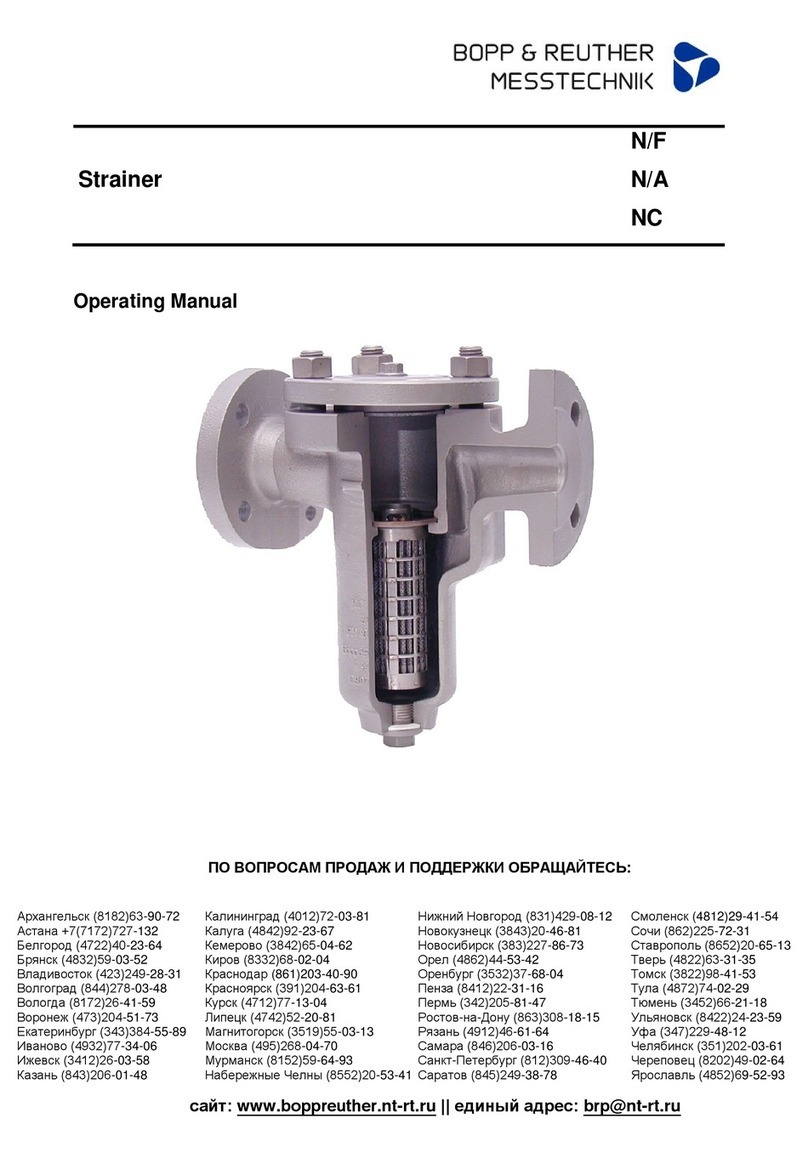
Bopp & Reuther
Bopp & Reuther N/F operating manual
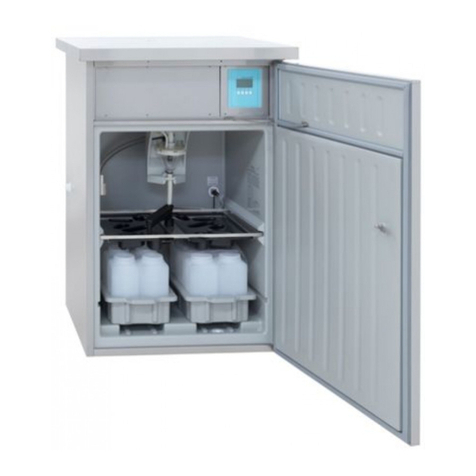
Endress+Hauser
Endress+Hauser ASP Station 2000 RPS20B operating instructions
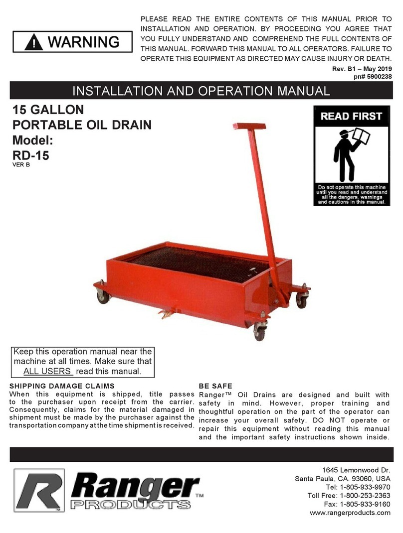
Ranger Products
Ranger Products RD-15 Installation and operation manual

Retrotec
Retrotec 450 Series quick guide

Siemens
Siemens ULTRAMAT 6 Series Compact operating instructions

Sure-Feed Engineering
Sure-Feed Engineering SE-900-EI Operations & parts manual

Autz + Herrmann
Autz + Herrmann ROTOCLEAR S operating manual
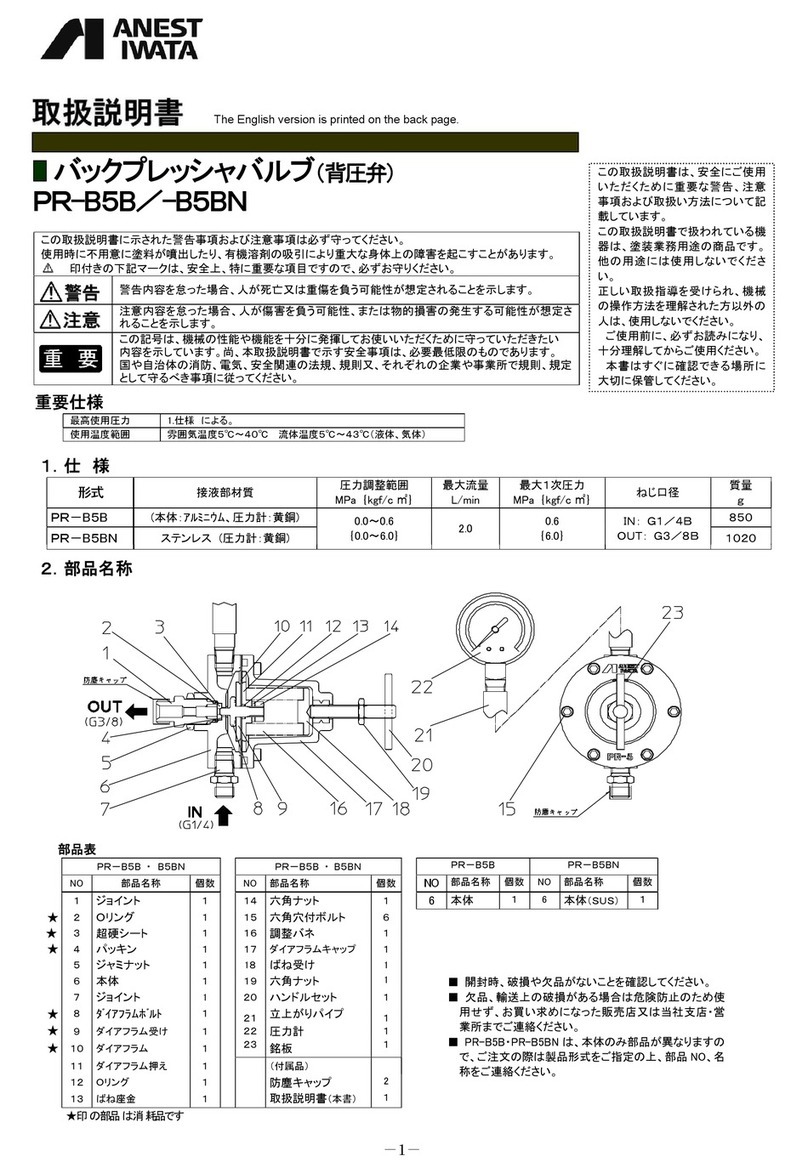
Anest Iwata
Anest Iwata PR-B5B instruction manual
Edge Technologies
Edge Technologies V-65 Series Operation manual
Tormach
Tormach 33318 Technical document


