CornellCookson SGH Series User manual

INSTALLATION INSTRUCTIONS
AND
OPERATION MANUAL
SGH Series 380V/400V/415V
UL325-2010 Compliant
Commercial and Industrial Door Operator
Logic Control
Continuous Duty

SGH Series
380V/400V/415V
REVISION # 0003
DATE: 08/27/2021
1
CONTENTS
IMPORTANT INSTALLATION INSTRUCTIONS ................................................................................. 2
SPECIFICATIONS ............................................................................................................................... 3
TYPES AND SIZES OF DOORS ......................................................................................................... 4
INSTALLATION INSTRUCTIONS ....................................................................................................... 4
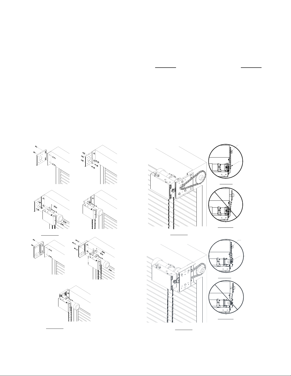
OPERATOR MOUNTING POSITIONS (for 1/2hp and 3/4hp) ....................................................... 4
OPERATOR MOUNTING POSITIONS (for 1hp, 1½hp and 2hp) .................................................. 4
OPERATOR MOUNTING ............................................................................................................. 5
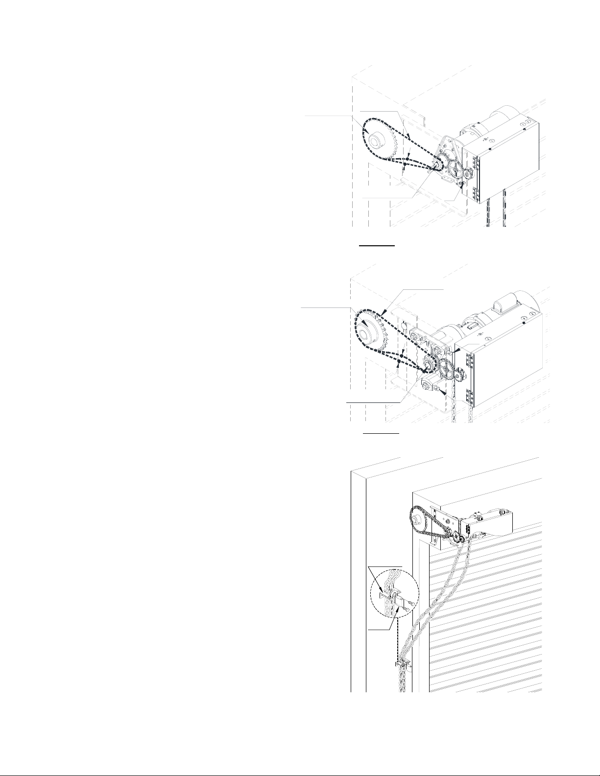
DRIVE CHAIN ADJUSTMENT ...................................................................................................... 6
HAND CHAIN ADJUSTMENT ....................................................................................................... 6
WIRING INSTRUCTIONS .................................................................................................................... 7
CONTROL WIRING ...................................................................................................................... 8
ENTRAPMENT DEVICES WIRING .............................................................................................. 9
INPUT POWER CONNECTIONS ...................................................................................................... 10
LIMIT SWITCH ADJUSTMENT ......................................................................................................... 11
CONTROL SETTINGS ...................................................................................................................... 12
CONTROL FUNCTION ............................................................................................................... 12
AUXILIARY FUNCTION .............................................................................................................. 13
TIMER INSTRUCTION ............................................................................................................... 14
LCD DISPLAY INSTRUCTION ................................................................................................... 16
LIGHT INDICATION .......................................................................................................................... 17
WIRING DIAGRAMS ......................................................................................................................... 18
TERMINAL CONNECTIONS ...................................................................................................... 22
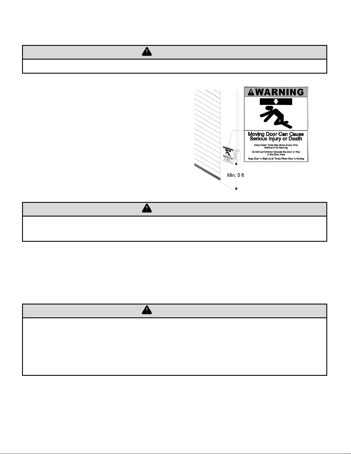
IMPORTANT SAFETY INSTRUCTIONS ........................................................................................... 23
TESTING ........................................................................................................................................... 24
PUSH BUTTON STATION TESTING ......................................................................................... 24
EMERGENCY MANUAL OPERATION ....................................................................................... 24
MAINTENANCE INSTRUCTIONS ..................................................................................................... 25
APPENDIX 1: Multiple Sensing Devices Connection Instruction ................................................. 26
APPENDIX 2: Control Connections Diagrams ............................................................................... 27
APPENDIX 3: Control Connections Diagrams ............................................................................... 28

SGH Series
380V/400V/415V
REVISION # 0003
DATE: 08/27/2021
2
IMPORTANT INSTALLATION INSTRUCTIONS
WARNING – To reduce the risk of death or serious injury to
persons:
1. READ AND FOLLOW ALL INSTALLATION INSTRUCTIONS.
2. Install only on a properly operating and balanced door. A door that is operating improperly could
cause severe injury. Have qualified service personnel make repairs to cables, spring assemblies,
and other hardware before installing the operator.
3. Remove all pull ropes and remove, or make inoperative, all locks (unless mechanically and/or
electrically interlocked to the power unit) that are connected to the door before installing the
operator.
4. Install the door operator at least 8 feet or more above the floor if the operator has exposed moving
parts. If the operator must be mounted less 8 ft (2.44 m) above the floor, then exposed moving parts
must be protected by covers or guarding. Contact the manufacturer.
5. Do not connect the door operator to the source of power until instructed to do so.
6. Locate the control station: (a) within sight of the door, and (b) at a minimum height of 5 feet above
floors, landings, steps, or any other adjacent walking surface and (c) away from all moving parts of
the door.
7. Install the Entrapment Warning Placard next to the control station in a prominent location.
8. Make sure the available power supply to be connected to the operator is of the same voltage,
frequency, phase and wattage as indicated on the nameplate of the operator.
9. Read and understand the wiring diagram of the operator and the control station (open-close-stop
push button), and any other equipment to be connected to the operator.
10. To avoid damage to the door and operator, make all door locks inoperative. Secure locks in the
unlocked position, or install external electrical interlocks to prevent operation with the locks
engaged.
11. Always disconnect power whenever installing or servicing the door operator or door.
12. All wiring must be permanent and comply with National Electrical Code (NEC) and local code
requirements.
13. Any change in mounting position may result in a change of operator rotation and consequently in a
change of control functions. Consult factory for any changes.
14. If the operator is provided with an auxiliary chain operator, the hand chain must be kept inside the
chain bag when operating electrically.
15. For products having a manual release, instruct the end user on the operation of the manual release.

SGH Series
380V/400V/415V
REVISION # 0003
DATE: 08/27/2021
3
SPECIFICATIONS
MOTOR
Duty Cycle: Continuous duty
Horsepower: 1/2 hp, 3/4 hp, 1 hp, 1½ hp, 2 hp
Speed: 50Hz – 1400 RPM, 60Hz – 1700 RPM
Voltage: 380V/400V/415V – 3 phase
Current: See motor nameplate
ELECTRICAL
Transformer: 24VAC
Wiring Type: Momentary pressure open, stop, constant pressure close
(
provided standard
)
, with provision for momentar
y
pressure close*
Limit Adjustment: Linear driven, fully adjustable screw type cams.
MECHANICAL
Drive Reduction: 43:1 (1/2 & 3/4 hp), 57:1 (1 & 1½ hp), 82:1 (2 hp)
Output Shaft Speed: 50Hz - 32 RPM (1/2 & 3/4 hp), 25 RPM (1 & 1½ hp), 17 RPM (2 hp)
60Hz - 39 RPM (1/2 & 3/4 hp), 30 RPM (1 & 1½ hp), 21 RPM (2 hp)
Door Speed: 6 - 8” per sec. average (typical)
Brake: Solenoid actuated brake
Emergency Chain Hoist: Standard
ENTRAPMENT PROTECTION
Sensing Edge*: (Optional) Sensing device attached to the bottom edge of the door.
Non-Contact Device*: (Optional) Photo eye device.
* Per the requirements of UL Standard 325, the door operator is setup for constant pressure
to close the door. As an alternative, the door may be provided with a monitored entrapment
protection device that will reverse the door upon contact with or detection of an obstruction
during closing. Adding an entrapment device would enable momentary close operation.
*Note:
1. Non-contact device (photo eye) can be used on doors up to 45 ft. wide (or maximum rated range of
device if less than 45 ft.). Use a sensing edge to provide entrapment protection on doors over 45 ft.
wide.
2. Sensing edge can be used on all doors.

SGH Series
380V/400V/415V
REVISION # 0003
DATE: 08/27/2021
4
TYPES AND SIZES OF DOORS
Consult factory for details.
INSTALLATION INSTRUCTIONS
OPERATOR MOUNTING POSITIONS (for 1/2hp and 3/4hp)
NOTE: Any change in mounting position
may result in a change of operator rotation
and consequently in a change of control
functions. Consult factory for any changes.
(LH=LS and RA, RH=RS and LA)
Operators mounted in alternate positions
(LA, RA) require the long mounting legs in
lieu of the standard short mounting legs.
Consult factory for changes in
mounting positions.
RS RA
LS LA
OPERATOR MOUNTING POSITIONS (for 1hp, 1½hp and 2hp)
NOTE: Any change in mounting position
may result in a change of operator rotation
and consequently in a change of control
functions. Consult factory for any
changes. (LH=LS and RA, RH=RS and LA)
Operators mounted in alternate positions
(LA, RA) require a straight mounting plate
in lieu of the standard bent plate.
Consult factory for changes in
mounting positions.
RS
LS
RA
LA

SGH Series
380V/400V/415V
REVISION # 0003
DATE: 08/27/2021
5
OPERATOR MOUNTING
1. Before the operator is installed, verify that
the door is properly operating and
balanced.
2. Make sure the layout of the mounting
holes on the bracket is correct.
3. Bolt the operator mounting plate to the
door bracket plate.
4. Attach and tighten the three mounting legs
to the mounting plate. (Not applicable for
1hp, 1½hp, 2hp)
5. Mount the operator to the three legs and
tighten (for 1/2 and 3/4hp only). For other
horsepowers, mount the operator to the
mounting plate.
(Figure 1 - for 1/2hp and 3/4hp)
(Figure 2 - for 1hp and 1½hp)
6. When the operator assembly is attached to the door
bracket, be sure the door driven sprocket is
properly aligned with the operator drive sprocket
before securing the driven sprocket to the shaft.
(See Figure 3 for 1/2hp and 3/4hp; see Figure 4 for
1hp and 1½hp)
7. The shelf or bracket must provide adequate support
for the operator. Prevent play between the
operator and the door shaft. The operator must be
securely attached with the drive shaft parallel to the
door shaft. It may be necessary to field brace the
operator/bracket.
Door
Sprocket
Operator
Drive
Sprocket
Correct
Incorrect
(Figure 3 - for 1/2hp and 3/4hp)
Correct
Incorrect
Door
Sprocket
Operator
Drive
Sprocket
(Figure 4 - for 1hp and 1½hp)

SGH Series
380V/400V/415V
REVISION # 0003
DATE: 08/27/2021
6
DRIVE CHAIN ADJUSTMENT
NOTE: Use correct type, size and proper
length of roller chain.
1. Adjust the drive chain by tilting or move the
operator so that there is about 1/4” of slack
when the chain is depressed.
Note: The set screw included in the operator
may be used for adjustment.
(See figure 1- S1 location for 1/2hp and
3/4hp), (See figure 2 - T1, T2 for 1hp and
1½hp).
2. Once the drive chain has been tightened and
the base leg screws have been set, then
tighten the operator set screws.
Drive Chain
Door Sprocket
Drive Sprocket
1/4"
S1
(Figure 1 - for 1/2hp and 3/4hp)
Drive Chain
Door Sprocket
Drive Sprocket
T2
1/4"
T1
(
Fi
g
ure 2 - for 1hp and 1½hp
)
HAND CHAIN ADJUSTMENT
Cut and reconnect chain with different color link
provided.
Chain Holder
Optional

SGH Series
380V/400V/415V
REVISION # 0003
DATE: 08/27/2021
7
WIRING INSTRUCTIONS
WARNING
Disconnect power at the fuse box before proceeding with any wiring.
1. Do not install any wiring or attempt to run this operator without checking the wiring diagram located
on the inside of the control box cover.
2. Do not turn on power until you have finished making all power and control wiring connections.
3. Do not run power and control wiring in the same conduit.
4. Any wire connected to the control panel must be protected by conduit or other means to ensure the
safety and permanency of the wiring.
5. Use copper wire inside the control panel.
6. A separate circuit of adequate capacity is needed for the operator.
7. The operator must be properly grounded. The ground screw, painted green, is located inside the
control panel.
8. For an operator, system, or external device requiring field installed wiring between a Class 2 output
of an operator and an external device, the type of wiring shall be R/C (AVLV2/8), AWM, min. 22
AWG, rated 60°C, with VW-1/FT2.
WARNING
Failure to properly ground the operator could result in electric shock and serious injury
or death.
To avoid damage to door and operator, make all door locks inoperative. Secure lock(s)
in the unlocked position, or install electrical interlocks to prevent operation with the
lock engaged.

SGH Series
380V/400V/415V
REVISION # 0003
DATE: 08/27/2021
8
CONTROL WIRING
WARNING
Disconnect power at the fuse box before proceeding with any wiring.
1. Locate the control station where the user can
clearly see the operation of the door. Mount the
enclosed placard adjacent or near the door.
WARNING
Controls shall be located far enough away from the door, or positioned such that the user is
prevented from coming in contact with the door, while operating the controls.
2. Do not run control wiring in the same conduit as power wiring.
3. Any wire connected to the control panel must be protected by conduit or other means to ensure the
safety and permanency of the wiring.
WARNING
Do not use radio controls with your operator unless some type of entrapment
protection device has been installed. Failure to do so may result in serious injury or
death to person(s) trapped beneath the door.
Changing from left hand to right hand or vice versa could result in change of control
wiring. Consult factory for details.

SGH Series
380V/400V/415V
REVISION # 0003
DATE: 08/27/2021
9
ENTRAPMENT DEVICES WIRING
WARNING
If the door is not visible from the control station, or if any device other than the control
station is used to activate the door, an entrapment protection device must be installed on
the door. Failure to install an entrapment protection device may result in serious injury or
death to person(s) trapped beneath the door.
1. Complete limit switch adjustments before
making any sensing edge/non-contact
device wiring connections to the operator.
Sensing Edge
Photo Eye
6" max. above floor
Entrapment Device Options:
Sensing Module Device Manufacturer Model
ELR
2-wire resistive sensing
edge
Miller Edge Inc.
* End of Line resistor type
edge must have model
number with Suffix T2.
ME110*, ME111*, ME120*, ME123*, ME112*,
ME113*, ME116*, ME117*
MT21*, MU21*, MT22*, MU22*, MC22*, MU33*,
MC271*, CPT223*
MEL-TXYY, MEL-RXYY
RB-G-K10
ASO GE225, GE125, GE245, GE F45, GE F50, GE F56,
GE F65, GE F85, GE F115
IR
Monitored photo eye
FRABA Inc.
Optical Edge Sensors and Photo Eyes, Models
OPTOEDGE, OPTOEYE, OSE, OPE, OSE-P,
OSE-R, OSE-T, RAY-N
Reflective Photo E
y
e, Models Ra
y
/RT -1004, -2004
Martec Access Products Inc. 1266
Miller Edge Inc. IG2, MIRM
RB-D-K10
Note: Please refer to sensing device manufacturer for specific installation and maintenance requirements.
2. After installation, be sure that the operator, controls, and sensing edge or other entrapment
protection devices have been tested and function properly.

SGH Series
380V/400V/415V
REVISION # 0003
DATE: 08/27/2021
10
INPUT POWER CONNECTIONS
123478910
2324P5P6E5E6
L1L2L3
L1L2L3
Three-phase power source
See operator plate for
correct voltage.

SGH Series
380V/400V/415V
REVISION # 0003
DATE: 08/27/2021
11
LIMIT SWITCH ADJUSTMENT
Make sure the limit cams are positioned between the limit switch actuators before proceeding
with adjustments.
1. Open / Remove the control panel cover.
2. Open or close door to determine the moving direction of the limit switch cams.
3. Open or close door to the desired position.
WARNING
Disconnect power before adjusting limit switch cams.
4. While pressing the spring-loaded lever (G), which holds the limit switch cams in place, adjust the limit
switch cam (E or F) until the micro switch (C or D) clicking sound is heard.
5. If the limit switch cam cannot be rotated to its desired position, release the lever and move the door
away from the desired position, then adjust the limit switch cam to its desired position. It may be
necessary to repeat this step until the exact position has been reached.
6. Repeat step 3 and 4 for the opposite position. Adjust close limit cams so that actuator is engaged as
door fully seats at the floor.
7. Micro switch (A or B) can be adjusted to accommodate sensing edge cut-off position.
A
D
B
C
F
G
E
NOTE: “C” is usually the open limit switch and “D” is usually the close limit switch.

SGH Series
380V/400V/415V
REVISION # 0003
DATE: 08/27/2021
12
CONTROL SETTINGS
CONTROL FUNCTION
ON
OFF
Timer
TIMER
M.OP
ON
OFF
M.CL
E.OP
ON: Momentary Pressure
OFF: Constant Pressure
Open
Close
ON
OFF
Auto Open
Safety Switch
ON
OFF
ON
OFF
ON
OFF
1
A. A-2.
23478910
2324P5P6E5E6
L1L2
1.Stop
2.Open
3.Close
4.Com
7&8 Close
Warning
signal
24VDC
A-1.
1234789102324P5P6E5E6
IR: P5&P6 ELR:E5&E6
(ELR-End of line resistor).
ON: Momentary Pressure
OFF: Constant Pressure
9&10
External nterlock
23&24
Timer Defeat
S10S12S11S13
L3

SGH Series
380V/400V/415V
REVISION # 0003
DATE: 08/27/2021
13
AUXILIARY FUNCTION
Open door
Stop door
Close door
Radio control
B-1.
B-2.
4 3 2 1
1. 1&2 Open limit dry contact
2. 3&4 Close limit dry contact
2 12 1
CN12 CN13 CN14
SE
24VDC MAX 0.5A
+ -
Open door
Stop door
Close door
B-1.
B-2.
B-3.
SE
24VDC MAX 0.5A
+ -
R3 R2 R1
R1 R2 R3
24VAC
Push button
24VAC
B.B.

SGH Series
380V/400V/415V
REVISION # 0003
DATE: 08/27/2021
14
TIMER INSTRUCTION
Note: To enable timer(s) –
1) Must switch Timer Switch S10 to ON. (See figure A-2 on Page 12 for location.)
2) Must remove jumper on Terminal PCB-CN2 (23,24). (See figure A-1 on Page 12 for location.)
C.
T1 T2 T3 + -
Timer 1 setup.
Down, decrease time.
Up, increase time.
C-2.
C-1.
Timer 2 setup.
Timer 3 setup.
Timer 3
Door Open Warning
dry contact
CN8
BUZZER
1. T1 – Mid-open timer : Timer starts counting when door leaves close limit. Door stops after
opening for set time. Pressing open again at mid-open position will cause door to open to
open limit.
T2 – Timer to close : Timer is active when door stops and is not at close limit.
T3 – Door Open Warning Timer : Timer is active when door leaves close limit.
When time is up, contact will close. See figure C-1.
Terminals 23 and 24 external timer disable switch connection – jump to disable all timer
functions or install a switch between 23 and 24. When the switch on 23, 24 is open and S10
switch is ON, all timers are enabled. When the switch on 23, 24 is closed or S10 switch is OFF,
all timers are disabled.

SGH Series
380V/400V/415V
REVISION # 0003
DATE: 08/27/2021
15
2. To Set Timer 1 (Mid-open Timer)
Remove jumper from terminal (23,24)
to enable Timers.
Turn timer switch S10 to ON.
Press
T1
and hold for 5 seconds.
Display will flash.
Use
+
and
-
to increase or to
decrease time.
Press
T1
to save setting. Without
pressing, no adjustment is saved.
+
T1 T2
Min. 1 Sec
Set the
desired time .
Max. 99 Sec
T1 T2
Mid-Open Timer
Max. 99 Sec
+-
+-
Min. 1 Sec
T1
T1
T1
T3
T3
T1
T1
T1 T2 T3 -
3. To Set Timer 2 (Timer to close)
Remove jumper from terminal (23,24)
to enable Timers.
Turn timer switch S10 to ON.
Switch M.CL switch to ON. (See
figure A-2 on Page 12 for location.)
Press
T2
and hold for 5 seconds.
Display will flash.
Use
+
and
-
to increase or to
decrease time.
Press
T2
to save setting. Without
pressin
g
, no ad
j
ustment is saved.
Min. 1 Sec
T2
Min. 1 Sec
Set the
desired time .
T1 T2
T1 T2
Reclose Timer
T2
T2
T2
T2
T2
Max. 99 min 59 Sec
Max. 99 min 59 Sec
+-
T3
T1 T2 +-
T3
+
T3 -
4. To Set Timer 3 (Buzzer Timer)
Remove jumper from terminal (23,24)
to enable Timers.
Turn timer switch S10 to ON.
Press
T3
and hold for 5 seconds.
Display will flash.
Use
+
and
-
to increase or to
decrease time.
Press
T3
to save setting. Without
pressing, no adjustment is saved. Min. 1 Sec
Min. 1 Sec
Set the
desired time .
T1 T2
T1 T2
Door Open Warning Timer
T3
Max. 99 min 59 Sec
Max. 99 min 59 Sec
+-
T3
T1 T2 +-
T3
+
T3 -
T3
T3
T3
T3
T3

SGH Series
380V/400V/415V
REVISION # 0003
DATE: 08/27/2021
16
5. To confirm timer value
Set Mode Set Mode
Set Mode
Select Time r
T1
T2
T3
T1 T2 +-
T3
T1 T2 +-
T3 T1 T2 +-
T3
T1 T2 +-
T3
Note: To enable timer(s) –
1) Must switch Timer Switch S10 to ON. (See figure A-2 on Page 12 for location.)
2) Must remove jumper on Terminal PCB-CN2 (23,24). (See figure A-1 on Page 12 for location.)
LCD DISPLAY INSTRUCTION
Display Status Display Status
T1
T1 setting
T1 or T2 or T3
setting completed
T2
T2 setting
Door closing
T3
T3 setting
Door opening

SGH Series
380V/400V/415V
REVISION # 0003
DATE: 08/27/2021
17
LIGHT INDICATION
5
4
3
8
9
18
16
17
LED16 STOP Control station stop
ON: Connect with 3 button
control station and not
activate STOP button.
OFF: Not connect with 3
button control station
or activate STOP
button.
LED3 OLS Door open limit
ON: Door at open limit.
OFF: Not at open limit.
LED5 CLS Door close limit
ON: Door at close limit.
OFF: Not at close limit.
LED4 SLS AUX close Limit contact
ON: Door at AUX close limit.
OFF: Not at AUX close limit.
LED17 OPEN Open button
ON: Activated.
OFF: Not activated.
LED18 CLOSE Close button
ON: Activated.
OFF: Not activated.
C.L.S.
LED30
VVS
SAFE
CLOSE
S.L.S.
STOP
OPEN
DEVICE
O.L.S.
LED9 SAFE Sensing device
ON: Sensing device circuit activated.
OFF: Sensing device circuit ok or not
activated.
LED8 DEVICE Device light
ON: When the sensing device connected
on terminal CN2 (E5,E6/P5,P6) is
normal.
OFF: Sensing device disconnected, failed
or damaged.

SGH Series
380V/400V/415V
REVISION # 0003
DATE: 08/27/2021
18
WIRING DIAGRAMS
4
123
R
BK
WH
GR
STOPCLOSEOPEN
INPUTPOWER
380V/400V
3PHASE

SGH Series
380V/400V/415V
REVISION # 0003
DATE: 08/27/2021
19
4
12
3
R
BK
WH
GR
STOP CLOSE OPEN
INPUTPOWER
380V/400V
3PHASE
Other manuals for SGH Series
1
Table of contents
Other CornellCookson Door Opening System manuals

CornellCookson
CornellCookson FS-500EP Series Troubleshooting guide

CornellCookson
CornellCookson FSNX-150EP Series Troubleshooting guide

CornellCookson
CornellCookson FS-150EP Series Troubleshooting guide

CornellCookson
CornellCookson SGH 50043E Troubleshooting guide

CornellCookson
CornellCookson SGHN4-300 E Series Troubleshooting guide

CornellCookson
CornellCookson SGH 30043E Troubleshooting guide

CornellCookson
CornellCookson SDCL-5045 Troubleshooting guide

CornellCookson
CornellCookson SGH 50023E Troubleshooting guide

CornellCookson
CornellCookson SGH Series Troubleshooting guide

CornellCookson
CornellCookson AlarmGard FST-EPBD Series Troubleshooting guide