8
Tweeter protection
Ci4 and Ci5 feature a tweeter protection circuit. If a microphone is used, or if the
speaker is used in environments with very high level of background sound, we recom-
mend turning on the protection circuit. For home installations, we recommend turning
off the protection.
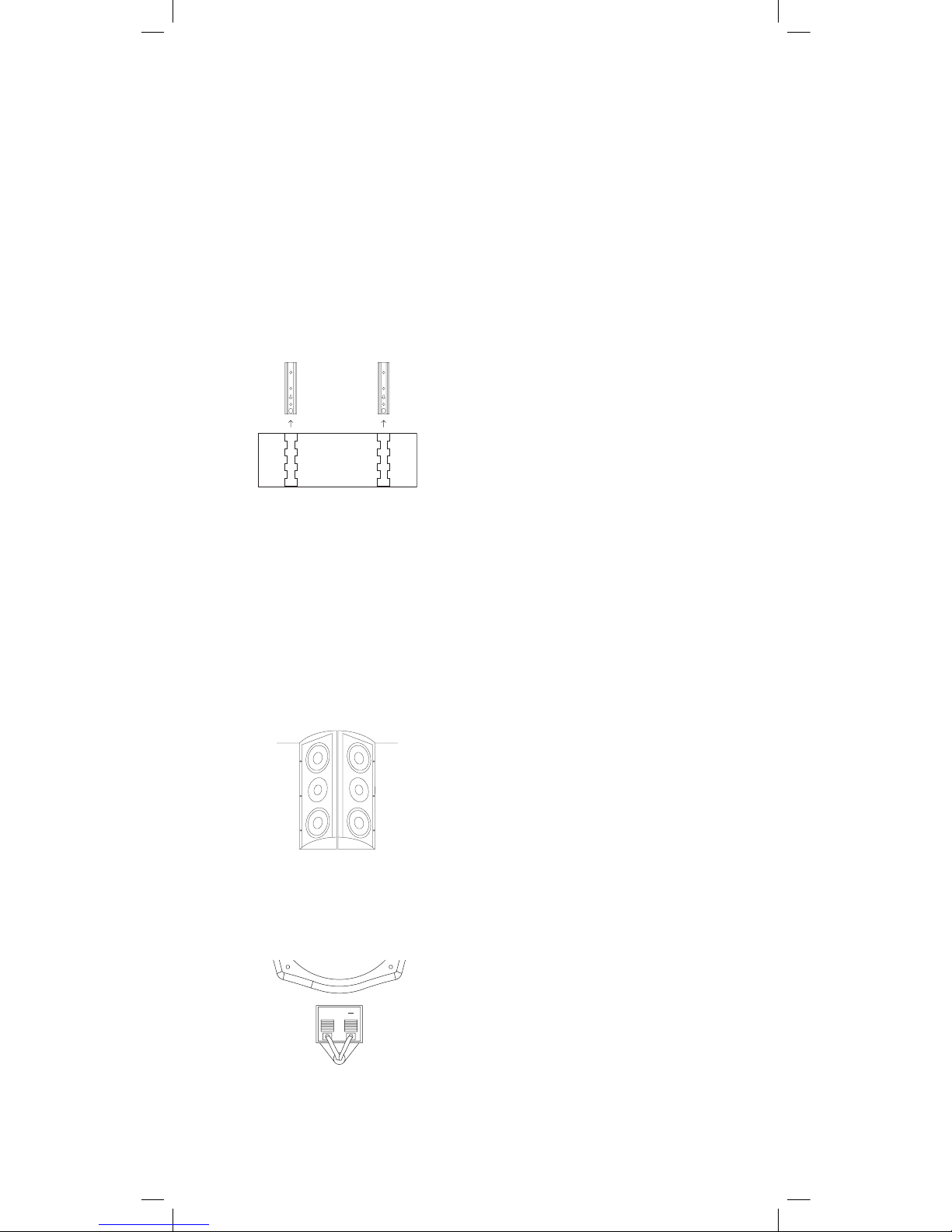
Outdoor mounting
The Ci series is IP54 rated, so they can be placed outside. If installed outdoors, the
insulation of the cabling should be resistant to water as well as the effects of tempera-
ture and ultraviolet radiation from the sun. Recommended insulations are: UV stabi-
lized polyethylene, neoprene, Teflon™, Silicon™, and Hypalon™. The following materials
are not recommended, because of potentially shorter life expectancy in outdoor en-
vironments: rubber, PVC (polyvinylchloride), polypropylene, polyurethane, and nylon.
UV-stabilized polypropylene may be acceptable.
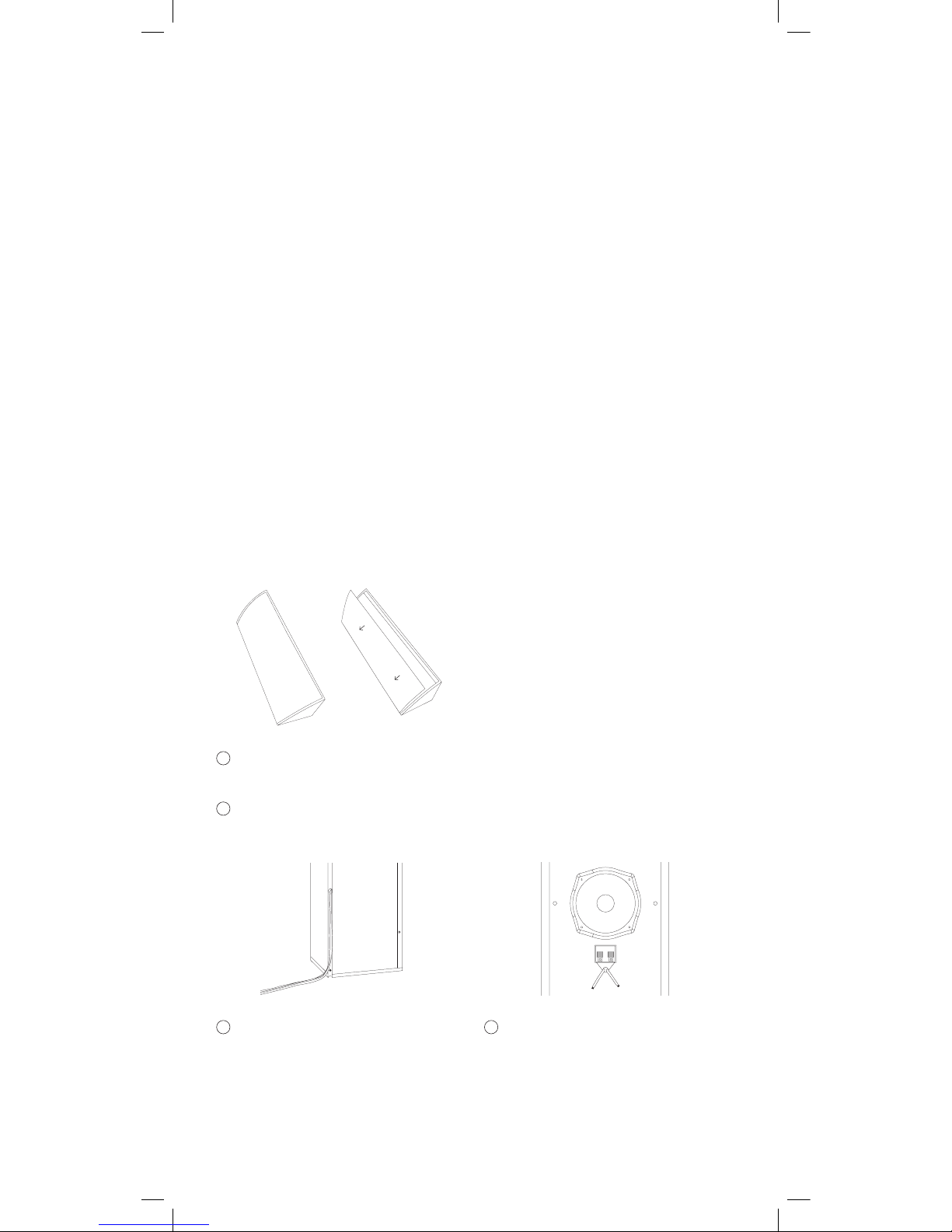
Safety wire
In installation terms, the CORNERED top-boxes are as much brackets as they are
speakers, because they mount flush to the walls and ceilings, so no safety wire is
needed (just like on traditional speaker installations, you don’t use a safety wire from
a bracket to the wall).
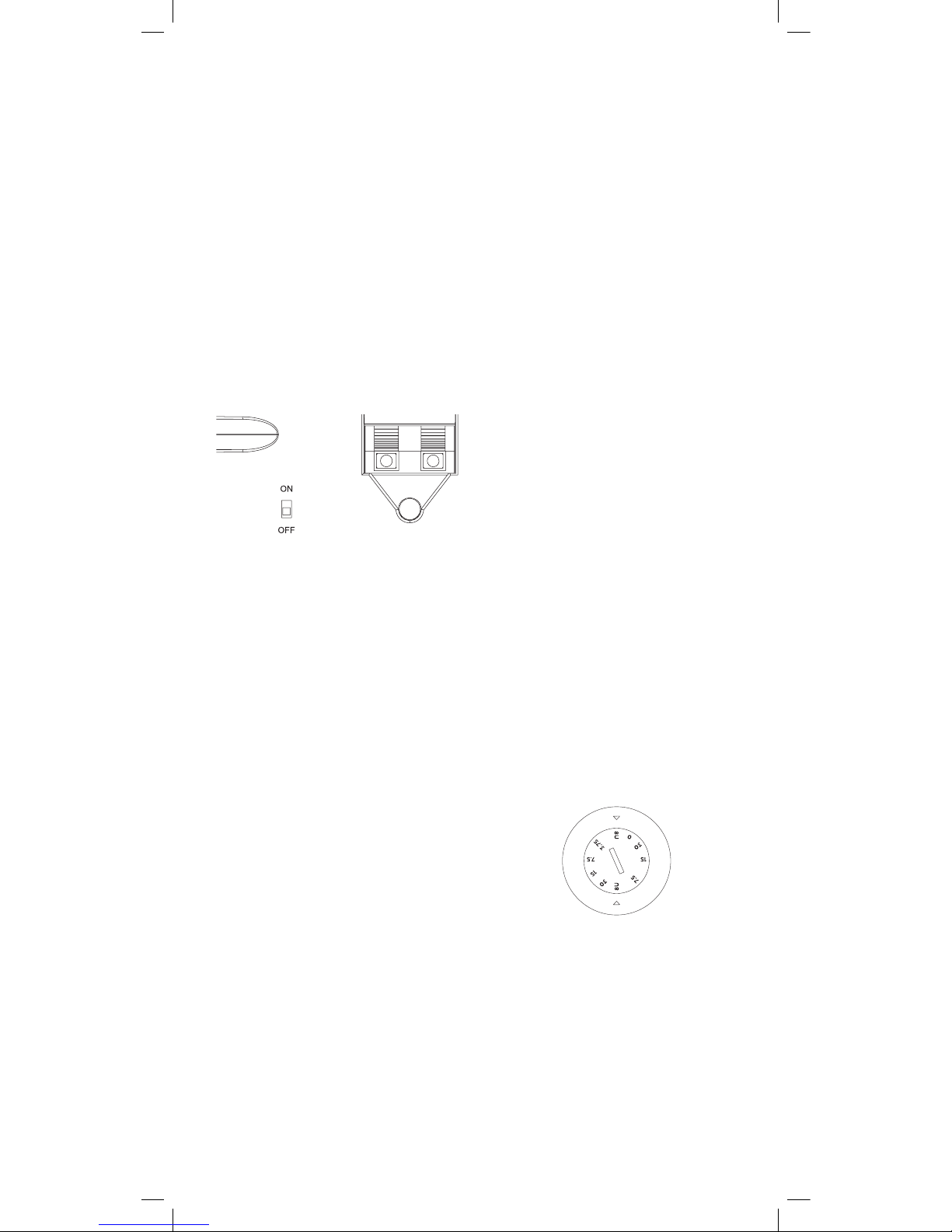
Operation
To enable, move the PTC switch to ON and to
disengage, move the switch to OFF.
Tweeter
Protection
70V
100V
Mode selection
Ci4-V & Ci5-V can be driven in 8 ohm or 70V
or 100V mode. The input tap selection switch
is placed behind the grille. On Ci4-V the taps
are 3,75, 7,5, and 15 watt output in 70V mode
and 7,5 and 15 watt output in 100V mode. On
Ci5-V the taps are 3,75, 7,5, 15 and 30 watt
output in 70V mode and 7,5, 15 and 30 watt
output in 100V mode. The rotary switch is
operated with a flat-head #7 screw driver.