01 t31 t2014
CORNEf [,4D'18 Eleclrosmog meler is designed for quick measurement of hlgh f requency (FF)
Electromagnelic wave field strength and power level for living environment, excellent for individual or company
with Electronragnetic wave safety concerns. lt has broad bandwidth (100MHz to BGHz), high sensitivily
(-55dBm to odBm) and fast response time. The MD18 has build-in 2.4GHz lrequency meter lo measure the
frequency of the delected RF signals and with internal sensing anlenna.
Applications:
- High lrequency (FF) Electromagnetic wave field strength and signal level measurement
- Mobile phone base station antenna radialion power density measurement
- Wireless communication applications (A[,4/FN/, TDL4A. GSlVl. DECT, CDMA, WiMax,3G,4G)
- RF power level measurement for transmitters, AC smart meter radiation from ulilities company
- Wireless LAN (Wi Fi. 2.4GHzl 5.8GHz), Bluetooth, Ultra wide-band detection, installation
- Spy camera, v/ireless bug finder
- Cellularcordless phone radiation safety level
- Microwave oven leakage delection
- Personal living environment EMF satety
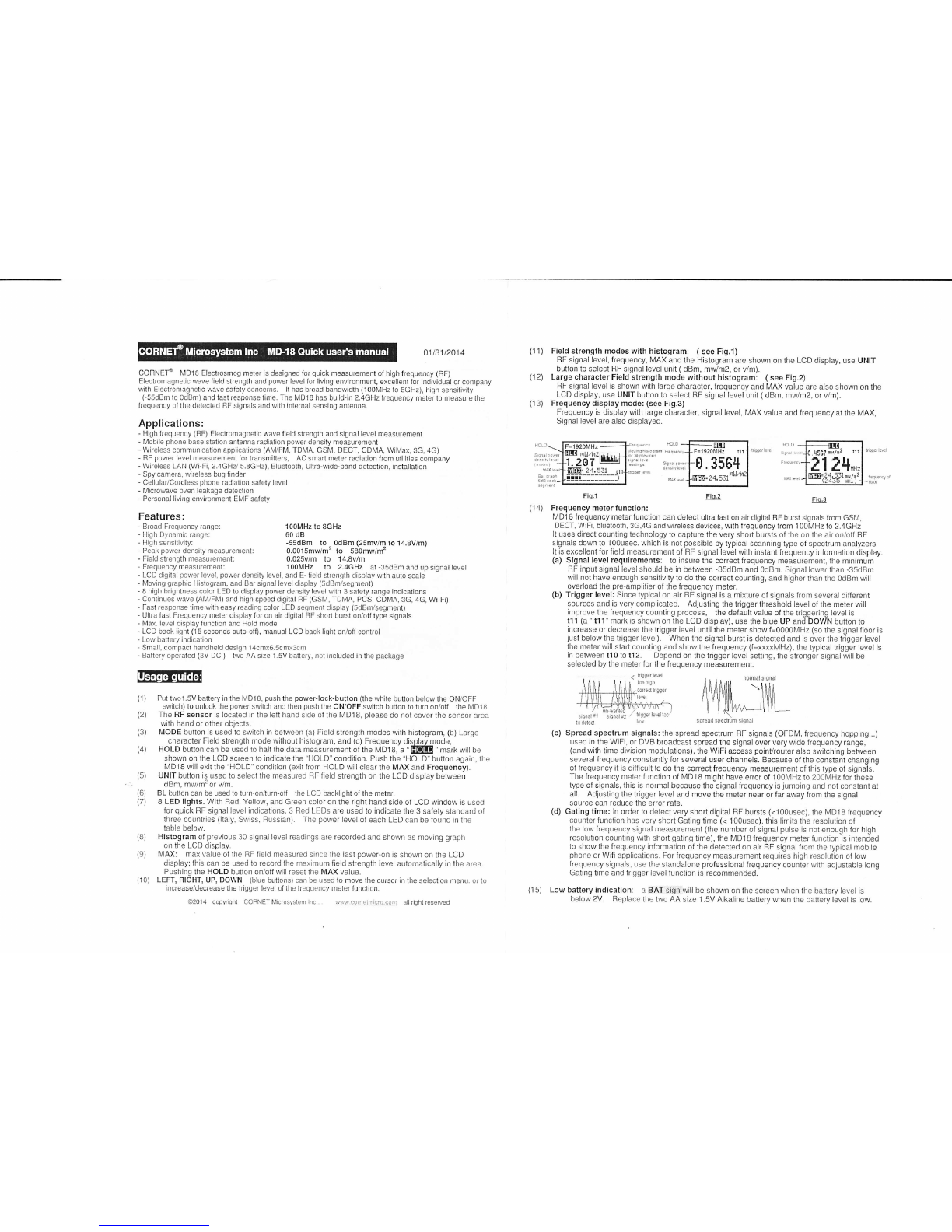
(1 1) Field slrength modes with histogram: ( see Fig.l)
RF signal level, frequency, MAX and the Histogram are shown on the LCD display, use UNIT
button to select RF signal level unit ( dBm, mw/m2, or v/m).
(12) Large characler Field strength mode without histogram: ( see Fig.2)
BF signal level is shown with large character, lrequency and MAX value are also shown on lhe
LCD display, use UNIT button to select RF signal level unit (dBm, mw/m2, or v/m).
(13) Frequency display mode: (see Fig.3)
Frequency is display with large character, signal level. MAX value and frequency al the N/AX,
Signal level are also displayed.
F=1920[4Hz tl1
0.3564
Features:
- Broad Frequency range:
- High Dynamic range:
- High sensitivity:
- Peak power density measurement:
- Field strength measurement:
- Frequency measurement:
'l00MHz to SGHz
60 dB
-55dBm to - odBm (25mv/m to 14.8V/m)
0.0015mw/m' to 580mw/m'
0.025v/m lo 14.8v/m
100MHz lo 2.4GHz at -35dBm and up signal level
Fio.l Fiq.2 Fio.3
(1 4) Frequency meter function:
MD18 f requency meter function can detect ultra fast on air digital RF burst signals from GSM,
DECT, WiFi, bluetooth, 3c,4c and wireless devices, with frequency lrom 100MHz lo 2.4GHz
It uses direct counting technology to capture the very short bursts of the on the air on/off RF
signals down to 1O0usec. which is not possible by typical scanning type of spectrum analyzers
It is excellent tor field measurement of RF signal level with instant frequency information display.
(a) Signal level requiremenls: to insure the correct frequency measurement, the minimum
FF input signal level should be in between -35dBm and OdBm. Signal lower than -35dBm
will not have enough sensjtivity to do the correct counting, and higher than the 0dBm will
overload the pre-amplifier of the frequency meter.
(b) Trigger level: Since typical or.r air RF signal is a mixture of signals from several different
sources and is very complicated, Adjusting the trigger threshold level of the rneter will
improve the frequency counting process, the default value of the triggering level is
t11 (a " t'11" mark is shown on the LCD display), use the blue UP and DOWN butron to
increase or decrease the irigger ievei unril the meier show f=0000N,4H2 (so the signal iioor is
just below the trigger level). When the signal burst is detected and is over the trigger level
the meter will start counting and show the lrequency (f=xxxxMHz). the typical trigger level is
in between t10 to t12. Depend on the trigger level setting, the stronger signal will be
selected by the meter for the frequency measurement.
Iri hi!i
ilrrEallrQ er
lrEl
Ufl
liqi3l;'1 siqnili: lr'lqir!!eilri
la delicl i:r
(c) Spread spectrum signals: the spread spectrum RF signals (OFDM. frequency hopping...)
used in lhe WiFi, or DVB broadcast spread the signal over very wide frequency range,
(and with time divjsion modulations), the WiFi access poinVrouter also switchinq between
several frequency constantly {or several user channels. Because o{ the constant changing
o{ frequency it is difficult to do the correct frequency measurement of this type of signals.
The frequency meter function of MD18 might have enor of 100MHz to 2001\,4H2 for these
type oi signals, this is normal because the signal frequency is jurnping and not constant al
all. Adjusting the trigger level and move the meter near or lar away from the signal
source can reduce the error rate.
(d) Gating time: ln order to detect very short digital RF bursts (<1 O0usec). the MDl B frequency
counter {unction has very short Gating time (< 100usec), this Iimits the resolution ot
the low frequency signal measurement (lhe number of signal pulse is not enough for high
resolution counting with short gating time), the MD18 frequency meter function is intended
to show the frequency information of the detected on air RF signal from the typical mobile
phone or Wifi applications. For frequency measuremenl requires high resokttion of low
frequency signals. use the standalone professional frequency counter wilh adjustabie Iong
Gating time and trigger level iunction is recommended.
(15) Low battery indication: a BAT sign will be shown on the screen when the battery level is
below 2V. Replace the two AA size 1.5V Alkaline baltery when the battery level is low.
- LCD digital power level. power density level, and E- field strenglh display with auto scale
- Moving graphic Histogram, and Bar signal level display (5dBnvsegment)
- 8 high brightness color LED to display power density level wlth 3 safety range indications
- Continues wave (AN,4/FN,4) and high speed digital RF (GSl\4, TDMA, PCS, CDN4A,3c, 4c, Wi-Fi)
- Fast response time with easy reading color LED segment display (sdBm/segment)
- Ultra iast Frequency meter display for on air digital RF short burst on/ofj type signals
- Max. level display lunclion and Hold mode
- LCD back light (15 seconds aulo-off), manual LCD back light on/off control
- Low batlery indication
- Small, compact handheld design 14cmx6.5cmx3cm
- Baltery operated (3V DC ) two AA size 1.5V battery, not included in the package
IfE;tltll:lmt!!
B
Put two1.5V battery in the [,4D18. push the powetrlock-bullon (the white button below the ON/OFF
switch) to unlock the power switch and then push the ON/OFF switch bulton to turn on/ofl the l\4D1 B.
The RF sensor is located in the leJt hand side of the l\,4D18. please do not cover the sensor area
with hand or other objects.
MODE button is used to switch in between (a) Field strength modes with histogram, (b) Large
character Field strength mode without histogram, and (c) Frequency display mode,
HOLD button can be used to halt the data measurement of the MD18, a " EBID " mark will be
shown on the LCD screen to indicate the "HOLD" condition. Push the "HOLD" button again, the
MD18 will exit the "HOLD ' condition (exit from HOLD will clear the MAX and Frequency).
UNIT button is used to select the measured FF field strength on the LCD display between
dBm, mw/m2 or v/m.
BL butlon can be used to turn on/turn-off the LCD backlight of the meter.
B LED lighls. With Red. Yellow, and Green color on the right hand side of LCD window is used
for quick RF signal level indications. 3 Fed LEDs are used to indicate the 3 safety standard of
three countries (ltaly, Swlss. Russian). The power level o{ each LED can be {ound in the
table below.
Histogram of previous 30 signal level readings are recorded and shown as moving graph
on the LCD display.
MAX: max value of the FF fjeld measured since the last power-on is shown on the LCD
display; this can be used to record the maximum field strength level automatically in the area
Pushing the HOLD button on/off wlll reset the MAX value.
LEFT, RIGHT, UP, DOWN (blue buttons) can be used to move the cursor in the selection menu. or to
increase,/decrease the trigger level of the frequency meter function.
(1)
(2)
(3)
(4)
(s)
(6)
(7)
(B)
(e)
(10)
O2014 copyrght CCFNET Microsystem lnc . !:i:...!:i,i2t:lit.ij.ij;:.::i jirt all right reserued