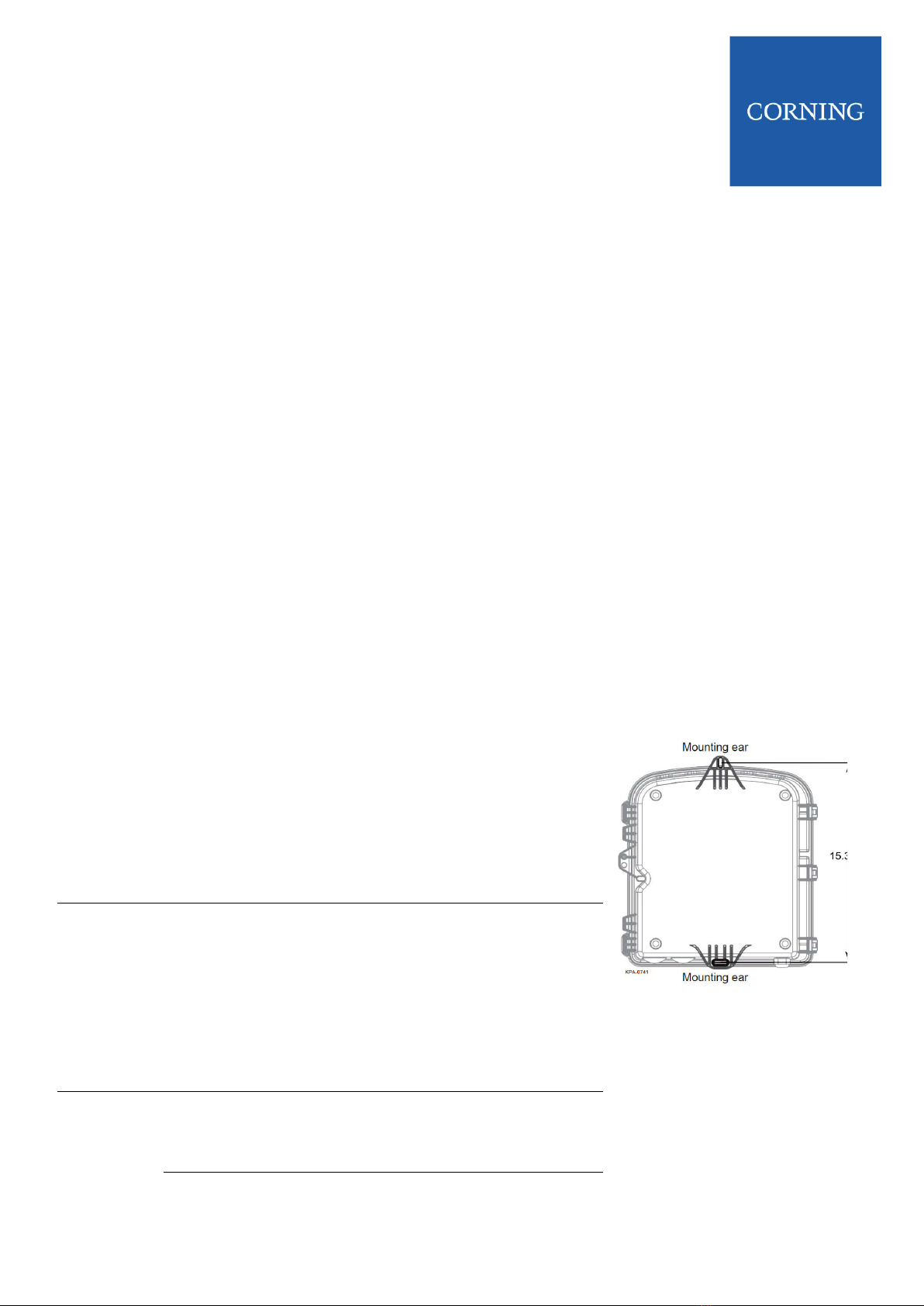
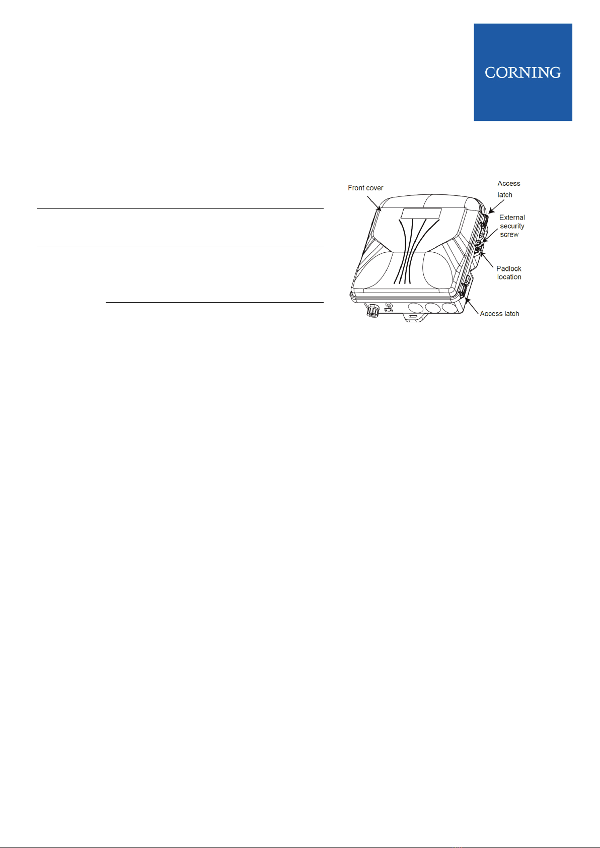
CORNING 1LAN-SPLT-132-486C User manual

ONE SD-LAN Wall
Mount Splitter Housing
(1LAN-SPLT-132-486C)
STANDARD RECOMMENDED PROCEDURE 000-000-AEN | ISSUE 1 | MARCH 2018 I Page 1
CMA-477-AEN
1 General |
Figure 1

ONE SD-LAN Wall
Mount Splitter Housing
(1LAN-SPLT-132-486C)
STANDARD RECOMMENDED PROCEDURE 000-000-AEN | ISSUE 1 | MARCH 2018 I Page 2
2 Carton Contents |
•Installation instruction
•Wall Mount Splitter housing
•Cable installation hardware
3 Tools and Materials Required |
3.1 Tools
•Can wrench
•Measuring tape
•Appropriate tool kit with fiber stripping tools
3.2 Materials
•Hardware for end-point cable installation
•Mounting hardware appropriate for the surface upon which the housing will be installed
4 Mounting the Housing |
Step 1
Select the appropriate location for the housing to be installed
according to your installation plan. Choose a vertical surface
near approved ground but away from downspouts,
permanent water sprinklers, or other water sources. Ensure
the housing is easily accessible from the front to allow
technicians to connect customers as they subscribe for
service.
Figure 2
Step 2
Using the housing as a template (Figure 2), ensure the unit is
square and mark the locations for the mounting hardware.
Install appropriate anchors (not provided) to the surface to
which the housing will be attached. Use shims (not provided)
on uneven surfaces to ensure the housing is square and to
prevent warpage. Place the unit on the mounting surface
over previously determined mounting location.
Step 3
Insert the mounting hardware through the mounting ears and
tighten securely to the mounting surface/wall before installing
cable into the cabinet.

ONE SD-LAN Wall
Mount Splitter Housing
(1LAN-SPLT-132-486C)
STANDARD RECOMMENDED PROCEDURE 000-000-AEN | ISSUE 1 | MARCH 2018 I Page 3
4.1 Wall Mounting PSU6 (Remote Power Option)
Step 1
Remove the rack-mounting brackets and set the
screws aside.
Figure 3 Dual Gang Box Mounting
Step 2
Using the four screws (previously set aside),
assemble the wall-mount brackets onto the sides
of the PSU6 so that the unit can be mounted
belly-to-wall. See Figure 3.
Notes: The unit should be mounted on the wall
with the DC connectors facing sidewards. See
Figure 5. Make sure that there is enough space
at the rear to insert/extract the PSMs.
Step 3
Using the wall-mount bracket keyholes as a
guide, mark the holes to be drilled on the wall.
Mount the PSU 7 inches horizontally from the
Wall Mount Splitter Housing. See Figure 4
Notes: This distance will affect the strip lengths
of the composite drop cables. If mounting is more
than 7 inches from splitter housing strip lengths
wil Need to be adjusted to allow for necessary
copper conductor length to reach PSU6 power
ports
Step 4
Insert appropriate bolts and mount unit.
Figure 4 Housing and PSU6 Wall Mounting

ONE SD-LAN Wall
Mount Splitter Housing
(1LAN-SPLT-132-486C)
STANDARD RECOMMENDED PROCEDURE 000-000-AEN | ISSUE 1 | MARCH 2018 I Page 4
5 Accessing the Housing |
Step 1
Use a 3/8-in can wrench to loosen the
security screw on the front cover.
Figure 5 ONT Fiber Port
Step 2
Depress the access latches on the side of the
unit and open the front cover (Figure 5).
Step 3
Open the interior security door inside the
cabinet with the can wrench to access the
bottom chamber.

ONE SD-LAN Wall
Mount Splitter Housing
(1LAN-SPLT-132-486C)
STANDARD RECOMMENDED PROCEDURE 000-000-AEN | ISSUE 1 | MARCH 2018 I Page 5
6 Installing Feeder Cable|
Step 1
Remove the hole plug for the feeder entry port. Install an appropriate size fitting and conduit (if
conduit is used) per standard local practices and ensure proper sealing. Feed the end-point cables
into the housing through the fitting.
Figure 6
Step 2
Strip 65 inches of the feeder cable jacket with proper cable entry tools
Step 3
Route one loop of the fiber around the radius guides in clockwise direction.
Step 4
Bring fibers to splitter pigtail connection in inside center of housing
Figure 7
Step 5
Terminate fiber and connect to splitter input adapter.
Step 6
Route and secure spare fibers so they will not be damaged.

ONE SD-LAN Wall
Mount Splitter Housing
(1LAN-SPLT-132-486C)
STANDARD RECOMMENDED PROCEDURE 000-000-AEN | ISSUE 1 | MARCH 2018 I Page 6
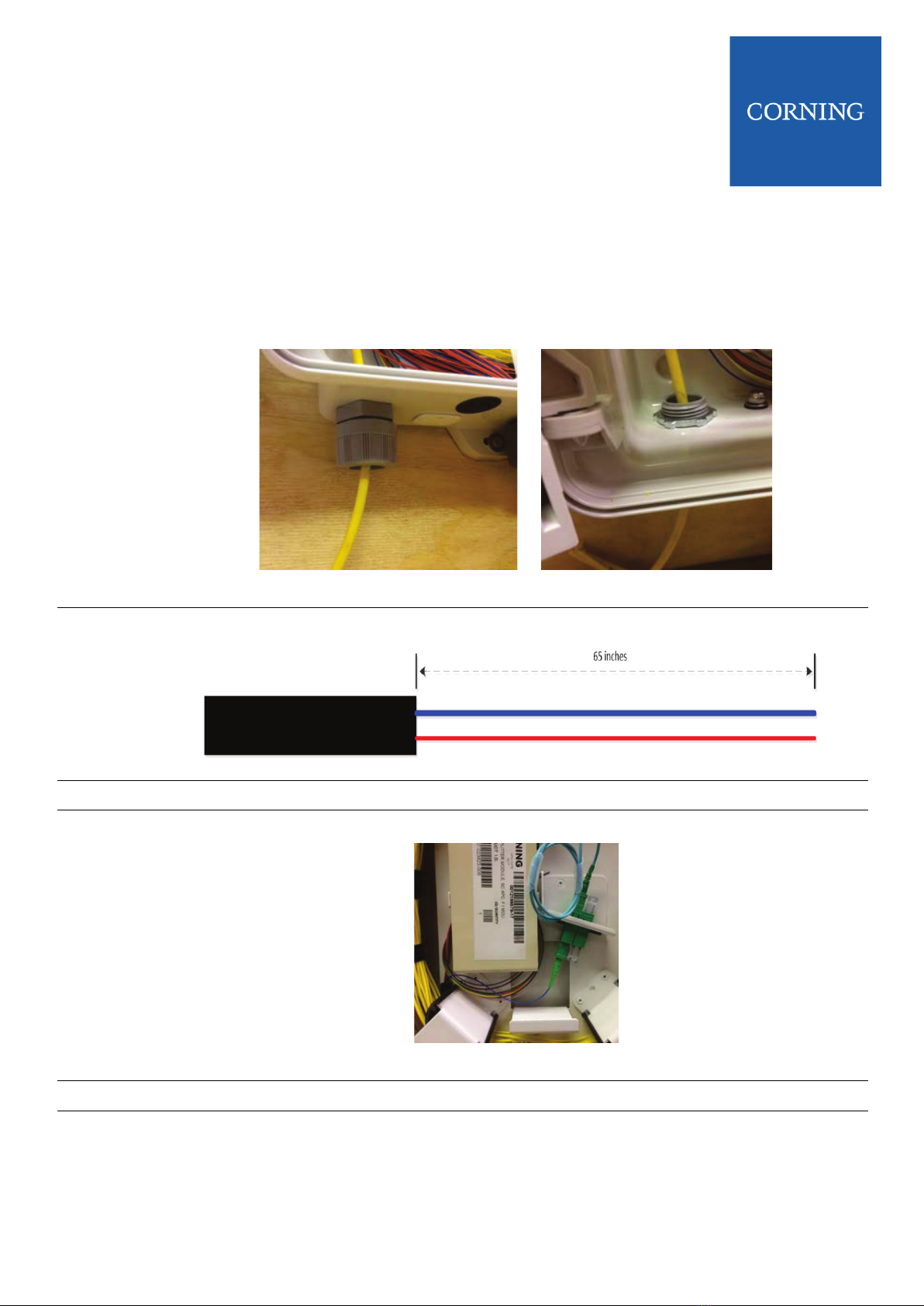
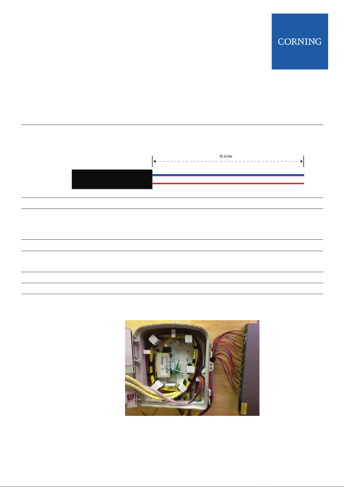
7 Installing End-Point Cable |
Spare end-point fiber connectors can be stored in a parking area on the front of the connector plate. Individual
connectors can be accessed as new subscribers are activated.
WARNING: Never look directly into the end of a fiber that may be carrying laser light.
Laser light can be invisible and can damage your eyes. Viewing it directly does not cause
pain. The iris of the eye will not close involuntarily as when viewing a bright light.
Consequently, serious damage to the retina of the eye is possible. Should accidental eye
exposure to laser light be suspected, arrange for an eye examination immediately.
WARNING: DO NOT use magnifiers in the presence of laser radiation. Diffused laser light
can cause eye damage if focused with optical instruments. Should accidental eye
exposure to laser light be suspected, arrange for an eye examination immediately.
CAUTION: Recommend the use of safety glasses (spectacles) conforming to ANSI Z87 for
eye protection from accidental injury when handling chemicals, cables, or working with
fiber. Pieces of glass fiber are very sharp and have the potential to damage the eye.
CAUTION: The wearing of cut-resistant safety gloves to protect your hands from
accidental injury when using sharp-bladed tools and armored cable is strongly
recommended. Use extreme care when working with severed armor. There will be a sharp
edge where armor is cut. To minimize the chance of injury from the cut armor, cover the
exposed edge with a wrap of electrical tape. To minimize the chance of injury from sharp-
bladed tools, always cut away from yourself and others. Dispose of used blades and armor
scrap properly.
CAUTION: Fiber optic cable is sensitive to excessive pulling, bending, and crushing
forces. Consult the cable specification sheet for the cable you are installing. Do not bend
the cable more sharply than the minimum recommended bend radius. Do not apply more
pulling force to the cable than specified. Do not crush the cable or allow it to kink. Doing so
may cause damage that can alter the transmission characteristics of the cable; the cable
may have to be replaced.

ONE SD-LAN Wall
Mount Splitter Housing
(1LAN-SPLT-132-486C)
STANDARD RECOMMENDED PROCEDURE 000-000-AEN | ISSUE 1 | MARCH 2018 I Page 7
Step 1
Remove one of the hole plugs from the bottom of the housing. Install an appropriate size fitting and
conduit (if conduit is used) per standard local practices and ensure proper sealing. Feed the end-
point cables into the bottom chamber through the fitting.
Step 2
Strip 95 inches of the end-point cable jacket from the cables with proper cable entry tools and
procedures exposing the fiber and copper conductors.
Step 3
Route one loop of fiber/copper around the radius guides in counter clockwise direction.
Step 4
Place spiral wrap around the bundle of fibers where they will transition from the bottom chamber to
the customer/drop adapter field. Secure spiral wrap to inner security door to prevent fiber from being
pinched when closing the door
Step 5
Route the fibers to the front of the housing, trimming lengths as needed and terminate fibers.
Step 6
Align the key on the connector with the key on the connector adapter. Install the connector into the
adapter. Park unused terminated fibers in the parking area.
Step 7
Route copper through one of the drop port holes out of the housing.
Step 8
Place spiral wrap around copper conductor bundles and secure.
Step 9
Route copper conductor bundle to PSU6 and terminate into power port connectors.
Note: See PSU6 Quick Start Guide
Figure 8

ONE SD-LAN Wall
Mount Splitter Housing
(1LAN-SPLT-132-486C)
STANDARD RECOMMENDED PROCEDURE 000-000-AEN | ISSUE 1 | MARCH 2018 I Page 9
Step 2
Remove the dust cap from the appropriate connector adapter. Clean each adapter before mating as
described in Section 9.
Step 3
Align the key on the connector with the key on the connector adapter. Install the connector into the
adapter.
Step 4
Record the connector terminations on the identification label inside the front cover (Figure 10) as
they are made.
Step 5
Close the front cover and secure it by tightening the external security screw with the can wrench
(approximately 15 in-lb torque).
9 Connecting End-Point Connectors after Initial Installation |
Step 1
Use a 3/8-in can wrench to loosen the external security screw and then depress the access latches
to open the door.
Step 2
Follow Steps 2 through 6 in Section 6 to connect end-points.
10 Connector Care and Cleaning |
WARNING: Isopropyl alcohol is flammable with a flashpoint at 54ºF. It can cause irritation
to eyes on contact. In case of contact, flush eyes with water for at least 15 minutes.
Inhalation of vapors irritates the respiratory tract. Exposure to high concentrations has a
narcotic effect, producing symptoms of dizziness, drowsiness, headache, staggering,
unconsciousness, and possibly death.
•Always keep dust caps on connectors and adapters when not in use.
•Ensure dust caps are clean before reuse.
•Use optical cleaning materials as standardized by your company.
•Clean the connector before every mating, especially for test equipment patch cords (jumpers).
•A minimum level of cleaning is listed below. Local procedures may require more rigorous cleaning methods.
Step 1
Remove plugs from the connector adapter.
Step 2
Wipe the connector ferrule twice with a lint-free wiping material moistened with isopropyl alcohol.
Then wipe across the end of the ferrule.
Step 3
Repeat previous step with a dry wipe.

ONE SD-LAN Wall
Mount Splitter Housing
(1LAN-SPLT-132-486C)
STANDARD RECOMMENDED PROCEDURE 000-000-AEN | ISSUE 1 | MARCH 2018 I Page 10
11 Testing |
11.1 Provisioning Tests |
Equipment should be tested from the source (or central office) to receiver at the time of provisioning to verify signal
continuity and acceptable loss limits. Use an optical power meter to verify signal continuity and determine whether
loss measurements are within specified local standards.
11.2 Troubleshooting Tests |
An optical power meter can be used to perform the first step in troubleshooting. A power meter designed for
measuring only dBm power levels is suitable for maintenance purposes.
For high attenuation:
•Remove connector and reclean connector and adapter.
•Verify cable ties are not too tight.
•Maintain appropriate fiber bend radius. Make sure there are no sharp bends.
Once a fault is isolated to the installed cable link, an optical time domain reflectometer (OTDR) is needed. An
OTDR can locate fiber events and measure the losses attributable to cable, connectors, splices, and/or other
components. The graphical display of loss over a cable’s entire length provides the most revealing analysis and
documentation available on a cable link, commonly referred to as its signature trace. Corning recommends
performing an OTDR analysis to document the integrity of the cable system, locate and measure each event or
component, and uncover faults throughout the cable. Follow the instructions provided with the OTDR tester you are
using.
12 Maintenance and Repair Procedures |
12.1 Maintain the Housing
No routine maintenance of this product is required to keep it in operational order. In the event of loss of service or
low performance, test the connections as described in Section 10. Reenter the bottom chamber, if necessary, to
determine which components are defective.
12.2 Reenter the Housing
Use a 3/8-in can wrench to loosen the external security screw and then depress the access latches to open the
front cover.
12.3 Replace Components
Contact Corning Engineering Services at 1-800-743-2671 for instructions to repair or replace broken or defective
components.
Table of contents
Other CORNING Media Converter manuals
Popular Media Converter manuals by other brands

Hagstrom
Hagstrom KE-XTUSB user manual

HSS Hire
HSS Hire 43416 Operating & safety guide

Comnet
Comnet CNMC2+1SFP Installation and operation manual

Cobalt Digital Inc
Cobalt Digital Inc 9927-2StoH product manual

YUAN High-Tech
YUAN High-Tech MULTI CONVERTER user manual

Pro-Ject Audio Systems
Pro-Ject Audio Systems DAC Box DS2 ultra Instructions for use