Corning Cable Systems Polska Sp. z o.o.
© Corning Cable Systems Polska Sp. z o.o.
Smolice 1E, 95-010 Stryków - Poland
Phone + 48-42 230 11 00 Fax: +48-42 230 11 01
Internet: www.corning.com/cablesystems
Printed in the Federal Republic of Germany on oxygen-bleached paper.
Subject to availability. Right of modication reserved.
Order No.: S46998-A6-P941
14.11. 2012
Disposal Note
Disposal of the products and their packaging must be carried out in strict compliance with the local laws currently in force.
Disclaimer
Corning Cable Systems Polska Sp. z o.o. accepts no liability for any damage arising from improper use of the product.
The extent of any liability in specic instances shall be limited to the General Terms and Conditions of Sale from Corning
Cable Systems Polska Sp. z o.o.
This product is state of the art.
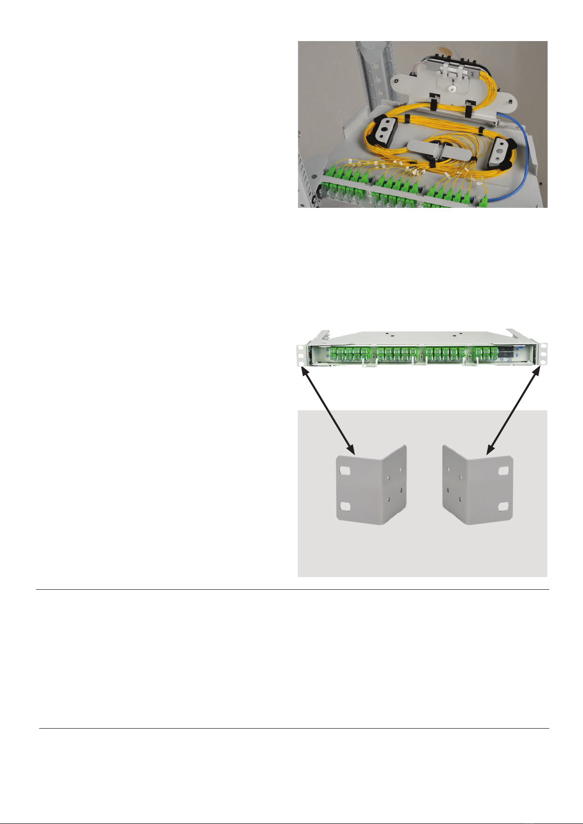
7. Installation in 21" frame.
To install subrack in 21" frame please exchange installed
brackets with 21" brackets on both sides (ordered
separately, check point 2.1).
Further installation steps are the same for both frames.
...and open cover with splice cassette.