Cosmo FLORENZ-T User manual

MONTAGE- UND BETRIEBSANLEITUNG
COSMO FLORENZ-T
DE
GB
FR
PL
RO

02
=
A
C
min. 304
157 960
III
Z
-40
=
157
A
B
CC
42
64 - 76
III
Detail Z
1
5
6
4
8
2
7 3
II
D
F
E
50 I
Abb. 1
Abb. 2
Abb. 3
D
GB
ACHTUNG !
Heizkörperrückansicht
ATTENTION !
Back of radiator
Heizkörperdimension,
Baulänge x Bauhöhe
Radiator Sizes,
total length x total height
[mm]
PTC-Elektro-
heizelement
PTC-Electrical
heating
[W] bei / at 60 °C
500 x 1194 600
500 x 1754 600
500 x 2154 900
600 x 1194 600
600 x 1754 900
600 x 2154 900
750 x 1194 600
750 x 1754 900
750 x 2154 900
900 x 1194 900
900 x 1754 900
900 x 2154 900
Baulänge / Total length
Bauhöhe / Total height
Entlüftung / Ventilation
Vorlauf / Flow pipe
Rücklauf / Return pipe

MONTAGE- UND BETRIEBSANLEITUNG 03
INSTALLATION/MONTAGE U. INBETRIEBNAHME
Die Installation und Inbetriebnahme Ihres Designheizkörpers COSMO FLORENZ-T ist von einer zugelassenen Fachfirma durchzuführen. Bei der Installation sind die
einschlägigen Normen bzw. die nationalen elektrotechnischen Sicherheitsvorschriften wie ÖVE- und VDE- Bestimmungen zu beachten.
Unter Berücksichtigung der geometrischen Maße des Designheizkörpers COSMO FLORENZ-T und der Anschlusselemente (Ventile, Verschraubungen) - siehe (Abb.1) - ist die Verroh-
rung vorzubereiten. Wird eine Elektoheizpatrone verwendet, kann diese in die 1/2“ Muffe I eingedichtet werden. Dabei sind die Hinweise der Elektropatronenmontagenanleitung zu
beachten. Die nicht verwendeten Anschlüsse mit den beigepackten Stopfen verschließen, wobei in eine der beiden Muffen lll die 1/2“ Entlüftung zu montieren ist.
Vor der Montage des Raumteilers ist zu beachten: Vorlauf und Rücklaufanschluss sind entsprechend der Abb. 3 vorzusehen.
MONTAGE
Aufstecken der beigepackten Blechmuttern 1auf die Montagestutzen 2(Abb. 2). Gilt für die Montagepositionen Abzw. auch B, wenn eine Heizkörperbauhöhe 2154 mm gegeben ist.
Bodendistanzstück Dmit O-Ring in Muffe ll fest einschrauben. Abdeckrossette Fmit dazugehörigem O-Ring aufstecken (Abb. 3). Justierschraube Ein das vorgesehene Gewinde M10
des Bodendistanzstückes vollkommen hineindrehen.
Anreißen, Bohren der Löcher Aund C- Bohrer ø 10 - und setzen der Dübel entsprechend den Aufhängungsmaßen Abb. 1. Für die BH 2154 mm gilt dies ebenfalls für die Lochposition B.
Empfehlung:
Messen Sie bitte vorher zur Heizkörperidentifikation die Abstandmaße der Montagestutzen - (Abb. 1) nach.
Nach Bedarf (Wandbeschaffenheit) sind die beigepackten Kunststoffbeilagen 3auf die Wandfüße 4zu kleben (Abb. 2) (Bitte auf saubere Klebestellen achten).
Befestigung der Wandfüße 4und vertikales Ausrichten derselben, wobei die Senklochbohrungen 5laut Abb. 2 zu positionieren sind. Dabei sollen die Wandmontageschrauben 6in der
Mitte der Langlöcher der Wandfüße montiert werden. (Es wird empfohlen, das Abstandsmaß der montierten Wandfüße vor der Heizkörperwandmontage zu kontrollieren).
Montage des Designheizkörpers:
Die Montagestutzen 2werden in Wandfüße 4gesteckt und mittels Blechschraube 7locker miteinander verbunden. Durch das Langloch im Montagestutzen kann der Wandabstand
variiert werden. Verstellmöglichkeiten der Wandfüße in Baubreiten - bzw. Bauhöhenrichtung sind durch das Langloch in der beweglichen Scheibe 8im Wandfuß gegeben, sollten die
hydraulischen Anschlüsse nicht genau passen. Durch Herausschrauben der Justierschraube Ekann der Designheizkörper zusätzlich horizontal ausgerichtet bzw. Bodenunebenheiten
ausgeglichen werden.
Achtung: Schraube max. 5 mm herausschrauben. Justierschraube am Boden mit Sechskantschrauben befestigen. O-Ring und Abdeckrossette auf die Justierschraube drücken. Mon-
tagestutzen 2und Wandfüße 4mit Blechschraube 7festziehen.
Heizkörper hydraulisch anschließen Abb. 3.
Folgende Normen sind bei der Montage der Heizkörper unbedingt einzuhalten:
• DIN 55900: Sprühbereich in Nassräumen
• VDI 2035: Vermeidung von Schäden in Warmwasserheizungsanlagen
• DIN 18017 Teil 3: Lüftung von Bädern und Toiletten ohne Fenster
• EN 14336: Heizungsanlagen in Gebäuden, Installationen und Abnahme der Warmwasserheizungsanlagen
BEDIENUNG UND PFLEGE
• Die Designheizkörper COSMO FLORENZ-T sind hochwertige Produkte, die nicht nur der Raumheizung dienen, sondern auch zur Trocknung von Handtüchern geeignet sind.
Daher ist zu beachten, dass sie heiße Oberflächen besitzen. Es dürfen nur Textilien, die mit Wasser gewaschen wurden, getrocknet werden.
• Selbstverständlich ist es unzulässig, diesen Heizkörper als Kletter oder Sportgerät zu benutzen.
• Zur Reinigung der Heizkörperoberflächen sind schonende, nicht scheuernde Reinigungsmittel zu verwenden.
• Für den Fall des Elektroheizungsbetriebes muss die Heizwasserausdehnung immer bis zum Expansionsgefäß gewährleistet sein, z. B. durch Öffnen des Rücklaufventiles. Um
Wärmeverschleppungen in das Heizungsnetz zu vermeiden, wird in diesem Fall empfohlen, das Thermostatventil zu schließen. Selbstverständlich darf die Elektroheizung nur in
Betrieb genommen werden, wenn der Heizkörper komplett mit Heizungswasser gefüllt ist.
Wird der Heizkörper elektrisch betrieben, darf er aus sicherheitstechnischen Gründen nicht komplett abgedeckt werden.
HEIZKÖRPERBESCHREIBUNG
• Die Heizkörper der Familie COSMO FLORENZ-T sind elegante Designheizkörper, geeignet für Warmwasserzentralheizungen mit max. Betriebstemperatur von 110 °C und max.
Betriebsüberdruck von 10 bar.
• Der gleichbleibende hohe Qualitätsstandard unterliegt einer laufenden Eigen- und Fremdüberwachung.
• Nacharbeiten am Heizkörper (z.B. Schweißarbeiten) durch den Kunden sind nicht erlaubt.
• Die Produktfamilie COSMO FLORENZ-T kann auch mit einer Elektrozusatzheizung ausgestattet werden, wobei die nachfolgenden Empfehlungen einzuhalten sind: Abb. 4
• Die hydraulische Leistungsregelung - Raumtemperaturregelung - erfolgt bei der Heizkörperfamilie COSMO FLORENZ-T durch ein extern montiertes Heizkörperthermostatventil.
Das Wandmontagekonzept ist ein auf fertige Wände konzipiertes System.
GARANTIEBEDINGUNGEN
• Rettig gewährt, vom Tage der Lieferung an, für die Designheizkörper COSMO FLORENZ-T eine Garantie von 10 Jahren auf wasserseitige Dichtheit und Funktion bzw. 5 Jahre auf
die beschichtete Oberfläche.
• Transportschäden sind spätestens am nächsten, dem Liefertag folgenden Werktag dem Lieferanten zu melden.
• Im Garantiefall ist die Rechnung vorzulegen.
• Die Garantie bezieht sich auf alle Teile, die nachweisbar mit einem Materialfehler behaftet sind oder die infolge fehlerhafter Ausführung schadhaft werden.
• Normale Abnützungen, Schäden durch höhere Gewalt, vorsätzliche oder fahrlässige Beschädigungen, die durch das Nichtbeachten der Montage-, Gebrauchs- und Pflegeanwei-
sungen entstehen, sind von der Garantieleistung ausgenommen.
• Wir übernehmen keine Garantie für Schäden, die aufgrund ungeeigneter oder unsachgemäßer Verwendung, fehlerhafter Montage und / oder Inbetriebsetzung durch Dritte, fehler-
hafter oder nachlässiger Behandlung, ungeeigneter Betriebsmittel, Fremdkörpereinschwemmungen, mangelhafter Bauarbeiten, chemischer, elektrochemischer oder elektrischer
Einflüsse entstehen, sofern sie nicht auf unser Verschulden zurückzuführen sind.
• Im Falle einer von Rettig anerkannten mangelhaften Ausführung oder eines anerkannten Materialfehlers, behält sich Rettig das Recht vor, mangelhafte Teile instand zu setzen oder
durch mangelfreie Teile zu ersetzen. Ausgetauschte Teile gehen in das Eigentum von Rettig über.
• Die Garantielaufzeit wird infolge ihrer langen Dauer bei Inanspruchnahme (Instandsetzung oder Ersatzlieferung) durch den Endkunden über diesen Zeitraum hinaus nicht verlän-
gert.
• Rettig behält sich das Recht vor, ohne vorhergehende Ankündigung die technischen Merkmale seiner Produkte zu ändern.
D

04
GB
INSTALLATION / ASSEMBLY
Installation and putting into service of your COSMO FLORENZ-T designer radiator should be carried out by an approved specialist contractor. The applicable standards
and national electrotechnical safety regulations such as the ÖVE and VDE regulations must be observed for installation.
The pipework should be prepared taking into account the geometrical dimensions of the COSMO FLORENZ-T designer radiator and the connecting elements
(valves, unions) - see (Abb. 1). Where an electric heating cartridge is used, this can be sealed into the 1/2“ sleeve I, following the instructions given in the electric cartridge fitting
instructions. Blank off any unused connections using the enclosed plugs, fitting the 1/2“ bleeder into one of the two sleeves III.
Before fitting the room divider, note that feed and return connections should be arranged in accordance with Abb. 3.
ASSEMBLY
Insert the self-tapping screws 1into the mounting support 2 (Abb. 2). The same applies to mounting positions Aor Bwith an overall radiator height of 2154 mm. Tightly screw the
bottom spacer D with O-ring into sleeve II. Fit the cover rosette Ftogether with its O-ring (Abb. 3). Fully screw the adjusting screw Einto the M10 tapped hole in the bottom spacer.
Mark and drill holes Aand C- 10 mm dia. drill bit - and fit the wall plugs in accordance with the mounting dimensions Abb. 1. With 2154 mm overall height, this also applies to hole
position B.
Recommendation:
For radiator identification, please check the distance between the mounting supports (Abb. 1) beforehand.
Fit the enclosed adhesive plastic shims 3to the wall brackets 4 as required (wall surface) (Abb. 2), ensuring a neat joint.
Secure and vertically align the wall brackets 4, positioning the countersunk holes 5in accordance with Abb. 2, whereby the wall fixing screws 6should be positioned centrally in the wall
bracket slots. (We recommend checking the distance of the fitted wall brackets before mounting the radiator on the wall.)
Designer radiator - assembly
Insert the mounting supports 2into the wall brackets 4and loosely join together with self-tapping screw 7. The distance from the wall can be varied by means of the slots in the moun-
ting supports. If the water connections do not fit exactly, adjustment of the wall brackets in overall construction width or height direction is provided by the movable disc 8in the wall
foot. In addition, the designer radiator can be aligned horizontally or uneven floors be compensated by backing off the adjusting screw E.
Note: Back off the adjusting screw by 5 mm maximum. Secure the adjusting screw at the bottom with hexagon head screws. Press the O-ring and cover rosette onto the adjusting
screw. Tighten the mounting supports 2and wall brackets 4using self-tapping screws 7.
Connect the radiator to the water supply Abb. 3.
The following standards must be adhered to when installing radiators:
• DIN 55900: Spraying area in wet rooms
• VDI 2035: Prevention of damage in water heating installations
• DIN 18017 Part 3: Ventilation of bathrooms and toilets without windows
• EN 14336: Heating systems in buildings. Installation and commissioning of water based heating systems
OPERATION AND CARE
• COSMO FLORENZ-T design radiators are high quality products which are suitable for drying towels as well as heating rooms. For this reason it is important to remember that
they have hot surfaces. Only textiles that have been washed in water may be dried.
• Of course it is not permitted to use the radiators as climbing frames or sports equipment.
• The radiator surfaces must be cleaned with gentle non-scouring cleansing agents.
• For electrical heating operations the heating water must always be able to expand to the expansion tank, e.g. by opening the non-return valve. To prevent heat being transferred
to the heating network in this case, we recommend closing the thermostat valve. Of course, the electrical heating may only be switched on after the radiator has been completely
filled with water.
• For safety reasons, the radiator must not be covered completely if it is operated electrically.
DESCRIPTION OF RADIATOR
• COSMO FLORENZ-T radiators are elegant design radiators suitable for warm water central heating systems with a maximum operating temperature of 110 °C and a maximum
operating pressure of 10 bar.
• The consistently high quality standards are subject to continual internal and external controls.
• Customers may not carry out work (e.g. welding) on the radiators.
• COSMO FLORENZ-T products can also be fitted with an additional electrical heating element if the following recommendations are complied with: Abb. 4
• The hydraulic regulator - room temperature control for COSMO FLORENZ-Tradiators is carried out by an externally mounted radiator thermostat valve.
The wall installation concept is a system designed for finished walls.
WARRANTY CONDITIONS
• COSMO FLORENZ-T design radiators are covered by Rettig 10 year warranty for water side sealing and function and a 5 year warranty for coated surfaces from the date of
delivery.
• Damage caused during transport must be reported to the supplier no later than the next working day after delivery.
• The invoice must be submitted when making a warranty claim.
• The warranty is valid for all parts with proven material defects or which become defective as a result of faulty workmanship.
• Normal wear, damage caused by force majeure, damage caused deliberately or through negligence, non-compliance with the installation, operating and care instructions are not
included in the warranty.
• We accept no guarantee claims for damage resulting from improper or inappropriate use, faulty installation and/or commissioning by third parties, incorrect or negligent treat-
ment, unsuitable operating agents, foreign bodies in the water, faulty workmanship, chemical, electrochemical or electrical influences that were not caused by us.
• In the event that Rettig accepts that finishing was faulty or that material was defective, Rettig reserves the right to repair defective parts or to replace them with parts in good
condition.Parts which have been replaced become the property of Rettig.
• As a result of its length in the event of warranty claims (repair or supply of spare parts) by the final customer, the warranty will not extended beyond this term.
• Rettig reserves the right to alter the technical specifications of its products without prior notice.

MONTAGE- UND BETRIEBSANLEITUNG 05
F
INSTALLATION / MONTAGE
L’installation et la mise en service de votre radiateur design COSMO FLORENZ-T doivent être effectuées par une société agréée. Il faut veiller lors de l’in-
stallation aux normes en vigueur et aux consignes de sécurité nationales en matière d’électrotechnique telles que les dispositions ÖVE et VDE.
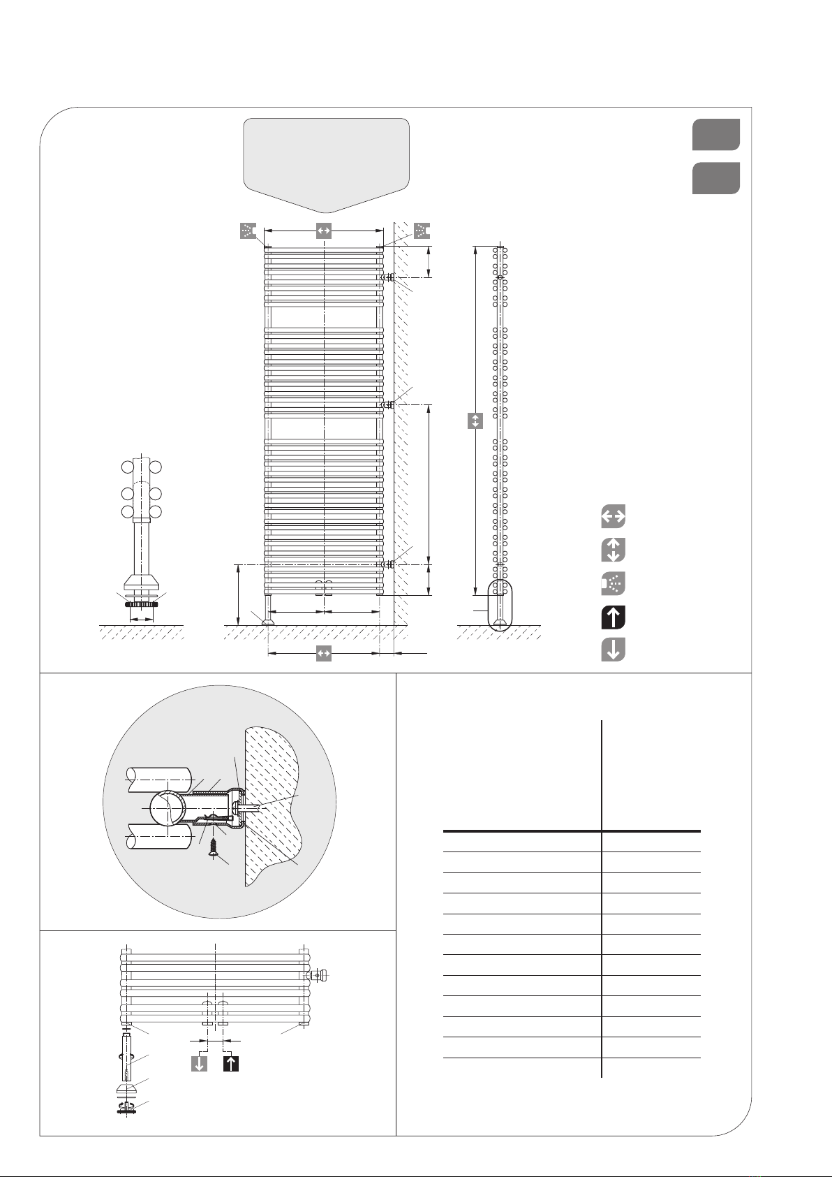
Le tubage doit être préparé en tenant compte des dimensions géométriques du radiateur design COSMO FLORENZ-T (soupapes, vissages) - cf. Abb. 1.
En cas d’utilisation d’une cartouche chauffante, cette dernière peut être étanchée dans le manchon I 1,2“. Pour cela, respecter les instructions de montage de la car-
touche chauffante. Les raccords non utilisés doivent être fermés à l’aide des bouchons inclus à l’emballage, la purge 1/2“ devant être montée à l’un des deux manchons
III.
Avant le montage du séparateur de pièce, veillez à prévoir le raccord de l’aller et du retour conformément à la Abb. 3.
MONTAGE
Fixer les écrous en tôle 1inclus à l’emballage sur les tubulures de montage 2 (Abb. 2). C’est valable pour les positions de montage Aet B, quand la hauteur du radiateur
est de 2154 mm. Visser solidement l’écartement au sol Davec l’anneau torique dans le manchon II. Fixer la rosette de recouvrement Favec l’anneau torique correspon-
dant (Abb. 3). Visser complètement la vis de réglage Edans le filetage M10 prévu à cet effet. Tracer et percer les trous Aet C- mèche de diamètre 10 - et placer les
chevilles conformément aux mesures auxquelles le radiateur sera accroché, Abb. 1. Cela vaut aussi pour la position de trou Bquand la hauteur est de 2154 mm.
Recommandations:
Veuillez mesurer au préalable l’écartement des tubulures de montage (Abb. 1) pour identifier le radiateur.
Au besoin (état du mur), les garnitures en plastique 3incluses à l’emballage sont à coller sur les pieds muraux 4 (Abb. 2) (veiller à ce que les emplacements à coller soient
propres!).
Fixer les pieds muraux 4et ajuster verticalement ces derniers, les alésages 5devant être positionnés conformément à la Abb. 2. Pour cela, les vis de montage au mur
6devraient être montées au milieu des trous longitudinaux (nous recommandons de contrôler l’écartement des pieds muraux montés avant le montage du radiateur au
mur).
Montage du radiateur design:
Insérer les tubulures de montage 2dans les pieds muraux 4et les visser lâchement à l’aide des vis en tôle. La distance d’avec le mur peut être variée grâce au trou
longitudinal du support de montage. Le trou longitudinal du disque mobile 8du pied mural permet de régler les pieds muraux en largeur de pose et en hauteur, dans le cas
où les raccords hydrauliques ne concorderaient pas exactement. En outre, le radiateur design peut être orienté horizontalement ou les inégalités du sol compensées en
dévissant la vis de réglage E.
Attention: Ne dévisser la vis que de 5 mm au maximum. Fixer la vis de maniement au sol à l’aide de vis hexagonales, presser l’anneau torique et la rosette de recouvre-
ment sur la vis de maniement. Serrer la vis en tôle 7. Effectuer le raccordement hydraulique du radiateur, Abb. 3.
Les normes suivantes doivent être respectées lors du montage du radiateur:
• DIN 55900: Pulvérisation dans les pièces humides
• VDI 2035: Prévention des dommages dans les installations avec systèmes de chauffage à eau chaude
• DIN 18017 Partie 3: Ventilation des salles de bains et des toilettes sans fenêtres
• EN 14336: Système de chauffage dans les bâtiments, Installation et commissionnement des systèmes de chauffage à eau
UTILISATION ET ENTRETIEN
• Les radiateurs design COSMO FLORENZ-T sont des produits de haute qualité qui ne servent pas seulement à chauffer les pièces mais peuvent également être
utilisés pour faire sécher des serviettes de toilette. Dans ce cas, il faut veiller à ce que leur surface soit chaude. Il ne faut utiliser que des textiles lavés avec de l’eau
et secs.
• Bien entendu, on ne doit pas grimper sur les radiateurs ni s’en servir comme d’appareils de sport.
• Pour nettoyer la surface des radiateurs, veillez à employer des produits non agressifs et non récurants.
• En cas de fonctionnement en mode électrique des radiateurs, il faut veiller à ce que la dilatation de l’eau chaude soit assurée jusqu’au récipient d’expansion, par
exemple en ouvrant la soupape de reflux. Pour éviter que la chaleur ne soit entraînée dans le réseau de chauf fage, il est recommandé de fermer la soupape du
thermostat dans ce cas. Naturellement, le mode de fonctionnement électrique ne doit être mis en marche qu’une fois le radiateur entièrement rempli d’eau.
• Pour des raisons de sécurité, le radiateur ne doit pas être recouvert intégralement lorsqu’il marche en mode électrique.
DESCRIPTION DU RADIATOR
• Les radiateurs de la série COSMO FLORENZ-T sont d‘élégants radiateurs design, convenant aux systèmes de chauffage central à eau chaude. La température de service maxi-
mum est de 110 °C et la surpression de service maximum de 10 bar.
• Le haut niveau de qualité constant est soumis à des contrôles internes et externes de façon continue.
• Les clients ne sont pas autorisés à effectuer des travaux ultérieurs sur les radiateurs (soudures, par exemple).
• Les produits de la gamme COSMO FLORENZ-T peuvent également être équipés d’un dispositif de chauffage électrique complémentaire, à condition de respecter les recomman-
dations suivantes: Abb. 4
• Dans le cadre de la gamme COSMO FLORENZ-T, le réglage hydraulique de la puissance/température de la pièce s’effectue grâce à un thermostat monté à l’extérieur du
radiateur.
Le système de fixation murale a été conçu pour des murs déjà finis.
CONDITIONS DE GARANTIE
• Rettig accorde une garantie de 10 ans en matière d‘étanchéité et de fonctionnement pour les radiateurs design de la gamme COSMO FLORENZ-T à partir du jour de la livraison
ainsi qu’une garantie de 5 ans pour les surfaces peintes.
• Les dommages survenus pendant le transport doivent être signalés au fournisseur au plus tard un jour ouvrable après la livraison.
• En cas d’un recours à la garantie, la facture doit être présentée. La garantie s’étend aux pièces comportant un défaut de matériel avéré ou devenues défectueuses en raison d’une
erreur de construction.
• L‘usure normale, les dommages survenus dans le cadre de catastrophes naturelles, les détériorations intentionnelles ou résultant de négligences, du non respect des instructions
d’assemblage, d’utilisation ou d’entretien sont exclus de la garantie.
• Aucune garantie n’est accordée pour des dommages survenus en raison d’une utilisation non conforme ou impropre, d’un montage et/ou d’une mise en service non appropriée
par des tiers, d’une manipulation impropre ou négligente, d’un outillage non approprié, de l’inclusion de corps étrangers, de travaux de construction défectueux, d’influences
chimiques, électrochimiques ou électriques, du moment où nous n’en sommes pas responsables.
• Dans le cas d’une erreur de construction ou d’un défaut de matériel avérés, Rettig se réserve le droit de réparer les parties défectueuses ou de les remplacer. Les pièces
échangées deviennent alors propriété de Rettig.
• Dans le cas où le client final a recours à la garantie (remise en état ou échange d‘une pièce), la durée de garantie n’est pas prolongée au delà de cette période en raison de sa
longue durée.
• Rettig se réserve le droit de modifier les spécifications techniques de ses produits sans avis préalable.

06
INSTALACJA I MONTAŻ GRZEJNIKÓW DEKORACYJNYCH
Instalacja i uruchomienie grzejnika dekoracyjnego COSMO FLORENCJA-T powinno zostać wykonane przez uprawnioną do tego rmę.Należy również uwzględnić obo-
wiązujące obecnie normy i przepisy. Podłączenie instalacji należy przygotować uwzględniając wymiary grzejnika oraz jego podłączenia.
WSKAZÓWKI
A W przypadku nie instalowania grzałki elektrycznej, należy mufę I oraz jed-ną z muf III zaślepić korkami a do drugiej z muf III wkręcić odpowietrznik (wszystkie korki są załączone do
wyposażenia dodatkowego).
B W przypadku instalowania grzałki elektrycznej, zaleca się w tym celu uży-cie mufy I. Należy przy tym przestrzegać wskazówek, zalecanych przez danego producenta grzałek, dotyczących
samego montażu grzałki elektrycznej.
MONTAŻ
Przyłącza zasilania i powrotu należy podłączyć zgodnie z Abb. 3. Nasadki metalowe 1 osadzić we wsporniki montażowe 2 (Abb. 2). Dla pozycji montażowej A względnie B przy wysokości
grzejnika 2154mm należy wkręcić stopę grzejnika D wraz z uszczelką w mufę II (Abb. 3). Nasunąć rozetę F z uszczelką na stopę grzejnika D(Abb. 3). Pokrętło poziomujące E wkręcić całko-
wicie w odpowiedni gwint M10 stopy grzejnika D. Oznaczyć żądaną pozycję Ai C. Za pomocą wiertła ø10 wywiercić otwory i zamontować w nich kołki rozporowe (Abb. 1). Dla grzejnika o
wysokości 2154mm także w
pozycji B.
Wskazówka:
W celu bezproblemowej instalacji należy bardzo dokładnie zmierzyć odstępy między wspornikami 2 (Abb. 1).
W razie potrzeby, zależnie od stanu ściany, można wykorzystać załączone do zestawu elementy wspomagające montaż z tworzywa sztucznego 3 i nakleić na wsporniki 4 (Abb. 2). Należy
zwrócić uwagę na czystość klejonych powierzchni.
Zamocować wsporniki ścienne 4, przy czym otwory 5 we wspornikach skierowane powinny być na zewnątrz oraz śruby służące do montażu do ściany 6 muszą zostać zamocowane w
samych wspornikach 4 (proponuje się skontrolowanie odstępów między wspornikami 4 przed zamontowaniem grzejnika). Osadzić wsporniki montażowe 2 we wspornikach ściennych 4 a
następnie zamocować je przy pomocy śrub metalowych 7 (służą one do określenia odległości od ściany).
W przypadku, gdy przyłącza zasilania i powrotu nie pasują idealnie do siebie, dobór odpowiedniej odległości regulowany jest przy pomocy podłużnego otworu w ruchomej blaszce 8
umieszczonej we wsporniku ściennym 4. Poprzez regulację pokrętłem poziomującym E można wypoziomować grzejnik, lub zapobiec problemom związanym z nierównością podłoża.
Uwaga:
Regulacja poziomu do maks. 5mm. Pokrętło poziomujące E przymocowywać do podłoża przy pomocy śrubokrętu. Rozetę F wraz z uszczelką nasunąć na pokrętło poziomujące E. Wspor-
niki montażowe 2 i ścienne 4 mocować przy pomocy śruby metalowej 6.
Grzejnik podłączyć do instalacji centralnego ogrzewania (Abb. 3).
OBSŁUGA I UTRZYMANIE CZYSTOŚCI
• Grzejniki dekoracyjne COSMO FLORENCJA-T są produktami wysokiej jakości, służącymi nie tylko do ogrzewania pomieszczeń, ale i do np. suszenia ręczników. Z tego też względu
nie należy zapominać, że posiadają one gorące powierzchnie.
• Nie zezwala się natomiast na używanie grzejników do innych celów, jak np. drabinki sportowe.
• Do czyszczenia powierzchni grzejników należy stosować środki o łagodnym działaniu, nie uszkadzających powierzchni.
• W razie użycia grzałki elektrycznej, przyrost objętości wody musi być skompensowany poprzez otwarcie zaworu powrotnego. Zaleca się także zamknięcie głowicy termostatycznej
na zasilaniu. Ogrzewanie elektryczne może zostać uruchomione tylko wtedy, gdy grzejnik wypełniony został całkowicie wodą.
• Jeżeli grzejnik działa jako elektryczny poprzez użycie grzałki elektrycznej, to ze względów technicznych oraz bezpieczeństwa nie może być całkowicie zakryty.
OPIS GRZEJNIKA
• Grzejniki COSMO FLORENCJA-T są eleganckimi, grzejnikami wzorniczymi. Przystosowane są do podłączenia w systemach centralnego ogrzewania przy maksymalnej temperatur-
ze pracy 110°C oraz maksymalnym ciśnieniu roboczym 1,0MPa (10 bar).
• Niezmienne, wysokie standardy jakości podlegają ciągłej kontroli służb wewnętrznych, jak i zewnętrznych.
• Nie zezwala się na prace naprawcze przy grzejnikach (np. spawanie) wykonywane na własną rękę, a także inne działania mogące powodować deformację grzejnika, lub zniszczenie
powłoki lakierniczej.
• Rodzina produktów COSMO FLORENCJA-T może zostać wyposażona w grzałkę elektryczną, przy czym należy zwrócić uwagę na następujące dane: Abb. 4
• Regulacja temperatury w pomieszczeniu odbywa się przy użyciu głowicy termostatycznej zamontowanej na zaworze grzejnikowym.
Idea montażu na ścianie pomyślana jest jako system przeznaczony dla gotowych ścian.
WARUNKI GWARANCJI
• Na grzejniki dekoracyjne COSMO FLORENCJA-T udzielana jest 10-letnia gwarancja na szczelność grzejnika oraz 5-letnia na zastosowaną powłokę na powierzchni grzejnika.
• Gwarancja jest liczona od dnia zakupu, potwierdzonego dowodem zakupu, np. fakturą.
• Szkody powstałe w wyniku transportu powinny zostać zgłoszone do dostawcy grzejnika najpóźniej następnego dnia roboczego po dacie zakupu towaru.
• Gwarancja obejmuje grzejnik, lub jego części, których wadliwe działanie spowodowane jest jednoznacznie wadą materiałową, lub których nieprawidłowe działanie wynikło z
wadliwego wyrobu.
• Normalne ślady zużycia, szkody powstałe w wyniku działania siły wyższej, szkody spowodowane umyślnie, lub nieumyślnie poprzez nieprzestrzeganie zasad montażu, lub użycia nie
podlegają warunkom gwarancji.
• Gwarancja nie obejmuje szkód powstałych wskutek nieprawidłowego montażu, nieprawidłowej eksploatacji i/lub działalności osób trzecich, błędnych lub nieodpowiednich
narzędzi, przedostania się ciał obcych do wnętrza, błędnych robót budowlanych, oddziaływań chemicznych, elektrochemicznych i elektrycznych, o ile nie są one spowodowane z
winy producenta.
• W przypadku wyrobu uznanego przez producenta za wybrakowany ze względu na budowę lub wady materiałowe, producent zastrzega sobie prawo do wymiany, lub naprawy
wybrakowanych części, lub samego grzejnika. Rzeczy podlegające wymianie stają się własnością producenta.
• Okres gwarancji nie zostaje przedłużony o czas potrzebny do naprawy/wymiany produktu, lub przekazania części zamiennych.
• Reg zastrzega sobie prawo do zmiany parametrów technicznych swoich wyrobów.
PL

MONTAGE- UND BETRIEBSANLEITUNG 07
RO
INSTALARE ŞI MONTAJ COSMO
Montajul şi punerea în funcţiune a radiatorului design COSMO FLORENZ-T trebuie făcute de către o societate autorizată. De asemenea, trebuie respectate standardele
şi normele naţionale din domeniul electrotehnic, cum ar ÖVE şi VDE.
Pregăţi sistemul de distribuţie a ţevilor ţinând cont de dimensiunile şi geometria radiatorului design, cât şi de elementele de conectare (robineţi, racorduri) (Abb. 1).
Dacă se foloseşte un cartuş caloric, acesta trebuie cuplat în unul din racordurile de 1/2”I, respectând instrucţiunile de montaj.
Racordurile neulizate trebuie blindate folosind dopurile incluse în furnitură, robinetul de golire de 1/2” cuplându-se într-una din cele două mufe III. Înainte de a monta separatorul,
trebuie reţinut că turul şi returul instalaţiei vor corespunde Abb.3.
MONTAJUL
Fixaţi piuliţele 1 în ştuţurile de montaj 2 (Abb. 2). La fel se procedează şi la poziţiile de montaj A şi B, când înălţimea radiatorului este de 2154 mm. Înşurubaţi strâns ecartamentul la sol D
în mufa II. Fixaţi rozeta de acoperire F împreună cu O- ring -ul corespunzător (Abb. 3). Înşurubaţi complet şurubul de reglaj E în gaura letată M10 prevăzută.
Marcaţi şi faceţi găurile pentru poziţia A şi C – gaura ø10 – şi poziţionaţi diblurile în funcţie de mărimea masei suspendate. (Abb. 1). Având o înălţime totală de 2154 mm, acestea sunt
valabile şi în cazul poziţiei B.
Recomandare:
Vericaţi în primul rând distanţa între ştuţuri, pentru a putea determina modelul radiatorului (Abb. 1).
Dacă e nevoie, în funcţie de starea peretelui, adăugaţi elementul de xare 3, din plasc transparent, pe perete 4 (Abb. 2). Asiguraţi-vă că suprafaţa de adeziune este curată.
Fixaţi şi aliniaţi vercal baza inferioară pe perete 4; gaura de scurgere 5 de la baza peretelui trebuie îndreptată conform Abb. 2. Şuruburile de xare 6 trebuie plasate în centrul găurilor
longitudinale ale suportului mural. (Vă recomandăm să vericaţi spaţiul dintre suporturile murale, înainte de a monta radiatorul pe perete).
Dacă baza inferioară B este folosită ca şi distanţier, cuplaţi-o la ştuţuri cu ajutorul şuruburilor 7. Montaţi radiatorului pe perete 4 introducând partea superioară a suportului de montaj 2
în baza dinspre perete A – şi racordaţi-o lejer cu ajutorul unui şurub din oţel 7. Distanţa până la perete poate varia în funcţie de găurile din suportul de instalare. Dacă partea hidraulică
nu se potriveşte perfect, înălţimea şi lungimea pot reglate cu ajutorul găurii alungite de pe plăcuţa situată pe suport 8. În plus, radiatorul design poate aliniat orizontal sau poate
compensa neregularităţile solului ajustând şurubul de reglaj E.
Atenţie: Ajustaţi şurubul de reglaj cu maxim 5 mm. Fixaţi şurubul la sol cu ajutorul şuruburilor hexagonale. Apăsaţi O- ring - ul şi rozeta de acoperire pe şurubul de reglaj.
Strângeţi şurubul din oţel. Faceţi racordul hidraulic al radiatorului.
UTILIZARE ŞI ÎNTREŢINERE
• Radiatoarele COSMO FLORENZ-T sunt produse de înaltă calitate care nu doar încălzesc încăperi, ci pot ulizate şi pentru a usca prosoape. Trebuie reţinut că suprafeţele sunt
erbinţi. Pot puse la uscat numai texle spălate în apă.
• Bineînţeles, radiatoarele nu pot ulizate ca şi echipamente de sport.
• Suprafeţele radiatoarelor trebuie curăţate cu soluţii ancorozive.
• În cazul funcţionării electrice a radiatoarelor, trebuie asigurată dilatarea apei în vasul de expansiune, prin deschiderea supapei de uni-sens. Pentru a evita transferul căldurii în
sistem, este recomandabil să se închidă robinetul termostac. Bineînţeles, radiatorul electric poate pus în funcţiune numai după ce a fost complet umplut cu apă.
• Din move de siguranţă, radiatorul nu trebuie acoperit în întregime, în cazul în care funcţionează electric.
DESCRIEREA RADIATORULUI
• Radiatoarele COSMO FLORENZ-T sunt radiatoare design elegante pentru băi, adecvate sistemelor de încălzire centrală, cu o temperatură maximă de funcţionare de 110°C şi o
presiune maximă de 10 bar.
• Standardul înalt de calitate este supus unor controale connue, interne şi externe.
• Beneciarilor le sunt interzise intervenţiile ulterioare asupra radiatoarelor. (ex: sudura).
• Produselor COSMO FLORENZ-T li se poate ataşa un element electric de încălzire adiţional, cu condiţia ca următoarele recomandări să e respectate:
• Reglajul hidraulic – controlul temperaturii pentru radiatoarele din gama COSMO FLORENZ-T este asigurat de un termostat montat în exteriorul radiatorului.
Sistemul de instalare murală a fost conceput pentru pereţi nisaţi.
CONDIŢII DE GARANŢIE
• Reg acordă o garanţie de 10 ani din punct de vedere al etanşeităţii şi al funcţionării radiatoarelor design COSMO FLORENZ-T, din ziua livrării, şi o garanţie de 5 ani pentru
suprafeţele vopsite sau metalizate.
• Deteriorarea din mpul transportului trebuie anunţată furnizorului cel târziu următoarea zi lucrătoare după livrare.
• În cazul recurgerii la garanţie, trebuie prezentată factura.
• Garanţia acoperă piesele componente cu defecte materiale dovedite sau care sau defectat ca urmare unei erori de construcţie.
• Sunt excluse de la garanţie uzura normală, defecţiunile provocate de catastrofe naturale, cele provocate cu bună şinţă, sau din neglijenţă, incompabilitatea cu instalaţia, nere-
spectarea instrucţiunilor de montaj, funcţionarea şi întreţinerea.
• Nu se oferă garanţie pentru defecţiuni rezultând din ulizarea improprie sau neadecvată, din montajul sau punerea în funcţiune improprie de către terţi, din manipularea negli-
jentă, agenţi de operare nepotriviţi, corpi străini în apă, montaj defectuos, agenţi chimici, electrochimici sau electrici, de care noi nu suntem responsabili.
• În cazul în care se constată defecţiuni de construcţie sau materiale defecte, Reg îşi rezervă dreptul de a repara piesele în cauză, sau să le înlocuiască. Piesele schimbate devin
proprietatea Reg.
• În cazul în care beneciarul a apelat la garanţie, (reparaţie sau înlocuire piesă de schimb), garanţia nu va exnsă.
• Reg îşi rezervă dreptul de a modica specicaţiile tehnice ale produselor, fără înşinţare prealabilă.

COSMO GMBH
Brandstücken 31 ·22549 Hamburg
info@cosmo-info.de
www.cosmo-info.de
Table of contents
Languages:
Other Cosmo Bathroom Fixture manuals
Popular Bathroom Fixture manuals by other brands

FORENO
FORENO Primus PSL9 quick start guide

Sanela
Sanela SLSN 22D Instructions for use

Bradley
Bradley E19-130 installation guide

Franke
Franke AQUAFIT Installation and operating instructions

Swiss Madison
Swiss Madison Monaco SM-PS307 installation instructions

VADO
VADO ORA ORA-MFSRKWO-RO-CP installation guide