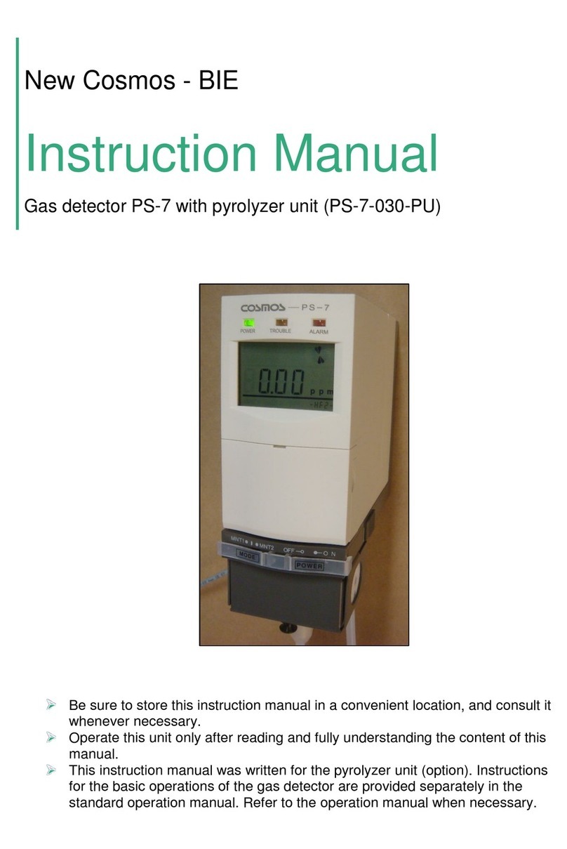
Cosmos XPS-7 User manual

●Store this operation manual in a convenient location, and consult it
whenever necessary.
●Operate the product only after reading and fully understanding the
content of this manual.
Document No.
XPS-7ET (00)
December 2004

TABLEOFCONTENTS
1. Introduction.........................................................................................................1
2.ContentsofThis Package..................................................................................2
3. Sensor Units.......................................................................................................3
4.Component NamesandFunctions....................................................................4
5. OperatingProcedure..........................................................................................6
5. OperatingProcedure..........................................................................................7
5-1Inserting Batteries.........................................................................................7
5-2Installing theSensorUnit..............................................................................8
5-2Installing theSensorUnit..............................................................................9
5-3Turning theGas DetectorON................................................................... 10
5-4Detection..................................................................................................10
5-5EndingDetection......................................................................................10
6. LoggerFunction.............................................................................................11
7.Replacing theFilter......................................................................................... 12
8.DailyandPeriodic Inspections.......................................................................13
9. Troubleshooting..............................................................................................13
10.ConsummablePartsandOptions................................................................13
11.WarrantyandRegistrationCard...................................................................14
12.Specifications................................................................................................14

1
1. Introduction
Thank you for purchasing the XPS-7 Semiconductor Plant Gas Detector. To ensure correct
operation, pleasereadthisoperationmanual carefully.
Thisproduct is designed to detect gas leaks insemiconductormanufacturingplants. Sensor units
(purchasedseparately)canbeswitchedtodetect avarietyofgases.
Readandbesureyoufullyunderstandthismanualevenif youhaveusedaGasDetectorbefore.
Do not use the Gas Detector for any purpose other than that for which it was intended. Do not
attempttousetheproductinawayotherthanthatdescribedinthismanual.
●Explanation ofSymbols
This manual uses the following symbols. Their meanings must be understood and observed to
ensuresafeoperationoftheGasDetector.
! Danger
Indicates an impending hazardous situation that,if not avoided, could result
inseriousinjuryordeath.
!Warning
Indicates a potentially hazardous situationthat, if not avoided, could result in
seriousinjuryordeath.
!Caution
Indicates a potentially hazardous situationthat, if not avoided, could result in
minorinjuryorphysicaldamage.
Indicatesoperationaladviceand/orinstructions.
●Observe the following precautions to ensure safe operation of the
Detector.
!Warning:TheGasDetectorisnotexplosion-proofandmustbeinstalledinanon-hazardouslocation.
!Caution:TheGasDetectorisnotdrip-proofandmustbeinstalledinalocationfreefromsplashingwater.
!Caution:DonotallowtheGasDetectortobesubjectedtomechanicalshockbybeingdroppedorstruck.
!Caution:The Gas Detector must be turnedON in a clean-airenvironment. Otherwise, the performance of the
Detectormaybeimpairedandnormaldetectionmaynotbepossible.
!Caution The shelf life of the sensor unit is six months. Always check the sensor unit to besure its life has not
expiredpriortouse.Normaldetectionmaynotbepossibleifanexpiredsensorunitisinstalled.
Note

2
●Observe the following precautions for the storage environment and
methodof storing the GasDetector.
2. Contents of This Package
The following components are included with the Gas Detector. Ensure that all components are
present beforeattemptingtousetheDetector.
Warning: Donotstorethe Gas Detector for long periods in locations with high temperatures or high humidity.
Otherwise,theperformanceoftheDetectormaybeimpaired.
Caution: Do not subject the Gas Detector to sudden changes in temperature or humidity. Otherwise, the
performanceoftheDetectormaybeimpaired.
Caution: IftheGasDetectorisnottobeusedforalongtime,removethebatteriesbeforestoringit.
□Gas Detector.........................................1□Filters...................................................2
□Shoulderstrap.......................................1□AAalkalinebatteries...........................4
□Gas inlettube.........................................1□Inspectionresults................................1
□Operation manual..................................1□Registrationcard andwarranty..........1
!
!
!

3
3. Sensor Units
Alarm setting
Model Detectedgases FS 1st level 2nd level
XDS-7NH NH3Ammonia 100ppm 12ppm 25ppm
XDS-7SH SiH4Silane 25ppm 2.5ppm 5ppm
XDS7DC SiH2
Cl2Dichlorosilane 25ppm 2.5ppm 5ppm
XDS-7AH AsH3Arsine 250ppb 25ppb 50ppb
XDS-7PH PH3Phosphine
1ppm 0.15ppm 0.3ppm
XDS-7BH B2H6Diborane 500ppb 50ppb 100ppb
XDS-7SE H2Se Hydrogen
selenide 250ppb 25ppb 50ppb
XDS7GH GeH4Germane 1ppm 0.1ppm 0.2ppm
XDS-7CL Cl2Chlorine 5ppm 0.25ppm 0.5ppm
XDS-7CF ClF3Chlorine
trifluoride 1ppm 0.05ppm 0.1ppm
XDS-7HC HCl Hydrogen
chloride 25ppm 2.5ppm 5ppm
XDS-7HF HF Hydrogen
fluoride 10ppm 1.5ppm 3ppm
XDS-7HB HBr Hydrogen
bromide 10ppm 1.5ppm 3ppm
XDS-7NO NO Nitrogen
monoxide
100ppm 12ppm 25ppm
XDS-7HS H2S Hydrogen
sulfide 50ppm 5ppm 10ppm
XDS-7CO CO Carbon
monoxide
250ppm 12.5ppm 25ppm
XDS-7DS Si2H6Disilane 25ppm 2.5ppm 5ppm
XDS-7F2 F2Fluorine 5ppm 0.5ppm 1ppm
XDS-7OZ O3Ozone 1ppm 0.05ppm 0.1ppm
Contact an authorized representative of New Cosmos regarding other detectable gases not listed in
thetable.

4
4. Component Names and Functions
MainUnit
No.
Name Function
①Power lamp (green) Flashes during the warm up period after the power is turned ON
andremains litduringoperation.
②Troublelamp (yellow) Flashes when an error occurs.
③Alarmlamp(red) Flashes when the detected gas concentration reaches the alarm
point.
④LCD display Indicates gasconcentration and otherinformation.
⑤Keyswitchcover Lightly pull the cover toward you to open it and access the key
switches.
⑥Buzzerspeaker
⑦Gasinlet Sampledgasaspirationinlet.(6dia.)Attachestothegasinlettube.
⑧Gasoutlet Exhaustoutletforsampledgas (6dia.)
⑨Adapter connector Connects to the 100-VAC/6-VDC adapter plug.
⑩Batterycover Liftthesnap lockand open thecover toinsertbatteries.
⑪Sensorcover Liftthesnap lockand open thecover toinsertthesensor unit.
⑫Sensor window Used tocheckthesensor unit that is installed.
⑬LED(red)
(Batterycheck) Lit if the key switch cover is open with the Gas Detector turned
OFF, whenbatteries areinserted, or when batteries arelow.
①
④
③
②
⑤
⑥
⑦
⑧
⑨
⑩
⑪
⑫
⑬

5
KeySwitches
No.
Name Function
①Power switch Press andhold to turntheGas Detector ON andOFF.
②Alarmsetting indicator
switch
Used to check the alarm settings. Press the switch repeatedly to
displaythefirst level alarm setting, secondlevel alarmsetting, and
gasconcentration.
③Buzzerstopswitch
④Zerocalibrationswitch
Press andholdtoadjustthezeropoint automatically.
⑤CNjack Connects tothe plug of aCA-7 Communications Adapter (option)
usedforlog datacollection.
⑥Specialcommand
switch Usedwiththelogger function.
⑦UP/DOWNswitches Used tosetthestarttimeand otherloggerfunctionsettings.
LCDDisplay
②
③
⑤
①
④
⑥
⑦
●Battery indicator
Indicatesthebatterycapacity.
●Flowratedrop
Litwhentheflowratedrops.
●Gas samplingflow rate
Normal:RUN,Error:STOP
●Gas concentration alarms
Lit when the detected gas concentration
reachesthealarmpoint.
Full
Exhausted(flashing)
・
・
・
●Sensortrouble
Litwhenasensorerror occurs.
●Gas concentration
Indicatesthegasconcentrationandunit.
●Gas concentration bar graph
Eachbar is 5% offull scale.Bars lit all theway
totherightindicatefullscale.
●Log indicator
Litwhenthelogfunctionis operating.

6
GasInlet Tube
AttachingandRemovingtheGasInletTube
●Attaching
Insert the tube into the coupling on the Gas Detector inlet and secure it in place with the
locking tab toseal the edge of thetube. After the tube is attached, make sure that it will not
pullout.
●Removing
Press in thereleasering onthecouplingandsimultaneouslypullout thegas inlet tube.
●Gasinlettube
Onemetertubethatconnectstothe
GasDetectorinlet
●Gas samplingpipe
Thisisthegasinlet.
●Filtercase
Containsthefilter(FE-112).
Note
Attaching Removing

7
5. Operating Procedure
Inspect the Gas Detector daily before using it.(Refer to page13.) If theDetector is used without
first performing the inspection, normal detection may not be possible and leaks may not be
detected.
5-1Inserting Batteries
①Lift thesnaplockonthebatterycoverandpullthecovertowardyoutoopenit.
②InsertthefourAAalkalinebatteriesprovidedandmakesuretheyareinsertedaccordingto
thepolarityindicatedinthebatterycompartment.
③Closethebatterycover.
!Caution:The Gas Detector must be turned ONin a clean-air environment.Otherwise, the performance of the
Detectormaybeimpairedandnormaldetectionmaynotbepossible.
●Battery cover
Liftthesnaplockandopenthecover.
●Battery
compartment
!Warning:Replace all four batteries at thesame time withfresh, new batteries.
Alsomakesurethatthereplacement batteries areallthesamebrand andtype.

8
!Caution:Always replacethebatteries inthefollowingsituations.
①The battery indicator shows a flashing box (□) when the Gas Detector is ON.
(RefertoLCDdisplayon page5.)
②Nothing operates whentheGas Detector isON.
③ThebatterycheckLED (red) is glowingverybrightly (as bright as ①above) when
theGas Detector isOFF. (Refer toitem ⑬on page4.)

9
5-2Installing theSensorUnit
①Lift thesnaplockonthesensorcoverandpullthecovertowardyoutoopenit.
②Note the position of the connector and the mounting slot as you push the sensor unit into
place.
③Whenthesensor unitissecurelyinplace, closethesensor cover.
●Sensorcover
Liftthesnaplockandopenthecover.
●Sensor mounting slot
●Connector
●Sensor
!Caution: ●If the Gas Detector is used without a properly seated sensor unit, the Gas
Detector will not be air-tight and normal detection may not be possible. Make
surethe unitis properlyseated.
● Use the special power block (purchased separately) to supply power to the
sensor unit.A sensor unit that does not have power toit cannot detect gases and
may cause the sensor trouble indicator to light. Asensor unit installed in theGas
Detector is powered even if the Gas Detector is turned OFF, as long as the
batteriesarecharged.
● When a sensor unit is replaced (shipped from the plant), install it in the Gas
Detector or connect it to thepower blocktosupply asufficient amount of power to
thenew unit beforeturningONthe Gas Detector and using it for thefirsttime.
● This Gas Detector uses XDS-7 sensor units and is not compatible with CDS-7,
COS-7, CHS-7 orany other sensor units.

10
5-3Turning theGasDetectorON
①Press and hold the power switch. The buzzer sounds, the green power lamp flashes, and
self-diagnosisbegins.Thediagnosticprocedurelastsabout 30seconds.
②When self-diagnosis is completed, zero adjustment is performed automatically, the green
powerlamplights,andtheunitisreadytodetect gas.
5-4Detection
Place the gas sampling pipe near the target detection area. When the unit detects gas, the
concentration of the detected gas is displayed. If the detected gas concentration level reaches the
alarm point,thealarm lamp lights andthebuzzer sounds.
5-5EndingDetection
Whendetectioniscompleted,placetheGasDetector inaclean-airenvironment andallowittodraw
in clean air until the concentration indicator reads zero. Press and hold the power switch until the
DetectorturnsOFF.
!Caution: ●TheGas Detector mustbe turned ON in aclean-air environment. Do not allow the
Detectortodrawingas whileit is warming up.Otherwise, zeroadjustment willnot
beperformed properlyandnormaldetectionwillnotbepossible.
● Wait at least1s beforeturningtheGas DetectorbackONafter a power failure.
!Caution:Donot allow water or other liquids toenter theGas Detector. Anyliquid will cause the
GasDetectortofail.
!Caution: After an adsorbent gas has been detected, replace the filter with a new one before
attempting to detect another gas. Normal detection is not possible with a
contaminatedfilter.

11
6. Logger Function
TheGas Detector can recordup to 22 hoursof detection data. Therecorded data can bewritten to
a personal computer using optional components that can be purchased separately. (See 13.
ConsumablePartsandOptions.)
②Press the SPECIAL COMMAND switch and the digit that will
change starts to flash. Use the UP/DOWN and SPECIAL
COMMANDswitchestoset thelogstart time.
④To end log recording, press theBUZZER STOPswitch while
LOG is displayed on the lower right corner of the LCD display.
MNT1willnolongerbedisplayedandlogrecordingwillstop.
Example: Enter the numbers shown in the display on the right
toset thelogstarttimeat1:20pm.
③Afterthetimehasbeenset,pressandholdtheZERO switch.
MNT1 (maintenancemode 1) will be displayed on the lower left
corneroftheLCDdisplayandlogrecordingwillbegin.
①PresstheDOWNswitch(▼)onceinRUNmode.
LOG will be displayed on the lower right corner of the LCD
displayandthelogstarttimecanbeentered.
Note
●Maximum gasconcentration isrecordedevery 10 safter loggingbegins.
●NewlogdataisstoredintheGasDetectorbyoverwritingolddata.
●Thelogger functionterminateswhentheGasDetectoristurnedOFF.
●Datesettingsarenot supported.
●Refer to theXPS-7LogData Collection SoftwareintheXPS-7LOperationManual
fortheprocedureusedtowritelogdatatoapersonal computer.

12
7. Replacing the Filter
①Openthefilter casebytwistingtheendwiththegassamplingpipe.
②UseapairoftweezerstoremovetheO ringandfilter.
③Insert anewfilter andtheOring.
④Reassemblethefilter case.
●Filtercase
Twistthefiltercasetoopenit.
●Oring
●
Filter
Note
●Pressing the UP (▲) or DOWN (▼) switch repeatedly in RUN mode changes
thedisplay onthe bottom right corner of theLCD displayasshown below.These
arefactoryadjustments that arenot availablefor user application

13
8. Daily and Periodic Inspections
9. Troubleshooting
Problem Cause Remedy Reference
Batterypolarityisreversed. Correctthebatterypolarity.
Thebatteries arelow. Replacethebatteries. Page7
The power does not
come ON even when the
power switch is pressed
andheld. The sensor unit is not
installed. Install asensor unit. Page9
Abnormal drop in the
flowrate Thefilter is clogged. Replacethefilter withanew one. Page12
There is not enough power
tothesensorunit. Make sure the sensor unit has
sufficientpower when installing it. Page9
Sensorerror
The shelf life of the sensor
unithas expired. Replace thesensor unit with anew
one. Page9
10. Consumable Parts and Options
Partname Model number Remarks
Sensorunit XDS-7□Contact an authorized representative of New Cosmos
regardinggasesthatcanbedetected.
Filters (10perset) FE-112
100-VAC /6-VDC adapter Special adapter for 100 VAC.
Power block EC-7 Provides power for uptosixsensor units at onetime.
Log datacollectionsoftware XPS7L
Communications adapter CA-7
Serialcrossover cable KRS-L09-2K Requiredtowritelogdatatoapersonalcomputer.
CheckingtheGasInlet Tube
Isthetubedamaged?If so,replaceitwithanewone.
Checkingthe Filter
・If thefilter isdirtyanddiscolored,replaceitwithanewone.
DailyInspections
Note
Clean theGas Detector by gentlywiping it with aclothdampened with water.
To maintain accuracy, it is recommended that the Gas Detector be given periodic
inspections and adjustments at least oncea year by an authorized representativeof New
Cosmos.
Replacethesensoruniteverysixmonths.
PeriodicInspections

14
11. Warranty
Warranty-One(1)year from thedateof purchase
Thank you forpurchasing our product. New CosmosElectricCompany Limited, warrants its products
against any defects in materials and workmanship under normal use and operating conditions for a
periodofoneyear fromthedateof purchase:
(1) Limitationof warranty
All obligations and liabilities under this warranty are limited to repairing or replacing at the manufacturer's
option of the allegedly defective items returned to us, with carrier charges prepaid. All repairs and
replacements are madesubject to ourfactory inspection of the returned items. No liability is accepted for the
consequential damage.
(2) Exempted from warranty: failures or damage that are caused by (loss or damage occurred from any of the
followingreasons mayberepaired onlyat cost)
1) misuse, mishandling, or user's intentional or unintentional negligence,
2) disasters including fire, earthquake, wind/flood, snow, abnormal weather, abnormally high voltage,
abnormal radio wave, or other weather or act of God,
3) any other reasons that arenot attributableto themanufacturer,
4) repair or modification madebythecustomers,or
5) consumables or afailuretoreplaceconsumables when necessary.
12. Specifications
Detected gases Gasesfound in semiconductor manufacturingplants
Detectionprinciple
Controlledpotential electrolysis
Gassampling
method Pump suction method
Detection range As perspecifications
Concentration
displaymethod LCD display
Detection
accuracy(See
note1.) ±10%of FS
Responsetime
(Seenote1.) Within60s (60%response)
Power supply FourAAalkalinebatteries or 6 VDC (witha100-VAC/6-VDC adapter)
Batteryoperating
time(Seenote2.)
At least 12 hours of continuous operation (at 20°C with alkaline batteries and no
alarms)
Operating
temperaturerange
0to40°C
Dimensions W62xH 150xD 128mm(projectedportionsexcluded)
Weight Approx. 1.3kg
Note1: Thedetection accuracyandresponsetimeweremeasuredunderidenticaldetectionconditions.
Note2: The operating time of the batteries depends on factors such as environmental conditions, operating
conditions,thestoragetime, andthemanufacturer.

15
New
CosmosElectricCo.,Ltd.
Manual Revision History
Edition No. Date Revisions
XPS-7ET(00) December2004 0
Additionalcopies of this Operation Manualare available.
Contact thefollowing addressfor orderinginformation.
Distributor: Manufacturer:
New Cosmos Electric Co.,Ltd.
2-5-4 Mitsuya-nakaYodogawa-ku
Osaka 532-0036,Japan
Phone 81-6-6309-1505
Fax 81-6-6308-0371
e-info@new-cosmos.co.jp
http://www.new-cosmos.co.jp
Other manuals for XPS-7
1
Table of contents
Other Cosmos Gas Detector manuals