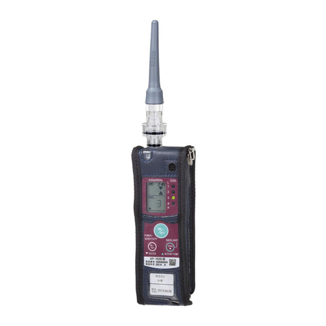
Cosmos XP-704 III User manual

Keep this instruction manual available for quick reference when
needed.
Read this instruction manual and thoroughly understand before
using the product.
HCFC Detecto
r

- 1 -
-Included in this Package -
The package includes the items listed in the following table. Before using the Gas Leak
Detector, be sure to check that all items have been provided. Every precaution has been
taken in preparing the Gas Leak Detector. However, if any items are missing or damaged,
please contact your New Cosmos distributor. Replacements for any missing or damaged
items will be sent.
.
●Options (Sold Separately) *1
*1 Refer to page 18 for details of options.
Name Quantity
Gas Leak Detector (with soft case) 1
DF-114 Drain Filter 1
Replacement FE-2 Filter Element 1
AT-2G Gas Probe 1
FE-106 Dust filter 1
EG-10 Test Gas 1
Hand Strap 1
Size AA Alkaline Batteries 2
Instruction Manual 1
Operation Guide 1
Inspection Report 1
Name Model
Gas Collector AT-6
Gas Collector AT-7A
Telescopic Probe RP-4
Gas Collection Set ATS-6
Table of Contents
Included in this Package........................................................................... 1
1. Introduction............................................................................................ 2
Symbols ................................................................................................... 2
Safe Operation ......................................................................................... 3
2. Part Names and Functions.................................................................... 4
3. Operating Procedure ............................................................................. 7
Drain Filter................................................................................................ 7
Operating Procedure................................................................................ 8
Silent Mode ............................................................................................ 11
Deactivating the Alarm Buzzer ............................................................... 12
Lighting the Backlight ............................................................................. 12
4. Error Displays ...................................................................................... 13
5. Replacement of Consumable Parts.................................................... 14
Filter Element Replacement ................................................................... 14
Dust Filter Replacement......................................................................... 15
Battery Replacement.............................................................................. 16
6. Maintenance Check ............................................................................. 17
Daily Check ............................................................................................ 17
Periodic Inspection................................................................................. 17
Consumable Parts, Replacement Parts, and Options ............................ 18
7. Troubleshooting................................................................................... 19
8. Warranty ............................................................................................... 20
9. Specifications ...................................................................................... 21
10. Detection Principle ............................................................................ 22

- 3 -
Safe Operation
Be sure to observe the following to use the product safely and properly.
During the gas detection, there is a possibility of the target gas being
emitted from the outlet of Gas Leak Detector.
Do not breathe in gas.
Do not bring fire close to the Gas Leak Detector.
DANGER
Be sure to turn ON the power in clean air. Since zero adjustment is
performed automatically, the proper gas concentration will not be
displayed when turning on the power in gas atmosphere.
Do not block the inlet and outlet. Otherwise, it may not be able to detect
properly
Do not allow water or liquids to enter the Gas Leak Detector. It may
cause interference to the gas detection and may damage the Gas Leak
Detector.
Make sure that Filter Element is clean. If the Filter Element is dirty or
wet, it may not be able to detect properly.
Do not block the buzzer hole. It will muffle the alarm.
Since XP-704III does not have an explosion-proof construction, do not
use in hazardous area.
WARNING
Remove the batteries if the Gas Leak Detector will not be used for an
extended period of time.
Check the remaining battery charge periodically (approximately once a
month) even if the Gas Leak Detector remains unused for an extended
period of time. Replace batteries if the batteries are leaking when the
remaining battery charge is low.
To avoid damaging its performance, never attempt to disassemble,
alter, or change the structure or electric circuits of the Gas Leak
Detector.
Do not leave the Gas Leak Detector in hot and humid environment for
a long period of time. It may affect its performance.
Do not use the Gas Leak Detector in places where the temperature or
humidity fluctuates greatly. It may affect its performance.
Keep the Gas Leak Detector away from significant changes in
atmospheric pressure. It may affect the performance of or damage the
sensor.
Avoid high mechanical impacts, dropping and throwing the Gas Leak
Detector. It may affect its performance.
In case of dew condensation, conduct an inspection after drying the
Gas Leak Detector completely before use.
Do not use the Gas Leak Detector near silicon sealing agents or in
atmosphere containing silicon gas. It may affect its performance.
The Gas Leak Detector may detect gas or solvent vapors other than
the target gas. Consider the inspection environment when using the
Gas Leak Detector.
Detecting high concentration of SO2or Cl2may decrease the sensor
life or increase errors.
It has a simple drip-proof structure by using a soft case. Avoid
exposure to water as much as possible
Keep away from the wireless applications. It may start sounding alarm
near the wireless applications while in use.
CAUTION
- 2 -
1. Introduction
Thank you for purchasing a New Cosmos Gas Leak Detector. Please read this Instruction
Manual thoroughly before using the Gas Leak Detector to help prevent gas leakage
accidents and to aid in safety inspections.
XP-704III Gas Leak Detector detects leakage of Hydrochlorofluorocarbon. When the gas
concentration exceeds the set value, a buzzer and lamp provide notification of the gas
leakage to help prevent gas leak accidents.
Read and understand thoroughly this Instruction Manual regardless of your experience with
using Gas Leak Detectors.
Do not use this Gas Leak Detector for improper purpose. Do not use this Gas Leak
Detector in undocumented way in this manual.
Symbols
The following symbols are used for safety purposes:
Indicates an imminently hazardous situation, which will result in death
or serious injury if not avoided.
Indicates a potentially hazardous situation, which will result in death
or serious injury if not avoided.
Indicates a potentially hazardous situation, which may result in minor
injury or property damage if not avoided.
Operational advice and/or instruction.
WARNING
DANGER
CAUTION
NOTE

- 5 -
No. Name Functions
1 AT-2G Gas Probe Gas inlet.
2 DF-114 Drain Filter Protects the Gas Leak Detector from water, dust,
and other foreign matter.
3 FE-106 Dust Filter Protects the Gas Leak Detector from fine dust,
sand, and other foreign matter.
4 Outlet Gas outlet to exhaust sampled gas.
5 POWER/ SENSITIVITY Button Turns the power ON and OFF.
Sets the detection sensitivity level.
6 BUZZER Button
Turns the alarm buzzer and operation sound ON
and OFF.
Switches the gas types for two-gas model.
7 ZERO/ RESTART PUMP/
BACKLIGHT Button
Restarts pump operation after a pump error. Also
lights the LCD backlight and displays the target gas
name on the LCD.
8 Alarm/ Error Lamps (red)
Light up or flash when detecting gas leakage. The
flashing frequency increases as the concentration
of the gas leak increases. The lamps light if the
concentration is very high. These lamps also flash
when an error occurs in the pump or sensor.
9 Buzzer hole The buzzer sounds.
10
LCD
Displays the gas sensitivity and messages.
(a) The remaining battery charge is displayed.
Battery charge:
High . . . . . . . . . . . . . . . . . Low
(b) It indicates a possible status of zero adjustment.
(c) It shows the operation sound. (The indicator is
displayed only when the operation sound is
turned ON.)
(d) It shows the alarm sound. (The icon is displayed
only when the alarm sound is ON.)
(e) The pump operation is displayed. (The indicator
rotates if the pump is operating normally.)
(f) The detection sensitivity level, target gas name,
and errors are displayed.
11 Gas Sensitivity Lamps (green) Indicate the detection sensitivity level. There are
five detection sensitivity levels.
12 Battery Lid The cover to the battery compartment.
(a)
(b)
(c)
(d)
(f)
(e)
- 4 -
2. Part Names and Functions
8
1
2
11
7
9
5
4
10
6
3
12

- 7 -
3. Operating Procedure
Drain Filter
Connect DF-114 Drain Filter and AT-2 Gas Probe to the Gas Leak Detector before
use.
1. Store the Gas Leak Detector into the soft case, zip the soft case up (both sides)
and close the Velcro.
(The Gas Leak Detector is in the soft case at the time of shipment from the factory)
2. Insert AT-2 Gas Probe to DF-114 Drain Filter.
(AT-2 Gas Probe is inserted to DF-114 at the time of shipment from the factory)
3. Twist DF-114 Drain Filter clockwise to the Gas Leak Detector and fasten up.
(If the Drain Filter is not connected, it cannot detect properly)
3
2
1
- 6 -
No. Name Functions
1 Side Zipper Open the zipper to replace the batteries.
2 Back Pocket The Operating Guide is stored here.
3 Inside Pocket A Replacement Filter Element is stored here.
Soft case
1
3
2

- 9 -
3) When the warm-up operation is completed, the buzzer
sounds once, a gas sensitivity lamp (green) lights, and
the detection sensitivity level is displayed on the LCD.
The default detection sensitivity level is [3] when the
batteries are inserted. It will start up next time with the
same detection sensitivity level.
4) The detection sensitivity can be set from five levels in
descending order of sensitivity 5, 4, 3, 2 and 1. Change
the detection sensitivity as needed.
To Decrease the Detection sensitivity level
Each time pressing the “POWER/ SENSITIVITY”
button, the buzzer will sound once and the
detection sensitivity level will decrease one
level. The lighted gas sensitivity lamp (green)
will move up one by one, and the LCD will also
display the same sensitivity level as shown on
the gas sensitivity lamp.
When the detection sensitivity level is
decreased beyond 1, the level will return to
level 5.
To Increase the Detection sensitivity level
Each time pressing the “POWER/ SENSITIVITY”
button twice (like double-click), the buzzer will
sound twice and the detection sensitivity level
will increase one level. The lighted gas
sensitivity lamp (green) will move down one by
one, and the LCD will also display the same
sensitivity level as shown on the gas sensitivity
lamp.
When the detection sensitivity level is increased
beyond 5, the level will return to level 1.
The detected gas concentrations for the detection sensitivity levels are
as follows.
Level 5: Detects concentration of 5 ppm or less.
(30ppm or less for R-134a)
Level 4: Detects concentrations of around 30 ppm.
(Around 100ppm for R-134a)
NOTE
Sensitivity setting: 1 2 3 4 5
Press the “POWER/SENSITIVITY” button for more than 3 seconds to
turn OFF the power.
NOTE
Sensitivity setting: 1 2 3 4 5
5
4
3
2
1
L
H
SENS.
1
2
3
4
5
L
H
SENS.
LO
Gas sensitivity
5
4
3
2
1
L
H
SENS.
Gas sensitivity
HIGH
- 8 -
Operating Procedure
1. Insert the batteries
There are no batteries in the Gas Leak Detector at the point of purchase. Insert the
enclosed batteries. (Refer to Battery Replacement on page 16.)
2. Turn ON the power, Warm up, Displays gas sensitivity
1) Press the “POWER/ SENSITIVITY” Button for approximately one second. The buzzer
beeps and the power will be ON.
2) “ADJ” is displayed and blinking on the LCD while the Gas Leak Detector is
warming up. The stability of sensor is indicated with five gas sensitivity lamps
(green). As the sensor stabilizes, the flashing lamp moves down in order from the
lowest sensitivity level (3). Before warm-up is completed, the highest sensitivity
level (0) lamp will flash. (The maximum warm-up is three minutes.)
Always perform a daily check before using the Gas Leak Detector. (Refer
to page 17.)
WARNING
STEPS 3 Detection
Turn OFF
power
4
Insert
batteries
1 2 Turn ON
power
Warm-
up
Gas
concentration
dis
p
la
y
Be sure to turn ON the power in clean air. Since zero adjustment is
performed automatically, it cannot detect properly when turning on
the power in gas atmosphere.
WARNING
If the sensor stabilizes quickly, all of the lamps may not flash one at a
time. If the Gas Leak Detector remains unused for an extended period of
time, the warm-up time may increase and “E-S” may be displayed on the
LCD. (Refer to Sensor Error on page 13.) If sensor error is displayed,
cycle the power.
NOTE

- 11 -
Move the Gas Probe towards the detection place. When the Gas Leak Detector
detects a gas leak, the alarm lamp (red) will flash and the alarm buzzer will start
sounding continuously. As the gas concentration increases, the alarm buzzer will
sound more frequently and will change to continuous sound. (The alarm buzzer will
sound faster as approaching the location of gas leak.)
The alarm lamp (red) will flash and then light continuously in sync with the alarm
buzzer.
5. Turn OFF the power
After the detection, press the “POWER/ SENSITIVITY” button for 3 seconds. The
buzzer sounds three times and the power will go OFF.
Automatic Gas Exhaust Mode
If there is any gas remaining in the Gas Leak Detector when the power is turned
OFF, it will enter automatic gas exhaust mode. When it enters automatic gas
exhaust mode, the buzzer will sound once, “60” will be displayed on the LCD, and a
countdown will start (59, 58...).
Silent Mode (No Operation Sound)
The alarm buzzer can be turned ON and OFF as needed. (Refer to
Deactivating the Alarm Buzzer on page 12.)
NOTE
Make sure that the alarm buzzer is not sounding before turning OFF
the power. If the alarm buzzer is sounding when turning OFF the
power, a sensor error (refer to page 13) may occur at the next use.
In case of detecting high concentration gas, take in clean air for
several minutes before turning OFF the power to prevent affecting the
performance.
CAUTION
In silent mode, the Gas Leak Detector produces no
sounds at all except for errors and the battery alarm.
It will be impossible to confirm operation audibly.
Avoid using silent mode unless it is absolutely
necessary, and make sure to cancel silent mode
after use.
CAUTION
Operation sound
indicator
A
larm sound
icon
5
4
3
2
1
L SENS.
H
- 10 -
3. Zero Adjustment
Before detection, check a small dot “status of zero
adjustment” on the bottom-left corner of LCD, and follow
the instructions below according to its status.
Displayed: Zero adjustment is not necessary to set
the detection sensitivity level 3, 2, or 1.
Perform zero adjustment to set the
detection sensitivity level 4 or 5.
Blinking: Perform zero adjustment.
When it alternates between on and off, it
appears to be blinking. In this case, cycle
the power by turning OFF and then ON.
OFF: Zero adjustment is not available (There is
a possibility of presence of gas). Wait for
a while until it starts blinking. If it does not
start blinking after a few minutes, cycle
the power by turning OFF and then ON.
Press and hold the “ZERO/ RESTART PUMP/ BACKLIGHT” button for 3 seconds to
start zero adjustment.
When zero adjustment is available, “ADJ” is displayed on the LCD for 3 seconds
with a beep sound, and then returns to the detection sensitivity level indication.
When zero adjustment is not available, the buzzer will sound and the detection
sensitivity level remains displaying on the LCD.
4. Detection
Perform zero adjustment in clean air just before detection to set the
detection sensitivity level 5 or 4. Since the sensitivity is high, it is
susceptible to surrounding environment to perform proper detection.
It can be used even a small dot “status of zero adjustment” is blinking
or not displayed, but cannot obtain an accurate detection.
CAUTION
5
4
3
2
1
●
Status of zero adjustmen
t
“ADJ” is displayed
L
H
SENS.
Alarm Buzzer
If the alarm buzzer sounds or the alarm lamp (red) lights up/ flashes,
take necessary measures.
If the remaining battery charge indicator appears, replace the
batteries in a non-hazardous clean air location promptly. (Refer to
Battery Replacement on page 16.)
If “E-B” is displayed on the LCD (refer to Battery Alarm on page 13),
the buzzer will start sounding continuously and the Gas Leak
Detector will not be working. Early battery replacement is
recommended.
DANGER

- 13 -
4. Error Displays
If an error occurs with the Gas Leak Detector, the error lamps will flash, an error will be
displayed on the LCD, and the buzzer will sound repeatedly. The major errors are
described in the following table. Take the corresponding action given in the table.
Error Error Display Cause Solution
Sensor Error
(Error lamps flash)
There may have been
gas present when the
power was turned ON.
Turn ON the power again in
clean air. If the same error
occurs even after turning ON
the power several times,
there may be a problem with
the sensor. Request repairs.
Pump Error
(Error lamps flash)
Water or liquid may
have been sampled or
the inlet may be
blocked.
Remove the water or liquid.
(Refer to Filter Element
Replacement on page 14.) If
the same error occurs even
after pressing the “ZERO/
RESTART PUMP/ BACK-
LIGHT” button, the pump
may have failed, or water or
liquid may have been in the
Gas Leak Detector. Request
for repairs.
Battery Alarm
(Error lamps flash)
The battery voltage is
too low to operate.
Replace batteries. (Refer to
Battery Replacement on
page 16.)
Detector Error
(Error lamps flash)
A problem may have
occurred in the Gas
Leak Detector.
Request for repairs.
- 12 -
Press the “BUZZER” button for 3 seconds while the power is ON
to enter silent mode.
In silent mode, the operation sound and alarm buzzer will not
function and the operation sound and alarm sound icon on the
LCD will not be displayed. However, the error alarm buzzer and
battery alarm buzzer (in unusable state) will sound. (Refer to Error
Displays on page 13 and to Battery Replacement on page 16.)
To cancel silent mode, press the “BUZZER” button again for 3
seconds. The alarm buzzer cannot be turned ON or OFF unless
silent mode is cancelled. (Refer to Deactivating the Alarm Buzzer
on page 12.)
Deactivating the Alarm Buzzer
The alarm buzzer for gas detection can be turned ON or OFF.
Press the buzzer button while the power is ON, the buzzer sounds
once and the alarm buzzer sound will be turned ON or OFF.
The alarm sound icon on the LCD will light (buzzer ON) or go out
(buzzer OFF).
Lighting the Backlight
Tap the “ZERO/ RESTART PUMP/ BACKLIGHT” button to light up the backlight for 30
seconds. The backlight will also light up automatically for approximately 15 seconds
when an error occurs.
When the power is turned ON again, the alarm buzzer
sound setting will be the same as before the power
was turned OFF. However, the alarm buzzer sound
will be turned ON after the battery replacement.
The alarm buzzer sound cannot be turned ON or OFF
while in silent mode.
NOTE
To extend the battery life, the backlight will not light up when the remaining
battery charge level indicator is the lowest level (Battery outline only).
NOTE
Silent mode will remain in effect even when the power
is turned OFF unless silent mode is cancelled or unless
the batteries are replaced.
NOTE
5
4
3
2
1
L
H
SENS.
Alarm sound icon
L
H
SENS.
5
4
3
2
1
L
H
SENS.
5
4
3
2
1
5
4
3
2
1
L
H
SENS.

- 15 -
Dust Filter Replacement
FE-106 Dust Filter prevents to enter dust particles and sand into the pump inside the
Gas Leak Detector. Do not remove the Dust Filter.
The Dust Filter will be kept clean in normal use (with DF-114 Drain Filter). However,
the Dust Filter is available for replacement as needed (sold separately).
1) Turn the cap of the Drain Filter counterclockwise
to remove together with the Gas Probe.
2) Remove FE-106 Dust Filter and replace with a
new filter.
3) Attach the Drain Filter and reassemble.
Make sure to attach FE-2 Filter Element in the Drain Filter when using
FE-106 Dust Filter.
It cannot prevent water from entering into the Gas Leak Detector
unless using FE-2 Filter Element.
Do not replace FE-106 Dust Filter while the Gas Leak Detector is
operating.
CAUTION
Gas Probe
Cap Drain Filte
r
Remove
Insert
FE-106 Dust Filter
- 14 -
s
5. Replacement of Consumable Parts
Filter Element Replacement
When the Filter Element is dirty or wet, or when the water or liquid is inside the Drain
Filter, clean out the Drain Filter and replace the Filter Element.
1) Turn the filter case counterclockwise and
remove it.
2) Remove the O-ring from inside the cap.
3) Replace the Filter Element with a new filter.
4) Attach the O-ring, put the filter case back
together and reassemble.
Do not replace the Filter Element while the Gas Leak Detector is
operating. Dust or other foreign matter may enter the Gas Leak
Detector.
Mount the Filter Element correctly. If the Filter is not in place properly, it
will not function properly and will not be able to detect correctly.
Attach the filter case securely. If the filter case is loose, water or other
foreign matter may leak into the Gas Leak Detector.
If water or liquid reaches inside the Gas Leak Detector through the Filter
Element, it is in need of repair. It will not be able to detect correctly.
CAUTION
Do not push or poke the Filter Element. It may damage the waterproof structure.
NOTE
O-rin
g
FE-2
Filter Element
Filter Case
Cap Drain Filter
If water, dust, or other foreign
matter is in the Drain Filter, be
careful not to enter into the Gas
Leak Detector.
CAUTION
Clean the inside of the cap and filter
case with a dry cloth as needed.
Remove water or liquid completely and
dry the parts before replacing with a
new Filter Element.
NOTE
Make sure to attach FE-2 Filter
Element between the cap and the
filter case.
CAUTION

- 17 -
6. Maintenance Check
The Gas Leak Detector is precision measuring equipment. Maintenance in accordance
with the following items is imperative for maintaining performance of the Gas Leak
Detector and ensuring safety.
In case of dropping the Gas Leak Detector or being wet by using under any conditions
other than the normal environment (refer to Precautions in 1. Introduction on page 3 and
Range in 9. Specifications on page 23), perform a daily inspection or request a periodic
inspection (will be charged).
Daily Check
Items to Check Description
Alarm Function
Remove the Dust Filter (refer to Dust Filter Replacement on page
15), attach the Drain Filter and turn ON the power. Then set the
detection sensitivity level to 4 and confirm that the alarm lamp (red)
flashes and the alarm buzzer will sound when suctioning inspection
gas for 0.5 sec.
After inspection, turn OFF the power and make sure to attach the
Dust Filter.
When the alarm sound icon is being displayed and the alarm lamp
(red) does not flash or the alarm buzzer does not sound, contact
your New Cosmos distributor.
Gas Probe Check the Gas Probe for any wear or damage which would affect
operations. If any, replace the Gas Probe.
Filter Element
When the Drain Filter is dirty or wet, or the water or liquid is in the
Drain Filter, clean out the Drain Filter and replace the Filter Element.
(Refer to Filter Element Replacement on page 14.)
Battery charge If the remaining battery charge is low, replace the batteries. (Refer
to Battery Replacement on page 16.)
Airtightness
Turn ON the power and confirm that "E-P" (refer to Pump Error on
page 13) is displayed on the LCD by blocking the inlet of the Gas
Probe.
If an error occurs, the airtightness is normal. Press the restart pump
button.
If an error does not occur, the Drain Filter is damaged or the airtight
of diaphragm is damaged. Replace the parts or request repairs.
Periodic Inspection
To maintain the accuracy of the Gas Leak Detector, request a periodic inspection at your
New Cosmos distributor or directly from New Cosmos at least once a year.
- 16 -
Battery Replacement
When the remaining battery charge indicator changes to , the battery charge is
low.
When the battery voltage drops and reaches to the final voltage, “E-B” (refer to Battery
Alarm on page 13) will be displayed on the LCD and the Gas Leak Detector will not be
working. Replace the batteries.
1) Open the Velcro tape of the soft case and open the side zipper.
2) Open the battery lid of the back of the Gas Leak Detector and install two new
batteries (size AA alkaline) as shown on the bottom of the compartment.
3) Close the battery lid firmly.
4) Zip the right and left of the soft case and close the Velcro tape.
Be sure to use two AA alkaline dry cell batteries (LR6).
WARNING
Use the same kind of unused batteries.
Always replace two batteries at the same time.
Due to the characteristics of the batteries, the battery life will be shorter in
low-temperature environment.
NOTE
Battery lid
Velcro tape

- 19 -
7. Troubleshooting
Check for the items in the following table before requesting repair work.
* If operation becomes impossible, try again after removing all of the batteries for a few
minutes and insert them again.
■ Gas Leak Detector
Problem Cause Action Reference
The power will not turn
ON when the “POWER/
SENSITIVY” button is
pressed.
The battery polarity is
reversed.
Insert the batteries
correctly. Battery Replacement
on page 16
Battery exhaustion. Replace the batteries.
Displaying the error. Refer to Error Displays. Error Displays on page
13
The buzzer will not
sound.
The Gas Leak Detector is
in silent mode. Cancel silent mode. Silent Mode on page
11
The alarm buzzer is
turned OFF.
Turn ON the alarm
buzzer.
Deactivating the Alarm
Buzzer on page 12
- 18 -
Consumable Parts, Replacement Parts, and Options
Part Name Model Part Code Remarks
Filter Element (10pcs) FE-2 59160022 -
Drain Filter DF-114 59070018 -
Dust Filter (5pcs) FE-106 59160335 -
Test Gas EG-10 59150200 -
Gas
Collection
Set
(ATS-6)
Gas Probe AT-2G 20524843 For tubing and coupling
Gas Collector
AT-5
20524430 For tubing and coupling
Annealed
Copper Tube
AT-11 20524431
59060000
(with tube)
For tubing secluded locations or
devices
Sampling
Hose
SH-4-05
20524531 Used together with Annealed
Copper Tube.
Gas Collector
AT-6
20524441 For piping underground or
embedded in walls
Gas Collector
AT-7A
20524432 Used together with RP-4.
Telescopic Probe
RP-4
20524433 For tubing underground or on
paved surfaces
Instruction Manual
50cm
60cm
Table of contents
Other Cosmos Gas Detector manuals
Popular Gas Detector manuals by other brands

Critical Environment Technologies
Critical Environment Technologies CGAS-A Series Installation & operation manual

Oldham
Oldham OLC 10 user manual

TESTO
TESTO 316-1-EX instruction manual

CO Guardian
CO Guardian 353 owner's manual

BRUEL & KJAER
BRUEL & KJAER 1306 instruction manual

RKI Instruments
RKI Instruments RIKEN RX-516 Operation manual