Low quality Intermediate quality High quality Communication error
Messages
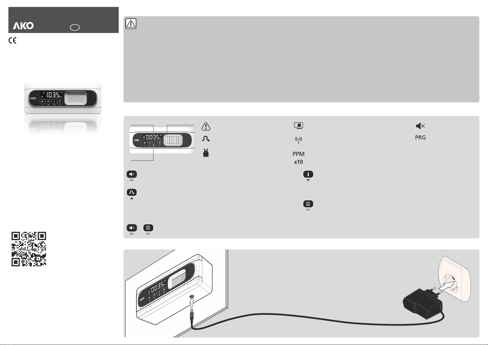
A
B
S/N:
Valid. code / IMEI:
Gas pre-alarm activated. Flashing together with the
gas concentration.
Gas alarm activated. Flashing together with the gas
concentration.
Initialisation process of the gas sensor. This may last
for up to 3 minutes.
Error or malfunction of the sensor. The Pre-Alarm relay
is activated, the transmitter emits 3 alert tones every 2
minutes and the icon flashes. Deactivate the ALM
power supply and activate it again. If after a few
seconds the error persists, please contact your
technical support centre.
The sensor has reached its maximum working
temperature.
The sensor has reached its minimum working
temperature.
Signing up to akonet.cloud
In order for the transmitter to be able to send operating data to akonet.cloud, it must be registered. To do this, go to
https://akonet.cloud (requires registration), click on “Add new device” and continue with one of these two methods:MAS
A.-Enter the serial number (S/N) and validation code / IMEI that appear on the tag and press “Search”.
B.-Capture the QR code that appears on the tag using the option (requires having a camera on your PC, tablet or QRC
mobile phone).
These data are found on the tag on the right hand side of the transmitter.
More information can be found in the akonet.cloud user guide at:
”http://help.ako.com/manuales/akonet-cloud”
To access akonet.cloud, enter this address in your browser (the use of Google Chrome is recommended):
https://akonet.cloud.
Before activating the device, make sure that there is enough reception at the installation location. Activated
devices may not be returned.
Forcing transmission
When the steps of the configuration wizard and the registration process are completed in akonet.cloud, you must force a
first transmission to verify the level of reception:
ŸPress and hold the ESC and SET keys for 3 seconds.
ŸAfter a moment, the display shows the quality of the NBIoT signal received:
The transmitter does not start transmitting data to akonet.cloud until the first transmission is forced.
Operation
Without alarms
The display shows the current gas concentration in ppm.
The transmitter regularly sends to the cloud (akonet.cloud) the gas concentration data and other operation information at specific intervals based on the akonet.cloud
parameter “continual log interval”.
Any change in the configuration of the transmitter or its operation (mode changes, errors, etc.) are sent to the cloud instantly.
Alarms
The transmitter emits an acoustic alarm, the alarm indicator flashes and activates the relays when certain gas concentration levels are exceeded.
There are two alarm levels depending on the concentration of gas detected: Pre-Alarm and Alarm. These have a factory setting of 1000 and 1400 PPM respectively. These
values comply with domestic and international regulations. However, please ensure that these values comply with current local regulations. In order to modify these values,
parameter AL1 should be configured to 1.
Activations and deactivations of pre-alarms and alarms are sent to the cloud instantly.
There are two possible methods for modifying the transmitter’s configuration:
-Through the device’s programming menu (refer to the user manual available at www.ako.com).
-At www.akonet.cloud, by accessing the device parameters menu.
Simplified declaration of conformity
AKO Electromecánica S.A.L. hereby declares that the radioelectric device types AKO-575xxxx (Gas transmitter with NBIoT communication) conform to the provisions set
forth by Directive 2014/53/EU.
The full text of the EU conformity declaration is available at the following internet address:
http://help.ako.com/manuales/declaracion-ue-de-conformidad
Technical specifications
AKO-575744NR
Power supply.................................................................................12 - 30 Vdc
Consumption Typical........................................................................75 mA
Maximum.................................................................125 mA
Pre-Alarm/Alarm relay ...........................................SPDT 30 Vdc, 2 A, cos j =1
Working ambient temperature..................................................-30 ºC to 50 ºC
Storage ambient temperature...................................................-30 ºC to 60 ºC
Range of maximum moisture permitted 0 95 without condensation.... - % HR ( )
Type of sensor.................................NDIR (Non-Dispersive Infrared Technology)
Display range.........................................................................0 - 2000 x1 ppm
Estimated working life..........................................................................7 years
Dimensions ..............................................202 mm (W) x 82 (H) x 55.5 mm (D)
Bands.........NBIoT (Narrow band) LTE Cat NB1 | B2, B3, B4, B8, B12, B13, B20
Band Frequency Rx Frequency Tx
2...........1930 MHz ~ 1990 MHz ........1850 MHz ~ 1910 MHz
3...........1805 MHz ~ 1880 MHz ........1710 MHz ~ 1785 MHz
4...........2110 MHz ~ 2155 MHz ........1710 MHz ~ 1755 MHz
8.............925 MHz ~ 960 MHz ............880 MHz ~ 915 MHz
12............729 MHz ~ 746 MHz ............699 MHz ~ 716 MHz
13............746 MHz ~ 756 MHz ............777 MHz ~ 787 MHz
20............791 MHz ~ 821 MHz ............832 MHz ~ 862 MHz
Maximum transmission power..........................................23.5 dBm conducted
Antenna ..............................................................................................Internal
External power supply
Working ambient temperature.....................................................0 ºC to 40 ºC
Input power supply range .........................................90 - 264 Vac / 47 - 63 Hz
Output voltage .....................................................................................15 Vdc
Peak output current ...................................................................................1 A