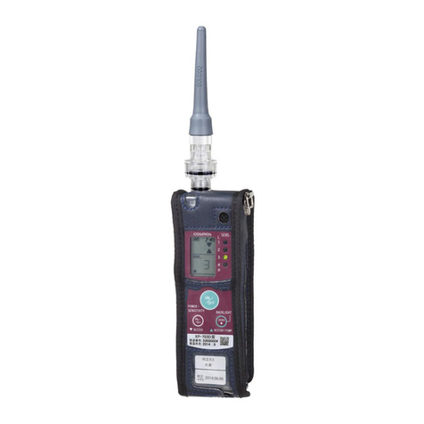
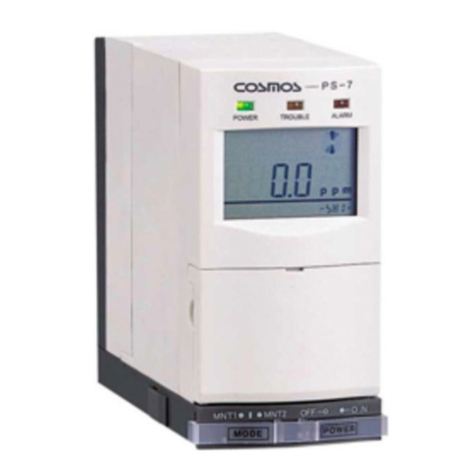
Cosmos XPS-7 User manual

●Store this Instruction manual in a convenient location, and consult it whenever
necessary.
●Operate the product only after reading and fully understanding the content of this
manual.
Instruction manual No.
XPS-7T(10)
Semiconductor Plant Gas Detector
XPS-7
Instruction Manual
●Store this Instruction manual in a convenient location, and consult it whenever
necessary.
●Operate the product only after reading and fully understanding the content of this
manual.
Instruction manual No.
XPS-7T(10)
Semiconductor Plant Gas Detector
XPS-7
Instruction Manual

1
1 Introduction
Thank you for purchasing the XPS-7 Semiconductor Plant Gas Detector. To ensure
correct operation, please read this operation manual carefully.
This product is designed to detect gas leaks in semiconductor manufacturing plants.
Sensor units (purchased separately) can be switched to detect a variety of gases.
Read and be sure you fully understand this manual even if you have used a Gas
Detector before.
Do not use the Gas Detector for any purpose other than that for which it was
intended. Do not attempt to use the product in a way other than that described in this
manual.
●Explanation of Symbols
This manual uses the following symbols. Their meanings must be understood and observed to
ensure safe operation of the Gas Detector.
DANGER
Indicates an impending hazardous situation that, if not avoided, could
result in serious injury or death.
WARNING
Indicates a potentially hazardous situation that, if not avoided, could re-
sult in serious injury or death.
CAUTION
Indicates a potentially hazardous situation that, if not avoided, could re-
sult in minor injury or physical damage.
Note Indicates operational advice and/or instructions.
●Observe the following precautions to ensure safe operation of the
Detector.
WARNING
:
The Gas Detector is not explosion-proof and must be used in a non-hazardous loca-
tion.
CAUTION
:The Gas Detector is not drip-proof and must be used in a location free from splashing
water.
CAUTION
:Do not allow the Gas Detector to be subjected to mechanical shock by being dropped
or struck.
CAUTION
:The Gas Detector must be turned ON in a clean-air environment. Otherwise, the per-
formance of the Detector may be impaired and normal detection may not be possible.
CAUTION
:The shelf life of the sensor unit is six months. Always check the sensor unit to be
sure its life has not expired prior to use. Normal detection may not be possible if an
expired sensor unit is installed.
1
TABLE OF CONTENTS
1 Introduction …………………………………………………………… 1
2 Contents of This Package …………………………………………… 2
3 Sensor Units …………………………………………………………… 2
4 Component Names and Functions ………………………………… 3
5 Operating Procedure ………………………………………………… 6
5-1 Inserting Batteries …………………………………………………………………… 6
5-2 Installing the Sensor Unit …………………………………………………………… 7
5-3 Turning the Gas Detector ON ……………………………………………………… 8
5-4 Detection ……………………………………………………………………………… 8
5-5 Ending Detection……………………………………………………………………… 8
6 Logger Function ……………………………………………………… 9
7 Replacing the Filter …………………………………………………… 10
8 Daily and Periodic Inspections ……………………………………… 11
9 Troubleshooting ……………………………………………………… 11
10 Consummable Parts and Options …………………………………… 11
11 Warranty ……………………………………………………………… 12
12 Specications ………………………………………………………… 13

1
1 Introduction
Thank you for purchasing the XPS-7 Semiconductor Plant Gas Detector. To ensure
correct operation, please read this operation manual carefully.
This product is designed to detect gas leaks in semiconductor manufacturing plants.
Sensor units (purchased separately) can be switched to detect a variety of gases.
Read and be sure you fully understand this manual even if you have used a Gas
Detector before.
Do not use the Gas Detector for any purpose other than that for which it was
intended. Do not attempt to use the product in a way other than that described in this
manual.
●Explanation of Symbols
This manual uses the following symbols. Their meanings must be understood and observed to
ensure safe operation of the Gas Detector.
DANGER
Indicates an impending hazardous situation that, if not avoided, could
result in serious injury or death.
WARNING
Indicates a potentially hazardous situation that, if not avoided, could re-
sult in serious injury or death.
CAUTION
Indicates a potentially hazardous situation that, if not avoided, could re-
sult in minor injury or physical damage.
Note Indicates operational advice and/or instructions.
●Observe the following precautions to ensure safe operation of the
Detector.
WARNING
:
The Gas Detector is not explosion-proof and must be used in a non-hazardous loca-
tion.
CAUTION
:The Gas Detector is not drip-proof and must be used in a location free from splashing
water.
CAUTION
:Do not allow the Gas Detector to be subjected to mechanical shock by being dropped
or struck.
CAUTION
:The Gas Detector must be turned ON in a clean-air environment. Otherwise, the per-
formance of the Detector may be impaired and normal detection may not be possible.
CAUTION
:The shelf life of the sensor unit is six months. Always check the sensor unit to be
sure its life has not expired prior to use. Normal detection may not be possible if an
expired sensor unit is installed.
1
TABLE OF CONTENTS
1 Introduction …………………………………………………………… 1
2 Contents of This Package …………………………………………… 2
3 Sensor Units …………………………………………………………… 2
4 Component Names and Functions ………………………………… 3
5 Operating Procedure ………………………………………………… 6
5-1 Inserting Batteries …………………………………………………………………… 6
5-2 Installing the Sensor Unit …………………………………………………………… 7
5-3 Turning the Gas Detector ON ……………………………………………………… 8
5-4 Detection ……………………………………………………………………………… 8
5-5 Ending Detection……………………………………………………………………… 8
6 Logger Function ……………………………………………………… 9
7 Replacing the Filter …………………………………………………… 10
8 Daily and Periodic Inspections ……………………………………… 11
9 Troubleshooting ……………………………………………………… 11
10 Consummable Parts and Options …………………………………… 11
11 Warranty ……………………………………………………………… 12
12 Specications ………………………………………………………… 13

2
3
4 Component Names and Functions
Name Function
①Power lamp (green) Flashes during the warm up period after the power is turned
ON and remains lit during operation.
②Trouble lamp (yellow) Flashes when an error occurs.
③Alarm lamp (red) Flashes when the detected gas concentration reaches the
alarm point.
④LCD display Indicates gas concentration and other information.
⑤Key switch cover Lightly pull the cover toward you to open it and access the key
switches.
⑥Buzzer speaker
⑦Gas inlet Sampled gas aspiration inlet. (6 dia.) Attaches to the gas inlet
tube.
⑧Gas outlet Exhaust outlet for sampled gas (6 dia.)
⑨Adapter connector Connects to the 100-VAC/6-VDC adapter plug.
⑩Battery cover Lift the snap lock and open the cover to insert batteries.
⑪Sensor cover Lift the snap lock and open the cover to insert the sensor unit.
⑫Sensor window Used to check the sensor unit that is installed.
⑬LED (red)
(Battery check)
Lit if the key switch cover is open with the Gas Detector turned
OFF, when batteries are inserted, or when batteries are low.
Main Unit
③
②
①
④ ⑤ ⑥
⑪
⑫
⑩
⑨
⑦
⑧
⑬
2
3
●
Observe the following precautions for the storage environment and method
of storing the Gas Detector.
WARNING
:Do not store the Gas Detector for long periods in locations with high temperatures or
high humidity. Otherwise, the performance of the Detector may be impaired.
CAUTION
:Do not subject the Gas Detector to sudden changes in temperature or humidity.
Otherwise, the performance of the Detector may be impaired.
CAUTION
:If the Gas Detector is not to be used for a long time, remove the batteries before
storing it.
2 Contents of This Package
The following components are included with the Gas Detector. Ensure that all components are
present before attempting to use the Detector.
□Gas Detector …………………………… 1 □Filters …………………………………… 2
□Shoulder strap ………………………… 1 □AA alkaline batteries…………………… 4
□Gas inlet tube…………………………… 1 □Inspection results……………………… 1
□Instruction manual……………………… 1
3 Sensor Units
Model Detected gases FS Alarm setting
1st level 2nd level
XDS-7NH NH3Ammonia 100 ppm 12 ppm 25 ppm
XDS-7SH SiH4Silane 25 ppm 2.5 ppm 5 ppm
XDS-7DC SiH2Cl2Dichlorosilane 25 ppm 2.5 ppm 5 ppm
XDS-7AH AsH3Arsine 250 ppb 25 ppb 50 ppb
XDS-7PH PH3Phosphine 1 ppm 0.15 ppm 0.3 ppm
XDS-7BH B2H6Diborane 500 ppb 50 ppb 100 ppb
XDS-7SE H2Se Hydrogen selenide 250 ppb 25 ppb 50 ppb
XDS7GH GeH4Germane 1 ppm 0.1 ppm 0.2 ppm
XDS-7CL Cl2Chlorine 5 ppm 0.25 ppm 0.5 ppm
XDS-7CF ClF3Chlorine triuoride 1 ppm 0.05 ppm 0.1 ppm
XDS-7HC HCl Hydrogen chloride 25 ppm 2.5 ppm 5 ppm
XDS-7HF HF Hydrogen uoride 10 ppm 1.5 ppm 3 ppm
XDS-7HB HBr Hydrogen bromide 10 ppm 1.5 ppm 3 ppm
XDS-7NO NO Nitrogen monoxide 100 ppm 12 ppm 25 ppm
XDS-7HS H2SHydrogen sulde 50 ppm 5 ppm 10 ppm
XDS-7CO CO Carbon monoxide 250 ppm 12.5 ppm 25 ppm
XDS-7DS Si2H6Disilane 25 ppm 2.5 ppm 5 ppm
XDS-7F2 F2Fluorine 5 ppm 0.5 ppm 1 ppm
XDS-7OZ O3Ozone 1 ppm 0.05 ppm 0.1 ppm
Contact an authorized representative of New Cosmos regarding other detectable gases not listed in the
table.

2
3
4 Component Names and Functions
Name Function
①Power lamp (green) Flashes during the warm up period after the power is turned
ON and remains lit during operation.
②Trouble lamp (yellow) Flashes when an error occurs.
③Alarm lamp (red) Flashes when the detected gas concentration reaches the
alarm point.
④LCD display Indicates gas concentration and other information.
⑤Key switch cover Lightly pull the cover toward you to open it and access the key
switches.
⑥Buzzer speaker
⑦Gas inlet Sampled gas aspiration inlet. (6 dia.) Attaches to the gas inlet
tube.
⑧Gas outlet Exhaust outlet for sampled gas (6 dia.)
⑨Adapter connector Connects to the 100-VAC/6-VDC adapter plug.
⑩Battery cover Lift the snap lock and open the cover to insert batteries.
⑪Sensor cover Lift the snap lock and open the cover to insert the sensor unit.
⑫Sensor window Used to check the sensor unit that is installed.
⑬LED (red)
(Battery check)
Lit if the key switch cover is open with the Gas Detector turned
OFF, when batteries are inserted, or when batteries are low.
Main Unit
③
②
①
④ ⑤ ⑥
⑪
⑫
⑩
⑨
⑦
⑧
⑬
2 3
●
Observe the following precautions for the storage environment and method
of storing the Gas Detector.
WARNING
:Do not store the Gas Detector for long periods in locations with high temperatures or
high humidity. Otherwise, the performance of the Detector may be impaired.
CAUTION
:Do not subject the Gas Detector to sudden changes in temperature or humidity.
Otherwise, the performance of the Detector may be impaired.
CAUTION
:If the Gas Detector is not to be used for a long time, remove the batteries before
storing it.
2 Contents of This Package
The following components are included with the Gas Detector. Ensure that all components are
present before attempting to use the Detector.
□Gas Detector …………………………… 1 □Filters …………………………………… 2
□Shoulder strap ………………………… 1 □AA alkaline batteries…………………… 4
□Gas inlet tube…………………………… 1 □Inspection results……………………… 1
□Instruction manual……………………… 1
3 Sensor Units
Model Detected gases FS Alarm setting
1st level 2nd level
XDS-7NH NH3Ammonia 100 ppm 12 ppm 25 ppm
XDS-7SH SiH4Silane 25 ppm 2.5 ppm 5 ppm
XDS-7DC SiH2Cl2Dichlorosilane 25 ppm 2.5 ppm 5 ppm
XDS-7AH AsH3Arsine 250 ppb 25 ppb 50 ppb
XDS-7PH PH3Phosphine 1 ppm 0.15 ppm 0.3 ppm
XDS-7BH B2H6Diborane 500 ppb 50 ppb 100 ppb
XDS-7SE H2Se Hydrogen selenide 250 ppb 25 ppb 50 ppb
XDS7GH GeH4Germane 1 ppm 0.1 ppm 0.2 ppm
XDS-7CL Cl2Chlorine 5 ppm 0.25 ppm 0.5 ppm
XDS-7CF ClF3Chlorine triuoride 1 ppm 0.05 ppm 0.1 ppm
XDS-7HC HCl Hydrogen chloride 25 ppm 2.5 ppm 5 ppm
XDS-7HF HF Hydrogen uoride 10 ppm 1.5 ppm 3 ppm
XDS-7HB HBr Hydrogen bromide 10 ppm 1.5 ppm 3 ppm
XDS-7NO NO Nitrogen monoxide 100 ppm 12 ppm 25 ppm
XDS-7HS H2SHydrogen sulde 50 ppm 5 ppm 10 ppm
XDS-7CO CO Carbon monoxide 250 ppm 12.5 ppm 25 ppm
XDS-7DS Si2H6Disilane 25 ppm 2.5 ppm 5 ppm
XDS-7F2 F2Fluorine 5 ppm 0.5 ppm 1 ppm
XDS-7OZ O3Ozone 1 ppm 0.05 ppm 0.1 ppm
Contact an authorized representative of New Cosmos regarding other detectable gases not listed in the
table.

4
5
Note Attaching and Removing the Gas Inlet Tube
●Attaching
Insert the tube into the coupling on the Gas Detector inlet and secure it in place
with the locking tab to seal the edge of the tube. After the tube is attached, make
sure that it will not pull out.
●Removing
Press in the release ring on the coupling and simultaneously pull out the gas inlet
tube.
Attaching Removing
Gas Inlet Tube
●Filter case
Contains the lter (FE-112).
●Gas inlet tube
One meter tube that connects to the
Gas Detector
●Gas sampling pipe
This is the gas inlet.
Tube adapter
Release ring
●Tube adapter
connects to the gas inlet on the
main unit
4
5
Name Function
①Power switch Press and hold to turn the Gas Detector ON and OFF.
②Alarm setting
indicator switch
Used to check the alarm settings. Press the switch repeatedly to
display the rst level alarm setting, second level alarm setting, and gas
concentration.
③Buzzer stop switch
④
Zero calibration switch
Press and hold to adjust the zero point automatically.
⑤CN jack Connects to the plug of a CA-7 Communications Adapter (option) used
for log data collection.
⑥
Special command switch
Used with the logger function.
⑦UP/DOWN switches Used to set the start time and other logger function settings.
Key Switches
LCD Display
●Log indicator
Lit when the log function is operating.
●Flow rate drop
Lit when the ow rate
drops.
●Gas concentration alarms
Lit when the detected gas concentration reaches the
alarm point.
●Sensor trouble
Lit when a sensor error occurs.
●Gas sampling ow rate
Normal: RUN, Error: STOP
●Gas concentration bar graph
Each bar is 5% of full scale. Bars lit all the
way to the right indicate full scale.
●Gas concentration
Indicates the gas concentration and unit.
●Battery indicator
Indicates the battery capacity.
Full
・
・
・
Exhausted (ashing)
① ② ③ ⑤
④
⑥
⑦

4
5
Note Attaching and Removing the Gas Inlet Tube
●Attaching
Insert the tube into the coupling on the Gas Detector inlet and secure it in place
with the locking tab to seal the edge of the tube. After the tube is attached, make
sure that it will not pull out.
●Removing
Press in the release ring on the coupling and simultaneously pull out the gas inlet
tube.
Attaching Removing
Gas Inlet Tube
●Filter case
Contains the lter (FE-112).
●Gas inlet tube
One meter tube that connects to the
Gas Detector
●Gas sampling pipe
This is the gas inlet.
Tube adapter
Release ring
●Tube adapter
connects to the gas inlet on the
main unit
4 5
Name Function
①Power switch Press and hold to turn the Gas Detector ON and OFF.
②Alarm setting
indicator switch
Used to check the alarm settings. Press the switch repeatedly to
display the rst level alarm setting, second level alarm setting, and gas
concentration.
③Buzzer stop switch
④
Zero calibration switch
Press and hold to adjust the zero point automatically.
⑤CN jack Connects to the plug of a CA-7 Communications Adapter (option) used
for log data collection.
⑥
Special command switch
Used with the logger function.
⑦UP/DOWN switches Used to set the start time and other logger function settings.
Key Switches
LCD Display
●Log indicator
Lit when the log function is operating.
●Flow rate drop
Lit when the ow rate
drops.
●Gas concentration alarms
Lit when the detected gas concentration reaches the
alarm point.
●Sensor trouble
Lit when a sensor error occurs.
●Gas sampling ow rate
Normal: RUN, Error: STOP
●Gas concentration bar graph
Each bar is 5% of full scale. Bars lit all the
way to the right indicate full scale.
●Gas concentration
Indicates the gas concentration and unit.
●Battery indicator
Indicates the battery capacity.
Full
・
・
・
Exhausted (ashing)
① ② ③ ⑤
④
⑥
⑦

6
7
5-2 Installing the Sensor Unit
①Lift the snap lock on the sensor cover and pull the cover toward you to open it.
②Note the position of the connector and the mounting slot as you push the sensor unit into
place.
③When the sensor unit is securely in place, close the sensor cover.
CAUTION
:●If the Gas Detector is used without a properly seated sensor unit, the Gas Detector
will not be air-tight and normal detection may not be possible. Make sure the unit is
properly seated.
●Use the sensor stocker model EC-7 (purchased separately) to supply power to
the sensor unit. A sensor unit that does not have power to it cannot detect gases
and may cause the sensor trouble indicator to light. A sensor unit installed in the
Gas Detector is powered even if the Gas Detector is turned OFF, as long as the
batteries are charged.
●When a sensor unit is replaced (shipped from the plant), install it in the Gas
Detector or connect it to the sensor stocker model EC-7 to supply a sufcient
amount of power to the new unit before turning ON the Gas Detector and using it
for the rst time.
●This Gas Detector uses XDS-7 sensor units and is not compatible with CDS-7,
COS-7, CHS-7 or any other sensor units.
●Sensor cover
Lift the snap lock and open the cover.
●Sensor
●Sensor
mounting slot
●Connector
6
7
5 Operating Procedure
Inspect the Gas Detector daily before using it. (Refer to page 13.) If the Detector is used without
rst performing the inspection, normal detection may not be possible and leaks may not be
detected.
CAUTION
:The Gas Detector must be turned ON in a clean-air environment. Otherwise, the
performance of the Detector may be impaired and normal detection may not be
possible.
5-1 Inserting Batteries
①Lift the snap lock on the battery cover and pull the cover toward you to open it.
②Insert the four AA alkaline batteries provided and make sure they are inserted according to
the polarity indicated in the battery compartment.
③Close the battery cover.
WARNING
:Replace all four batteries at the same time with fresh, new batteries.
Also make sure that the replacement batteries are all the same brand and type.
CAUTION
:Always replace the batteries in the following situations.
①The battery indicator shows a ashing box ( □) when the Gas Detector is ON.
(Refer to LCD display on page 5.)
②Nothing operates when the Gas Detector is ON.
③The battery check LED (red) is glowing very brightly (as bright as � above) when
the Gas Detector is OFF. (Refer to item � on page 4.)
●Battery
compartment
●Battery cover
Lift the snap lock and open the cover.

6
7
5-2 Installing the Sensor Unit
①Lift the snap lock on the sensor cover and pull the cover toward you to open it.
②Note the position of the connector and the mounting slot as you push the sensor unit into
place.
③When the sensor unit is securely in place, close the sensor cover.
CAUTION
:●If the Gas Detector is used without a properly seated sensor unit, the Gas Detector
will not be air-tight and normal detection may not be possible. Make sure the unit is
properly seated.
●Use the sensor stocker model EC-7 (purchased separately) to supply power to
the sensor unit. A sensor unit that does not have power to it cannot detect gases
and may cause the sensor trouble indicator to light. A sensor unit installed in the
Gas Detector is powered even if the Gas Detector is turned OFF, as long as the
batteries are charged.
●When a sensor unit is replaced (shipped from the plant), install it in the Gas
Detector or connect it to the sensor stocker model EC-7 to supply a sufcient
amount of power to the new unit before turning ON the Gas Detector and using it
for the rst time.
●This Gas Detector uses XDS-7 sensor units and is not compatible with CDS-7,
COS-7, CHS-7 or any other sensor units.
●Sensor cover
Lift the snap lock and open the cover.
●Sensor
●Sensor
mounting slot
●Connector
6 7
5 Operating Procedure
Inspect the Gas Detector daily before using it. (Refer to page 13.) If the Detector is used without
rst performing the inspection, normal detection may not be possible and leaks may not be
detected.
CAUTION
:The Gas Detector must be turned ON in a clean-air environment. Otherwise, the
performance of the Detector may be impaired and normal detection may not be
possible.
5-1 Inserting Batteries
①Lift the snap lock on the battery cover and pull the cover toward you to open it.
②Insert the four AA alkaline batteries provided and make sure they are inserted according to
the polarity indicated in the battery compartment.
③Close the battery cover.
WARNING
:Replace all four batteries at the same time with fresh, new batteries.
Also make sure that the replacement batteries are all the same brand and type.
CAUTION
:Always replace the batteries in the following situations.
①The battery indicator shows a ashing box ( □) when the Gas Detector is ON.
(Refer to LCD display on page 5.)
②Nothing operates when the Gas Detector is ON.
③The battery check LED (red) is glowing very brightly (as bright as � above) when
the Gas Detector is OFF. (Refer to item � on page 4.)
●Battery
compartment
●Battery cover
Lift the snap lock and open the cover.

6 Logger Function
The Gas Detector can record up to 22 hours of detection data. The recorded data can be written
to a personal computer using optional components that can be purchased separately. (See 10.
Consumable Parts and Options.)
Note
●Maximum gas concentration is recorded every 10 s after logging begins.
●New log data is stored in the Gas Detector by overwriting old data.
●The logger function terminates when the Gas Detector is turned OFF.
●Date settings are not supported.
●Refer to the XPS-7 Log Data Download Software in the XPS-7L Instruction Manual for the
procedure used to write log data to a personal computer.
①Press the DOWN switch (▼) once in RUN mode.
LOG will be displayed on the lower right corner of the LCD display
and the log start time can be entered.
②Press the SPECIAL COMMAND switch and the digit that
will change starts to flash. Use the UP/DOWN and SPECIAL
COMMAND switches to set the log start time.
Example: Enter the numbers shown in the display on the right to
set the log start time at 1:20 pm.
③After the time has been set, press and hold the ZERO switch.
MNT1
(maintenance mode 1) will be displayed on the lower left
corner of the LCD display and log recording will begin.
④To end log recording, press the BUZZER STOP switch while LOG
is displayed on the lower right corner of the LCD display. MNT1
will no longer be displayed and log recording will stop.
9
8
9
5-3 Turning the Gas Detector ON
①Press and hold the power switch. The buzzer sounds, the green power lamp ashes, and
self-diagnosis begins. The diagnostic procedure lasts about 30 seconds.
②When self-diagnosis is completed, zero adjustment is performed automatically, the green
power lamp lights, and the unit is ready to detect gas.
CAUTION
:●The Gas Detector must be turned ON in a clean-air environment. Do not allow the
Detector to draw in gas while it is warming up. Otherwise, zero adjustment will not
be performed properly and normal detection will not be possible.
●Wait at least 1 s before turning the Gas Detector back ON after a power failure.
5-4 Detection
Place the gas sampling pipe near the target detection area. When the unit detects gas, the
concentration of the detected gas is displayed. If the detected gas concentration level reaches the
alarm point, the alarm lamp lights and the buzzer sounds.
CAUTION
:Do not allow water or other liquids to enter the Gas Detector. Any liquid will cause the
Gas Detector to fail.
5-5 Ending Detection
When detection is completed, place the Gas Detector in a clean-air environment and allow it to
draw in clean air until the concentration indicator reads zero. Press and hold the power switch until
the Detector turns OFF.
CAUTION
:After an adsorbent gas has been detected, replace the lter with a new one
before attempting to detect another gas. Normal detection is not possible with a
contaminated lter.

6 Logger Function
The Gas Detector can record up to 22 hours of detection data. The recorded data can be written
to a personal computer using optional components that can be purchased separately. (See 10.
Consumable Parts and Options.)
Note
●Maximum gas concentration is recorded every 10 s after logging begins.
●New log data is stored in the Gas Detector by overwriting old data.
●The logger function terminates when the Gas Detector is turned OFF.
●Date settings are not supported.
●Refer to the XPS-7 Log Data Download Software in the XPS-7L Instruction Manual for the
procedure used to write log data to a personal computer.
①Press the DOWN switch (▼) once in RUN mode.
LOG will be displayed on the lower right corner of the LCD display
and the log start time can be entered.
②Press the SPECIAL COMMAND switch and the digit that
will change starts to flash. Use the UP/DOWN and SPECIAL
COMMAND switches to set the log start time.
Example: Enter the numbers shown in the display on the right to
set the log start time at 1:20 pm.
③After the time has been set, press and hold the ZERO switch.
MNT1
(maintenance mode 1) will be displayed on the lower left
corner of the LCD display and log recording will begin.
④To end log recording, press the BUZZER STOP switch while LOG
is displayed on the lower right corner of the LCD display. MNT1
will no longer be displayed and log recording will stop.
9
8 9
5-3 Turning the Gas Detector ON
①Press and hold the power switch. The buzzer sounds, the green power lamp ashes, and
self-diagnosis begins. The diagnostic procedure lasts about 30 seconds.
②When self-diagnosis is completed, zero adjustment is performed automatically, the green
power lamp lights, and the unit is ready to detect gas.
CAUTION
:●The Gas Detector must be turned ON in a clean-air environment. Do not allow the
Detector to draw in gas while it is warming up. Otherwise, zero adjustment will not
be performed properly and normal detection will not be possible.
●Wait at least 1 s before turning the Gas Detector back ON after a power failure.
5-4 Detection
Place the gas sampling pipe near the target detection area. When the unit detects gas, the
concentration of the detected gas is displayed. If the detected gas concentration level reaches the
alarm point, the alarm lamp lights and the buzzer sounds.
CAUTION
:Do not allow water or other liquids to enter the Gas Detector. Any liquid will cause the
Gas Detector to fail.
5-5 Ending Detection
When detection is completed, place the Gas Detector in a clean-air environment and allow it to
draw in clean air until the concentration indicator reads zero. Press and hold the power switch until
the Detector turns OFF.
CAUTION
:After an adsorbent gas has been detected, replace the lter with a new one
before attempting to detect another gas. Normal detection is not possible with a
contaminated lter.

8 Daily and Periodic Inspections
Daily Inspections
Checking the Gas Inlet Tube
Is the tube damaged? If so, replace it with a new one.
Checking the Filter
If the filter is dirty and discolored, replace it with a new one.
Periodic Inspections
To maintain accuracy, it is recommended that the Gas Detectorbe given periodic inspections
and adjustments at least once a year by an authorized representative of New Cosmos.
Replace the sensor unit every six months.
Note
Clean the Gas Detector by gently wiping it with a cloth dampened with water.
9 Troubleshooting
Symptom Possible cause Corrective action
Reference
The power does not come
ON even when the power
switch is pressed and
held.
Battery polarity is reversed. Correct the battery polarity. Page 6
The batteries are low. Replace the batteries.
The sensor unit is not installed. Install a sensor unit. Page 7
Abnormal drop in the flow
rate The filter is clogged. Replace the filter with a new one. Page 10
Sensor error
There is not enough power to
the sensor unit.
Make sure the sensor unit has
sufficient power when installing it. Page 7
The shelf life of the sensor unit
has expired.
Replace the sensor unit with a
new one. Page 7
10 Consumable Parts and Options
Part name Model number Remarks
Sensor unit XDS-7 □Contact an authorized representative of New
Cosmos regarding gases that can be detected.
Filters (10 per set) FE-112
AC adapter*Special adapter for 100-240V AC/6V DC.
Sensor Stocker*EC-7 Provides power for up to six sensor units at one
time.
Log data download software*XPS7L
Required to write log data to a personal computer.Communications adapter*CA-7
Serial crossover cable*KRS-L09-2K
11
*NotavailablefortheXPS-7withCEmarking.
10
11
Note
●Pressing the UP (▲) or DOWN (▼) switch repeatedly in RUN mode changes the display on
the bottom right corner of the LCD display as shown below. These are factory adjustments
that are not available for user application
7 Replacing the Filter
①Twist the filter holder with detection probe to open it.
② Use a pair of tweezers to remove the O ring and lter.
③ Insert a new lter and the O ring.
④ Reassemble the lter case.
●Filter
●O ring
●Filter holder
Twist the filter holder to
open it.
●Filter case
●Detection probe

8 Daily and Periodic Inspections
Daily Inspections
Checking the Gas Inlet Tube
Is the tube damaged? If so, replace it with a new one.
Checking the Filter
If the filter is dirty and discolored, replace it with a new one.
Periodic Inspections
To maintain accuracy, it is recommended that the Gas Detector be given periodic inspections
and adjustments at least once a year by an authorized representative of New Cosmos.
Replace the sensor unit every six months.
Note
Clean the Gas Detector by gently wiping it with a cloth dampened with water.
9 Troubleshooting
Symptom Possible cause Corrective action
Reference
The power does not come
ON even when the power
switch is pressed and
held.
Battery polarity is reversed. Correct the battery polarity. Page 6
The batteries are low. Replace the batteries.
The sensor unit is not installed. Install a sensor unit. Page 7
Abnormal drop in the flow
rate The filter is clogged. Replace the filter with a new one. Page 10
Sensor error
There is not enough power to
the sensor unit.
Make sure the sensor unit has
sufficient power when installing it. Page 7
The shelf life of the sensor unit
has expired.
Replace the sensor unit with a
new one. Page 7
10 Consumable Parts and Options
Part name Model number Remarks
Sensor unit XDS-7 □Contact an authorized representative of New
Cosmos regarding gases that can be detected.
Filters (10 per set) FE-112
AC adapter*Special adapter for 100-240V AC/6V DC.
Sensor Stocker EC-7 Provides power for up to six sensor units at one
time.
Log data download software*XPS7L
Required to write log data to a personal computer.Communications adapter*CA-7
Serial crossover cable*KRS-L09-2K
11
*NotavailablefortheXPS-7withCEmarking.
11

Detected gases Gases found in semiconductor manufacturing plants
Detection principle Electrochemical
Gas sampling method Extractive
Detection range As per specifications
Concentration display method LCD display
Detection accuracy
(See note 1.) ±10% of full scale
Response time
(See note 1.) Within 60 s (60% response)
Power supply Four AA alkaline batteries or AC adapter (optional item)
Battery operating time
(See note 2.)
Up to 12 hours of continuous operation (at 20℃with alkaline batteries and
no alarms)
Operating
temperature range 0 to 40℃
Dimensions W 62 x H 150 x D 128 mm (projected portions excluded)
Mass Approx. 1.3 kg
Approval (See note 3.) CE (EMC Directive, 2014/30/EU)
Note 1: The detection accuracy and response time were measured under identical detection
conditions.
Note 2: The operating time of the batteries depends on factors such as environmental
conditions, operating conditions, the storage time, and the manufacturer
Note 3: AC Adapter, EC-7 and Data Logger Software (optional items) are exempt from CE
marking. (see on page 11)
.
12 Specifications
13
12
13
11 Warranty
New Cosmos Electric Company Limited (New Cosmos) offers the following as the sole and
exclusive limited warranty available to Customer.
This warranty is in lieu of, and customer waives, all other warranties of any kind or nature,
expressed or implied, including without limitation, any warranty for merchantability or tness for a
particular purpose. The remedies set forth herein are exclusive.
New Cosmos warrants to the original purchaser and no other person or entity (customer) that
gas detection product supplied by New Cosmos shall be free from defects in materials and
workmanship for a period of one (1) year from the date of purchase. This warranty does not include
consumables, such as fuses, lters, etc. Certain other accessories not specically listed here may
have different warranty periods.
After examination of allegedly defective product return to New Cosmos, with freight prepaid, should
the product fail to conform to this warranty, customer's only remedy and New Cosmos's only
obligation shall be, at New Cosmos's sole option, replacement or repair of such non-conforming
product or refund of the original purchase price of the non-conforming product. In no event will New
Cosmos be liable for any other special, incidental or consequential damages or losses of any kind
whatsoever, including but not limited to, loss of anticipated prots and any other loss caused by
reason of non-operation of the product.
This warranty is valid only if the product is maintained and used in accordance with New Cosmos's
instructions and for recommendations. New Cosmos shall be released from all obligations under
this warranty in the event repairs or modications are made by persons other than its own or
authorized service personnel or if the warranty claim results from physical abuse or misuse of the
product.

Detected gases Gases found in semiconductor manufacturing plants
Detection principle Electrochemical
Gas sampling method Extractive
Detection range As per specifications
Concentration display method LCD display
Detection accuracy
(See note 1.) ±10% of full scale
Response time
(See note 1.) Within 60 s (60% response)
Power supply Four AA alkaline batteries or AC adapter (optional item)
Battery operating time
(See note 2.)
Up to 12 hours of continuous operation (at 20℃with alkaline batteries and
no alarms)
Operating
temperature range 0 to 40℃
Dimensions W 62 x H 150 x D 128 mm (projected portions excluded)
MassApprox. 1.3 kg
Approval (See note 3.) CE (EMC Directive, 2014/30/EU)
Note 1: The detection accuracy and response time were measured under identical detection
conditions.
Note 2: The operating time of the batteries depends on factors such as environmental
conditions, operating conditions, the storage time, and the manufacturer
Note 3: AC Adapterand Data Logger Software (optional items)are exempt from CE
marking. (see on page 11)
.
12 Specifications
13
13

Distributor: Manufacturer:
New Cosmos Electric Co., Ltd.
2-5-4 Mitsuya-naka Yodogawa-ku
Osaka 532-0036, Japan
URL:http://www.newcosmos-global.com
X PS-7 (09)●●.●●T
XPS-7T(10)2008.100
Other manuals for XPS-7
1
Table of contents
Other Cosmos Gas Detector manuals