Count Perfmaster Sprint User manual
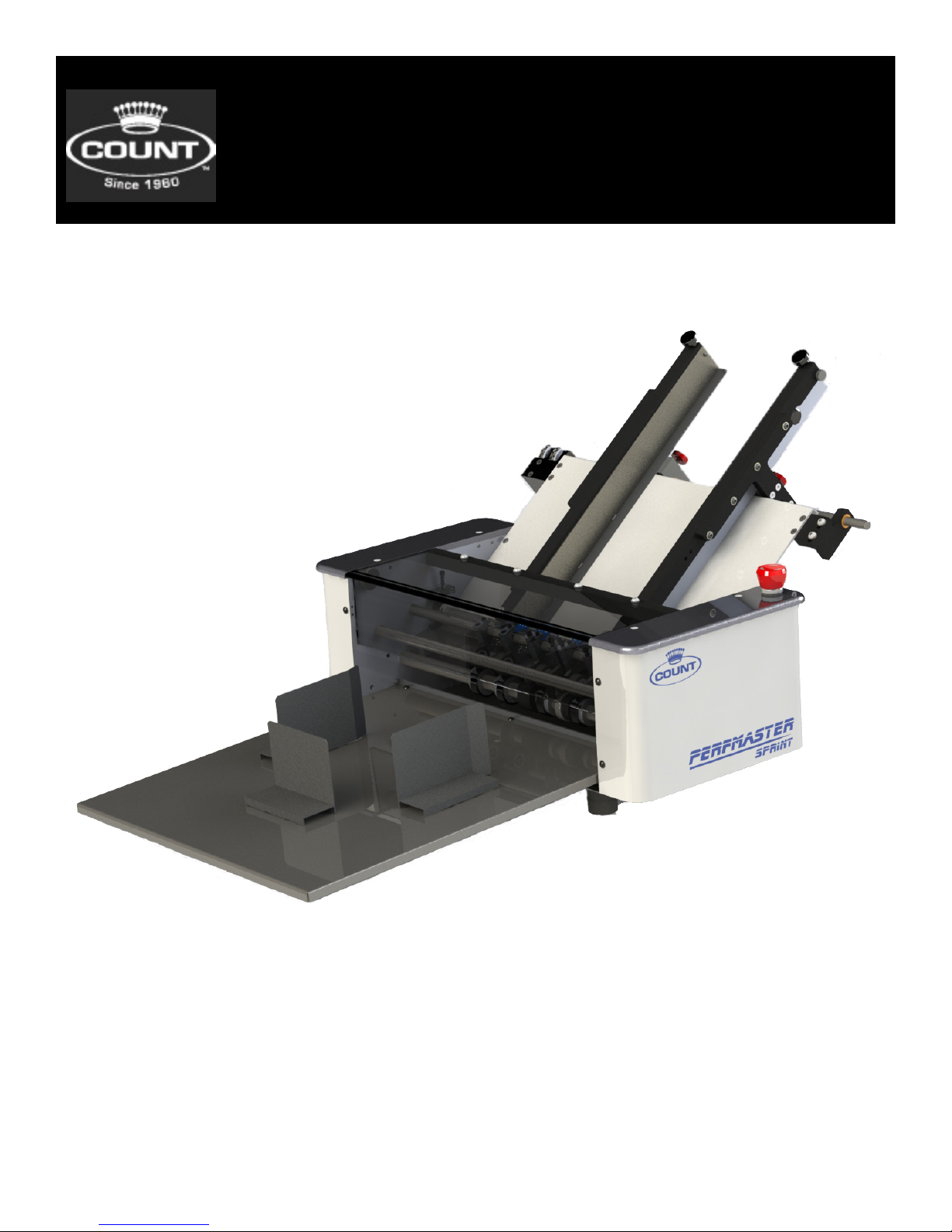
Perfmaster Sprint
01-2016

CONTENTS
CARE AND MAINTENANCE ___________________________________________ 1
SAFETY PROCEDURES ______________________________________________ 1
SPECIFICATIONS __________________________________________________ 1
COMPONENT IDENTIFICATION _______________________________________ 2
MACHINE CONTROLS _______________________________________________ 3
MAIN POWER_____________________________________________________ 3
SPEED CONTROL __________________________________________________ 3
EMERGENCY STOP _________________________________________________ 3
DELIVERY TRAY ___________________________________________________ 4
INSTALLING THE DELIVERY TRAY ................................................................................. 4
PAPER STOPS ____________________________________________________ 4
INSTALLING THE PAPER STOPS ..................................................................................... 4
FEED TABLE ______________________________________________________ 5
PARTS ............................................................................................................................. 5
FEED RAILS______________________________________________________ 6
ADJUSTING FEED RAILS................................................................................................. 6
SQUARING THE FEED RAILS........................................................................................... 6
PERFORATING & SCORING ASSEMBLIES________________________________ 7
REPLACING WORN BLADES............................................................................................ 7
PERFORATING & SCORING PARTS BREAKDOWN .......................................................... 8
TROUBLE SHOOTING _______________________________________________ 9

1
SPECIFICATIONS
Net Weight: 70 lbs
Overall Dimensions: 41”L x 30”W x 19”H
Boxed Dimensions: 32”L x 35”W x 25”H
Min. Sheet Size: 3” x 5”
Max. Sheet Size: 18” x 20”
Note: This machine is capable of handling many types of applications above and
beyond the standard specications. It is possible to feed quite a variety of
jobs, from 30” sheets to die cut stocks. However, the performance of the
machine on these special applications is directly related to the experience of
the operator.
SAFETY PROCEDURES
BEFORE USE
• Read Through the owner’s manual. Follow Instructions CAREFULLY.
DURING USE
• Keep ngers and hands away from score blades, perf blades, and rubber rollers.
BE ALERT! BE CAREFUL!
CARE AND MAINTENANCE
This is a precision machine. It is very important to keep it free of excessive dust, dirt
and foreign matter. We recommend that you keep the machine covered when not in
use.
BEARINGS/BUSHINGS
The bearings are sealed roller bearings and are designed to be self lubricating, however
dirt and dust can get into them causing clogging and dirt build up. It is recommended
to oil them daily under heavy use or monthly under light use. The Bushings are Bronze
and do require lubrication more frequently. Oil these once a week under heavy use.
RUBBER ROLLERS
These tend to harden when exposed, and in use, use “water to clean them before and
after each use. This will increase the life and require less replacement. “Do not use
Blanket Wash or Other Cleaners.”
REMOVABLE SCREWS
When these show signs of wear or stripping, replace as soon as possible. If these strip
or hollow out they can be costly to remove. If you do keep your machine clean and in
top condition, it will give you years of service.
2
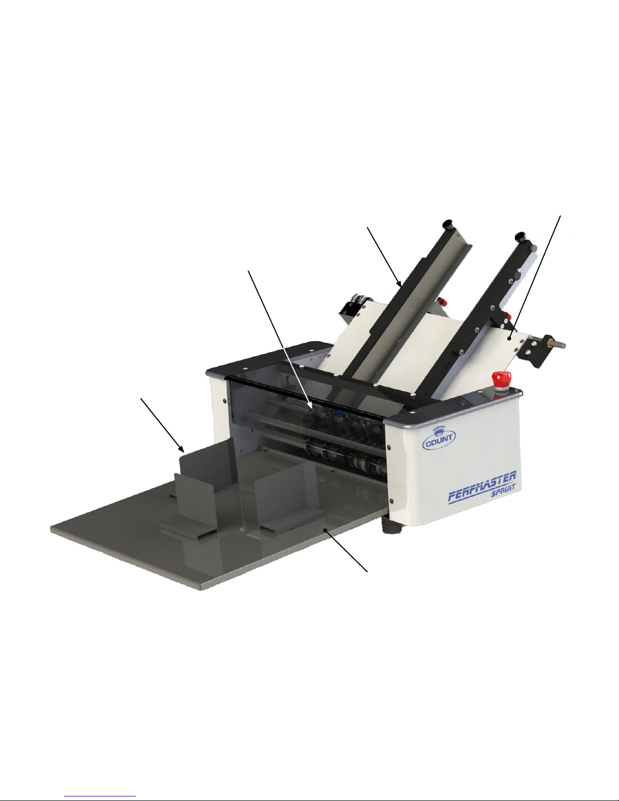
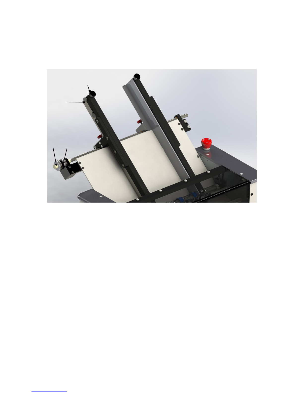
COMPONENT IDENTIFICATION
Perferating and Score Assemblies
Paper Stops
Feed Rail Assembly
Feed Table
Delivery Tray
3
MACHINE CONTROLS
There are three controls on this machine. The following section will explain the function of all
three controls.
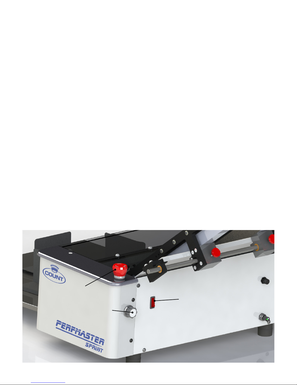
MAIN POWER
The main power switch is located on the back panel below the feed table and closest to the
operator side. A 3A (slow blow) fuse is also located on the back panel opposite to the power
switch.
SPEED CONTROL
Speed control is done with a knob on the top of operator side cover. This is a variable speed
machine. To start the motor turn the knob clockwise until you reach the desired speed. To stop
the motor on the machine turn the speed pot counter clockwise.
EMERGENCY STOP
SPEED CONTROL
MAIN POWER
EMERGENCY STOP
The emergency stop is intended to be activated in the case of an emergency to stop the
machine. Press down rmly on the emergency stop to engage the feature. To reset the machine
turn the know in the direction indicated on the knob. It is recommended to test this feature at
the begining of each use. If the machine continues to run after pressing down on the switch;
stop use of the machine, turn off main power, unplug the power cord from the wall outlet
and contact technical support for help resolving the issue. DO NOT OPERATE MACHINE IF
EMERGENCY STOP IS NOT WORKING.
4
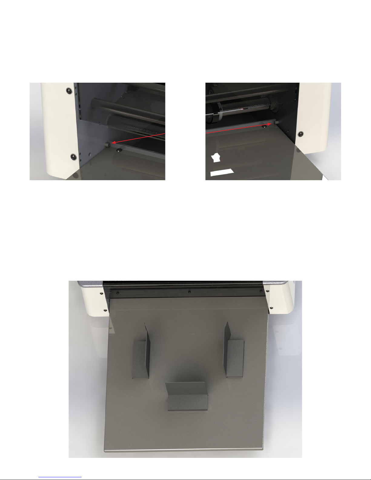
DELIVERY TRAY
INSTALLING THE DELIVERY TRAY
To install the delivery tray slide the tray under the dowel pins shown, with the angle facing
upward.
Dowel Pins
PAPER STOPS
INSTALLING THE PAPER STOPS
There are 3 different paper stops. 2 will have bends and 1 will be straight. The straight paper
stop is the rear or back paper stop. The other 2 are the right and left paper stops and should
be positioned as shown below. They hold there position using a magnet which makes it easy for
adjustment. The positions for the paper stops will change for each individual job. If the paper
stops are set to close, the paper will hit them as it exits the machine and will cause a paper jam.
If they are set too loose the paper will stack in an unorganized manner. Getting the position
correct is imperative to smooth operation of the machine.
5
FEED TABLE
12
3
4
PARTS
Item Part Description
Number Number
1. W-OF0645 Nut –Adjustment Feed
2. W-OF0645 Micro-Lateral Adjustment Lock
3. WRASAPP0005 Micro Skew Adj Knob
4. M-S0H0825 Feed Rail Lock Down
6
FEED RAILS
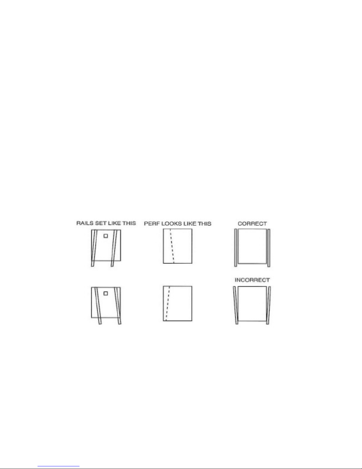
ADJUSTING FEED RAILS
The feed rails on this machine are designed to adjust easily in case of a problem with crooked
feeding. By loosening the feed rail alignment lock knobs you can move each rail independently
to square them to your stock. To maintain an accurate perf or score, it is important to get the
rails as aligned and snug to the sheet as possible without “squeezing” the sheet, as this will
create drag and cause the sheets to hang up in the rails.
To adjust this correctly, use one rail as your reference, the left (operator side). Place your
stock squarely against it then bring your right rail in and tighten, looking down it from the rear.
Adjust the rail with the skew adjustment knob so it is squared to the sheet. Then tighten the
lock knob. Set a sheet in the feeder, under the feed wheels, then run the machine. Check perf
by folding over and aligning the perfed edge.
Perf holes should line up within a blade’s width. If they do not line up, adjust rails accordingly,
moving your left rail rst and then adjusting the right rail to square the sheet. This may take a
few attempts, but this adjustment is important to produce quality perf and score jobs
FEED RAIL EXAMPLE
SQUARING THE FEED RAILS
The constant ne tuning of the rails will make it necessary to bring the rails back to true
“square”. To do this, take a sheet of 8 1/2 x 11” cover stock and place it in the feed table
against the operator side guide. Pressing the sheet against the rail, slide the rail over so that
the front edge of the stock lines up to the front edge of the feed table. Loosen the feed rail
adjustment lock knob, and use the skew adjustment knob to adjust the rail so that the sheet
is aligned with the left to right with the edge. Once this is done, slide the opposite side guide
into position and adjust it to the edge of the sheet. Your rails should now feed the sheet
perfectly aligned, providing a straight perf or score.

7
PERFORATING & SCORING ASSEMBLIES
REPLACING WORN BLADES
1. Loosen the socket head cap screw to remove pressure from the pressure adjust mounting
bracket.
2. Loosen the set screw and remove the pressure adjust mounting bracket.
Remove the button head cap screw that is retaining the score or perf blade.
3. Remove worn blade and replace with new blade. Attach new blade with existing button head
cap screw and washer.
4. Reinstall pressure adjust mounting bracket on machine.
5. Position upper and lower score/perf assemblies as desired, making sure to align the upper and
lower assembly.
6. Once the assemblies are aligned, tighten the set screw.
7. Reapply pressure to blade by tightening the socket head cap screw.
WRASAPP0129 WRASAPP0139

8
ITEM NO. PART NUMBER DESCRIPTION Q TY.
1 M-S003048 10-32 1-1/2 SOCKET SCREW 2
2W-OF2652 LOCKNUT PRESSURE BRACKET 2
3W-OF2040 CNC PERF GUARD 2
4 M-S0H0278 SCREW, 1/4-20X1/2” SOCKET SET HALF DOG 2
5 M-S007008 HEXNUT 10-32 LOCK-KEPNUT 2
6 M-S0H0456 WASHER, FLAT .200 X .438 X .031 2
7W-ASAPP0143 PERF BLADE ASSY 2
8 M-S003120 10-32 X 3/4 BHCS 2
9 M-S0H0215 SCREW 10-32X1/2 BHSC 2
10 W-ASAPP0131 SCORE BLADE ASSY 2
11 PRESSURE ADJUST MOUNTING BRACKET 2
PERFORATING & SCORING PARTS BREAKDOWN
Table of contents
Other Count Printer manuals


