Country Clipper PBSD User manual

OPERATOR’S MANUAL
ASSEMBLY OPERATION MAINTENANCE
PART# 629GR-001A
MANUAL#: Q0478
DESIGNED FOR THE DEFENDER & BOSS XL SERIES
Revision 4.0 - 6/18/2018
PROFESSIONAL BAGGING SYSTEM
MODEL# PBSD (49131502)

2
PROFESSIONAL BAGGING SYSTEM
TABLE OF CONTENTS
1-1 Introduction - - - - - - - - - - - - - - - - - - - - - - - - - 5
2-4 PTO Assembly Installation - - - - - - - - - - - - - - - 8
2-11 Top Assembly To
Warranty - - - - - - - - - - - - - - - - - - - - - - - - - - - - - 4
Safety - - - - - - - - - - - - - - - - - - - - - - - - - - - - - - 2
2-1 Preparation Of Mower - - - - - - - - - - - - - - - - - - 5-6
SECTION PAGE
2-2 Upper And Lower Rear Frame
2-7 Cam Assembly Adjustment - - - - - - - - - - - - - - - 10
2-3 PTO Mount Plate Component Installation- - - - - - 7
2-5 PTO Handle Installation - - - - - - - - - - - - - - - - - 8
II INSTALLATION FOR USE - - - - - - - - - - - - - - - - - - - - - 5
2-6 Belt Installation And Adjustment - - - - - - - - - - - - 9
2-10 Upper Frame Assembly Installation - - - - - - - - - 12
Upper Frame Assembly Installation - - - - - - - - - 12
1-2 Description - - - - - - - - - - - - - - - - - - - - - - - - - 5
2-12 Hinge Kit Assembly Installation- - - - - - - - - - - - 12
2-8 Blower Cone Installation - - - - - - - - - - - - - - - - - 10
I INTRODUCTION AND DESCRIPTION - - - - - - - - - - - - 5
2-9 Lower Mount Tube Installation - - - - - - - - - - - - - 11
Safety Alert Symbols- - - - - - - - - - - - - - - - - - - - - - 3
Bracket Installation - - - - - - - - - - - - - - - - - - - - 6
2-13 ROPS Pivot Bracket Installation - - - - - - - - - - - 13
2-14 Boot Plate Installation- - - - - - - - - - - - - - - - - - 14
2-15 Boot To Mower Deck Installation - - - - - - - - - - - 14
2-17 Upper Hose Installation - - - - - - - - - - - - - - - - 15
2-18 Lower Hose To Blower Cone Installation- - - - - - 15
2-19 Lower Hose To Boot Installation - - - - - - - - - - - 15
2-20 Impeller Blade Removal/Replacement - - - - - - - 16
2-21 Front Weight Installation - - - - - - - - - - - - - - - - 17
Exploded Part Views and Assemblies - - - - - - - - - 19-25
3-1 General Safety - - - - - - - - - - - - - - - - - - - - - - - 26
SECTION PAGE
3-2 Operation & Tips On Mowing - - - - - - - - - - - - - - 26
2-16 Length Of Hose Adjustment - - - - - - - - - - - - - - 15
III OPERATING INSTRUCTIONS - - - - - - - - - - - - - - - - - - 26
3-3 Disengagement Of The Blower - - - - - - - - - - - 26
3-4 Unloading The Collection System - - - - - - - - - - - 26
2-22 Installation and Removal Of Collection Bags - - - 18
IV MAINTENANCE - - - - - - - - - - - - - - - - - - - - - - - - - - - 26
Safety Decals - - - - - - - - - - - - - - - - - - - - - - - - - - 28
5-1 Parts And Service Information - - - - - - - - - - - - - 27
V PARTS AND SERVICE - - - - - - - - - - - - - - - - - - - - - - 27
4-1 Maintenance Checklist - - - - - - - - - - - - - - - - - - 26
4-2 Lubrication- - - - - - - - - - - - - - - - - - - - - - - - - - 27
Torque Specifications - - - - - - - - - - - - - - - - - - - - - 29
SAFETY
9. Mow across the face of slopes (not more than 10 degrees); never up and down the face.
removing clogs, removing or replacing hose, boot, blower cone, or performing any maintenance.
12. Wear hearing protection.
6. Do not attempt to operate your machine when not in the driver’s seat.
7. Always shut off blades and engine when emptying the container.
anyone who is not acquainted with the Safety Instructions to use your attachment.
3. Do not allow children to operate the machine. Do not allow adults to operate it without proper instruction.
you.
8. Stop machine, shut off deck attachment, set parking brake, shut off engine and remove ignition key before
1. Read the operator’s manual carefully and familiarize yourself with the proper use of your attachment. Do not allow
2. Know the controls and how to stop them quickly. READ THE OPERATOR’S MANUAL!
4. Be especially watchful of children and pets entering into the area while operating.
10. It is recommended that the container be emptied when half full while operating on slopes. Start mowing on slopes
11. Inspect your lawn and remove any foreign objects before mowing. Never deliberately run the mower across any
5. Keep your eyes and mind on your machine while mowing or operating your attachment. Don’t let others distract
foreign object.
when the container is empty.
13. Wear eye protection to prevent debris from getting into your eyes.
2017 (v1.0)

3
could result in death or serious bodily injury.
ALERT! YOUR SAFETY IS INVOLVED!”
Should be followed by the operator to avoid accidents. When
This symbol is used to call attention to safety precautions that
WARNING! To avoid serious injury, perform maintenance on the vacuum collector; ONLY AFTER
STOPPING THE MOWER’S ENGINE AND WAITING FOR ALL MOVING PARTS TO COME TO A
COMPLETE STOP. Set the parking brake. Always remove the ignition key before beginning maintenance.
WARNING! Do not work around the mower deck boot or the blower area until you are certain that the mower
blades and the blower impeller have stopped rotating.
and heed its advice. Failure to comply with safety precautions
The signal words DANGER, WARNING, and CAUTION are used on the equipment safety signs. These words
are intended to alert the viewer to the existence and the degree of hazard seriousness.
WARNING! For your own personal safety, ALWAYS mow ACROSS the face of slopes and
NEVER UP and DOWN the face. NEVER attempt to mow excessively steep slopes, and use
caution when turning on any slope.
This Safety Alert Symbol means: “ATTENTION! BECOME
Safety Signs
Safety Alert Symbol
you see this symbol, carefully read the message that follows
SAFETY
WARNING! NEVER operate the mower unless the discharge guard and either the deflector assembly or
the vacuum collector adapter are fastened securely in place.
DANGER
!
CAUTION
This signal word indicates a potentially hazardous situation which, if not
avoided, will result in death or serious injury.
It may also be used to alert against unsafe practices.
This signal word indicates a potentially hazardous situation which, if not
avoided, could result in death or serious injury.
It may also be used to alert against unsafe practices.
This signal word indicates a potentially hazardous situation which, if not
avoided, will result in minor or moderate injury.
White letters on RED
Black letters on ORANGE
Black letters on YELLOW
WARNING
!
!
!
2017 (v1.0)

4
COUNTRY CLIPPER LIMITED WARRANTY FOR NEW PRODUCTS
1. PRODUCT WARRANTY: Any part of the bagging system, which is defective in material or workmanship as
borne by the customer.
warranty adjustment can be authorized. At the time of requesting warranty adjustment, the purchaser must
Country Clipper extends the following warranties to the original purchaser of each new Country Clipper
C. ITEMS NOT COVERED BY COUNTRY CLIPPER WARRANTY.
bagging system subject to the following limitations:
All obligations of Country Clipper, under this warranty, shall be terminated if products are altered or modified in
ALL DEFECTIVE PARTS MUST BE RETURNED TO COUNTRY CLIPPER FOR
B. SECURING WARRANTY ADJUSTMENTS.
Engines, batteries, and gearboxes attached to Country Clipper products are covered under a separate
repaired or replaced, as Country Clipper elects, without charge if the defect appears within 90 days from the
Call Country Clipper for Return Authorization. Damaged or broken parts, other than engines or batteries, must
A. WHAT IS WARRANTED?
labor, if the defect appears within 12 months from the date of delivery of the product to the original purchaser.
INSPECTION TO DETERMINE VALIDITY OF WARRANTY CLAIMS. Freight and mailing will be
delivered to the purchaser will be repaired or replaced, as Country Clipper elects, without charge for parts or
2. PARTS REPLACED DURING WARRANTY: Any new Country Clipper bagging system which is furnished in
be returned to Country Clipper Division of Shivvers Mfg. Inc., 613 W. English, Corydon, IA, 50060 before any
performance of this warranty and is defective in material or workmanship as delivered to the purchaser will be
date of installation of such part or before the expiration of the original warranty period, whichever is later.
present evidence for date of delivery of the product. The purchaser shall pay any charge for the product to and
from Corydon, IA.
warranty by the respective manufacturer.
D. UNAPPROVED ALTERATION OR MODIFICATION.
ways not approved by Country Clipper.
caused by normal wear, accident, improper use or abuse of products. The cost of normal maintenance and
paid for by the purchaser.
The warranty covers only defective material and workmanship. It does not cover depreciation or damage
normal replacement of service items such as belts, cutting blades, hoses, etc., which are not defective shall be
F. NO REPRESENTATIONS ADDITIONAL WARRANTIES, DISCLAIMER.
E. ACCIDENTS AND NORMAL MAINTENANCE.
Neither Country Clipper nor any company affiliated with it makes any warranties, representations or promises
as to the quality of performance of its products other than those set forth herein. Except as described above,
Country Clipper makes no other warranties AND SPECIFICALLY DISCLAIMS ANY AND ALL
IMPLIED WARRANTIES OF FITNESS AND MERCHANTABILITY.
authority to make any representation or promise on behalf of Country Clipper or to modify the terms of this
1. NO SERVICE CENTER WARRANTY.
DATE OF ORIGINAL SALE ONLY.
Clipper bagging systems are set forth above. In no event will Country Clipper be liable for special incidental or
The only remedies the purchaser has in connection with the breach or performance of any warranty on Country
H. REMEDIED EXCLUSIVE.
The selling Service Center makes no warranty on his own on any item warranted by Country Clipper unless he
G. ANY MACHINE USED FOR RENTAL PURPOSES ARE GUARANTEED FOR 45 DAYS FROM
delivers to purchaser a separate written warranty certificate specifically warranting the item. The dealer has no
warranty in any way.
consequential damages.

5
1-1 Introduction
1-2 Description
The grass collection system is designed for turf
maintenance where there is a need to collect the grass
clippings as the mower cuts the turf. It is also used for
picking up leaves and twigs in pre-season and post-
season clean-up. The blower, mounted on the right side
of the unit, uses a belt and gearbox system from the
engine PTO shaft. Drive train protection comes through
belt slippage. The blower draws grass clippings from the
discharge area of the cutter deck back to the (3) - 4.0
cubic foot collection bags P#(G0003) at the rear portion
of the mower frame. The operator can engage the blower
with a push of the over-center linkage on the right side of
the unit. Once the bags are full with clippings, they can
be released to make for easy dumping.
NOTE: all references made to right, left, front, rear, top
or bottom are as viewed from the normal operator’s
position on the mower.
INSTALLATION FOR USE
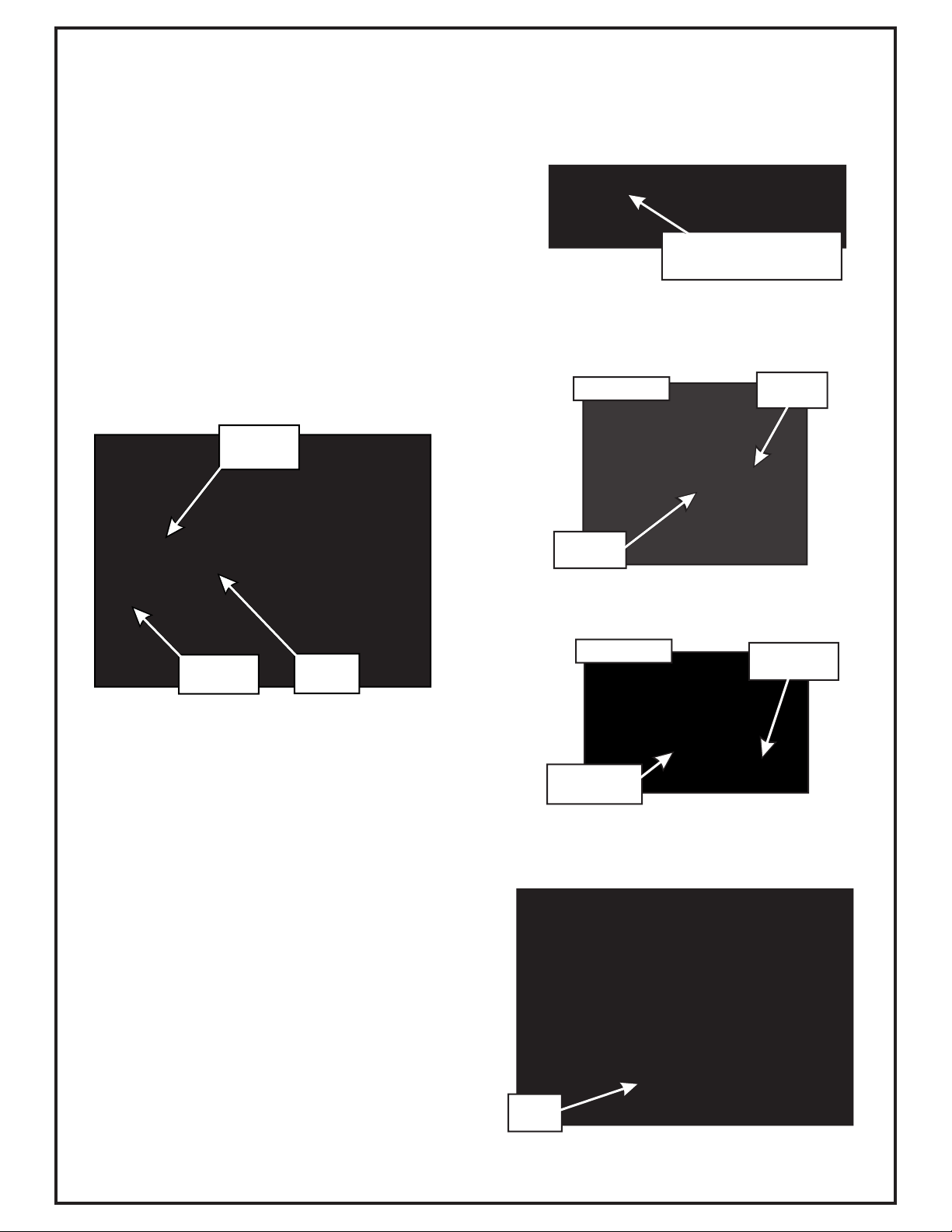
Remove deck drive belt from the clutch pulley (refer to
your Country Clipper operator’s manual). From the
underside of the engine, disconnect the wiring harness
attached to the electric clutch. Remove the bolt and
electric clutch from the mower. Refer to Figure 2-1a.
2-1 Preparation Of Mower
Your grass collection system has been designed to give
you a low maintenance, simple, and effective way to
collect the grass clippings from your mower. This manual
is provided to give you the necessary instructions to
properly mount and operate the collection system on
your mower. Please read this manual thoroughly.
Understand what each control is for and how to use it.
Observe all safety decal precautions on the machine and
noted throughout the manual.
Section II
Remove the D-drive spacer using an arbor press or
equivalent. On removal, adjacent bearing OUTER race
must be supported or bearing damage may occur. Refer
to Figure 2-1b.
SECTION I
INTRODUCTION AND DESCRIPTION
Use engine pulley assembly #25 P#(A1200), (1) 7/16”
lock washer P#(K0140), and 7/16”-20 x 4-1/2” hex bolt
P#(K0427).
Kawasaki FX801V / 27HP Kohler / 29HP Kohler
The added pulley will power the collection system. Note
that the center of the hub that is extended, should be
upward toward the engine (Figure 2-1d). Torque the bolt
to 55 ft./lbs. Please inspect that lock washer is
properly in place when the crankshaft bolt is fully
tightened.
Kawasaki FX1000V
The engine pulley assembly must be installed using an
arbor press or equivalent. Upon Installation, opposite
bearing inner race must be supported or bearing
damage may occur. Refer to Figure 2-1c.
Use engine pulley assembly #24 P#(A1176), (1) 7/16”
lock washer P#(K0140), and 7/16”-20 x 4-1/2” hex bolt
P#(K0427).
Electric Clutch
Figure 2-1d
Engine Pulley
Assembly
Hex Bolt Lock Washer
PRESS
Figure 2-1c
Engine Pulley Installation
Engine Pulley
Number Is
Stamped On
The Pulley
Bushing Here
Figure 2-1a
Remove Bolt Engine Bushing
PRESS
Figure 2-1b
Support Bearing
Outer Race
D-drive Spacer
D-drive Spacer Removal
Support Bearing
Inner Race

6
2-1 Preparation Of Mower Continued
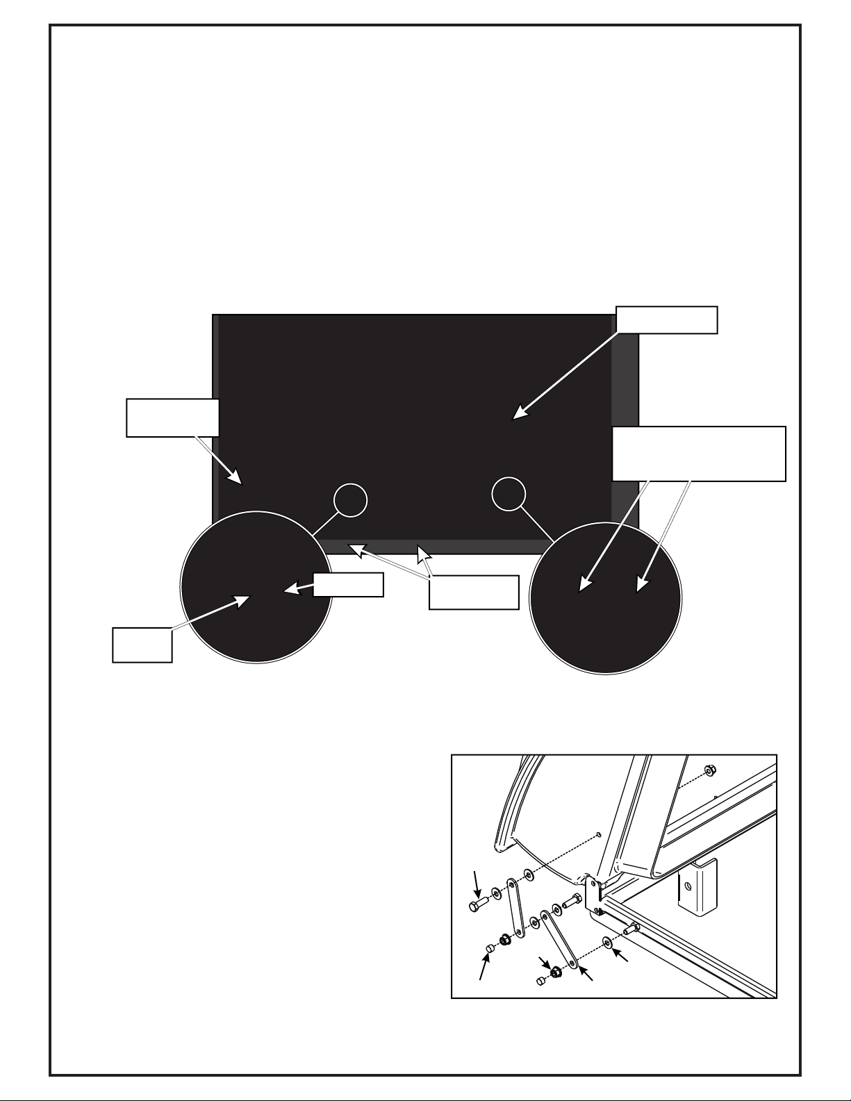
Remove the front step and mounting hardware from the
front caster assembly. Reference your Country Clipper
owner’s manual and Figure 2-1e. First, remove (2) existing top bolts 3/8”-16 x 1” FHCS
and (2) 3/8”-16 nyloc nuts that secure the top rear
engine guard bar. Secure the rear upper frame bracket
P#(B0853) with the hardware removed as shown in
Figure 2-2.
Next, remove (2) existing bottom bolts 3/8”-16 x 1”
FHCS and (2) 3/8”-16 nyloc nuts that secure the bottom
rear engine guard bar. Secure the rear lower frame
bracket P#(B0851) with the hardware removed as
shown in Figure 2-2.
2-2 Upper And Lower Rear Frame
Bracket Installation
Remove
Front Step
Caster
Assembly
Figure 2-1e
6
Figure 2-2
Rear Upper
Frame Bracket
Rear Lower
Frame Bracket
(4) Existing
3/8”-16 x 1” FHCS
(4) Existing
3/8”-16 Nyloc Nuts
Top Rear
Engine
Guard Bar
Bottom Rear
Engine
Guard Bar
Rear Engine
Guard

7
Figure 2-3a
(2) Existing
1/2”-13 x 2”
FHCS
Left PTO
Mount Plate
(1) Existing
1/2”-13
Nyloc Nuts
Top Rear
Engine Guard
Bar
Bottom Rear
Engine Guard
Bar
(1) Existing
1/2”-13
Nyloc Nuts
1/2”-13 nyloc nuts from the top and bottom rear engine
guard bars (shown in Figure 2-3a). Secure the Left PTO
mount plate P#(B0852) using the existing hardware.
Remove the (2) existing 1/2”-13 x 2” FHCS and (2)
2-3 PTO Mount Plate Components
Installation
Secure the right PTO mount plate P#(B0854) to the left
PTO mount plate, using (2) 3/8”-16 x 1” HHCS
P#(K1191) and (2) 3/8”-16 nylon flange locknuts
P#(K2038). Do not tighten the hardware completely.
Insert the PTO stop plate P#(B0736) between the left
and right PTO mount plates and secure using (4) 1/4”-
20 x 3/4” HHCS P#(K1222) and (4) 1/4”-20 nylon flange
locknuts P#(K2014). Tighten all PTO component
hardware at this time. Refer to Figure 2-3b.
Figure 2-3b
PTO Stop
Plate
Right PTO
Mount Plate
(2) 1/4”-20 x 3/4”
Hex Bolts
(4) 1/4”-20
Locknuts
Left PTO
Mount Plate
(2) 3/8”-16
Locknuts
(1) 3/8”-16 x 1”
Hex Bolts
(2) 1/4”-20 x 3/4”
Hex Bolts
(1) 3/8”-16 x 1”
Hex Bolts

8
2-4 PTO Assembly Installation
To mount the PTO assembly, insert the pivot rod on the
PTO assembly P#(A1950) into the mounting slots
located on the left & right PTO mount plates (Figure 2-
4a). Tilt the PTO assembly upward and insert the PTO
mount pin P#(B0274) through the hole in the top of the
right PTO mount plate assembly. Secure the PTO mount
pin using 1/8” x 2-3/8” hair pin clip P#(K0086) as shown
in Figure 2-4b.
Note: Remove the gearbox pulley guard in preparation
for the belt installation. Refer to Figure 2-4a.
2-5 PTO Handle Installation
Attach the PTO handle P#(A1142) to the PTO assembly
using (3) 1/4”-20 x 3/4” HHCS P#(K1222) and (3) 1/4”-
20 nylon flange locknuts P#(K2014). Attach the handle
grip P#(J0522) to the PTO handle. Refer to Figure 2-5.
NOTE: The PTO Handle can be adjusted after
performing Step 2-8 to achieve proper belt adjustment.
To adjust the handle, remove (3) 1/4”-20 x 3/4” HHCS
P#(K1222) and (3) 1/4”-20 nylon flange locknuts
P#(K2014), rotate handle until positioned in the desired
location (while aligning holes) and reattach. The bolts
should be kept approximately 120 degrees apart to
ensure proper fastening.
Figure 2-4b
PTO
Mount Pin
Hair Pin
Clip
Install PTO
Handle Here
Figure 2-4a
Figure 2-5
Mounting
Slot
PTO
Assembly
Pivot
Rod PTO Handle
Handle Grip
(3) 1/4”-20 x 3/4” HHCS
(3) 1/4”-20 Nylon
Flange Locknut
Remove
Gear Box
Pulley Guard

9
2-6 Belt Installation and Adjustment
PTO MODELS ONLY
Loosen the (4) bolts P#(K1191), (2) on each side, that
secure the gear box assembly to the PTO assembly
P#(A1950) (Figure 2-6a and 2-6b).
Loosen the adjustment bolt P#(K0348) until the gear box
assembly is at its far left adjustment (the gear box is
moved toward the mower’s engine pulley). Refer to
Figure 2-6c.
To tension the drive belt, turn the adjustment bolt
clockwise (Figure 2-6e) until there is 1” of deflection, with
10-11 lbs. of pressure, at the center of the belt between
the engine pulley and the gear box pulley.
Connect the belt A57K P#(M0256) from the engine
pulley to the lower gear box pulley (Figure 2-6d).
Once the correct tension of the belt is achieved, tighten
the (4) bolts that secure the gear box assembly. Refer to
Figures 2-6f and 2-6g. Replace the belt guard and
hardware that was removed in Section 4.2-
Loosen Bolts
Figure 2-6a
Figure 2-6b
Loosen Bolts
Figure 2-6c
Loosen The
Adjustment Bolt
Slide Gear Box
Towards The
Engine Pulley
Connect Belt
To Both Pulleys
Figure 2-6d
Figure 2-6e
Figure 2-6f
Figure 2-6g
Tighten Bolts
Tighten Bolts
Tighten The Adjustment
Bolt To Tension The Belt
10
2-7 Cam Assembly Adjustment
The cam assembly P#(A0422), which controls the
blower belt tension, comes from the factory pre-adjusted.
If the belt is too tight or becomes too loose, remove the
hair pin clip P#(K0130) from the belt tension rod
P#(K0326) and pull the “L” end of the rod out of it’s hole
in the cam assembly.
The tension rod may then be screwed out to tighten the
belt or screwed in to loosen the belt. Replace the “L” end
into the top hole in the cam and replace the hair pin clip.
Adjust the cam stop bolt P#(K1159) to allow the cam to
rotate slightly over center when the blower is engaged
(Figure 2-7).
Now partially thread (1) bolt into each of the two
threaded bosses located on the blower housing. Place
blower cone so the two tabs line up with the bolts and
tighten completely as shown in Figure 2-8b.
Once the (2) bolts are tight, tighten the jam nuts against
the threaded boss as shown in Figure 2-8c.
Refer to Figure 2-8d for proper blower cone installation
reference.
2-8 Blower Cone Installation
Thread (1) 5/16”-18 jam nut P#(K0120) onto each end of
(2) 5/16”-18 x 2-1/2” HHCS P#(K0125) as shown in
Figure 2-8a.
Figure 2-7
Cam
Assembly
Cam Stop
Bolt
Tension
Rod
Figure 2-8a
Thread (1) Jam Nut
Onto Each 5/16”-18 Bolt
Figure 2-8b
Threaded
Boss
Blower
Cone Tab
Figure 2-8c (1st) Tighten
Bolt
(2nd) Tighten
Jam Nut
Figure 2-8d
Blower
Cone

11
The bottom edge of the lower mount tubes should be flush with the bottom flange of the rear lower frame bracket.
Refer to Figure 2-9.
Secure the (2) lower mount tubes P#(B0640) to the rear lower and upper frame brackets using (2) 5/16”-18 x 2-1/4” u-
bolts P#(K1098) and (4) 5/16”-18 nylon flange locknuts P#(K2516) PER TUBE.
2-9 Lower Mount Tube Installation
Figure 2-9
Lower Mount
Tubes
(4) 5/16”-18
Locknuts
PER Tube
(2) 5/16”-18
U-Bolts
PER Tube
Rear Upper
Frame Bracket
Rear Lower
Frame Bracket
12
Lift the upper frame assembly P#(A1058) and lower the
upper frame assembly onto the two lower mount tubes.
Secure the top assembly to the lower mount tubes using
(2) clevis pins P#(K0133) and (2) hair pin clips
P#(K0088). Refer to Figure 2-10.
2-10 Upper Frame Assembly
Installation
NOTE: During this step, it is suggested that two people
install the upper frame to the lower mount tube.
Assemble the hinge kit as shown in Figure 2-12, using
(2) 5/16”-18 x 1” HHCS P#(K1154), (3) 5/16”-18 nylon
flange locknuts P#(K2516), (5) 1/4” flat washers
P#(K0037) and (2) swing arm brackets P#(ZT-0004).
Place (1) vinyl cap P#(J0289) on the end of the hex bolts
as shown in Figure 2-12. Leave the nuts loose enough to
allow fluid movement of the top when opening and
closing. When opened, the top should rest on the middle
joint of the hinge allowing it to remain up.
2-12 Hinge Kit Assembly Installation
2-11 Top Assembly To Upper Frame
Assembly Installation
Position the top assembly P#(A1190) above the upper
frame assembly as shown in Figure 2-10. Fasten the top
assembly to the upper frame assembly using (2) 5/16”-
18 x 2-1/2” HHCS P#(K0125) and (2) 5/16”-18 nylon
flange locknuts P#(K2516). Leave the locknuts slightly
loose, to allow the top assembly to open and close
easily.
Figure 2-10
Upper Frame
Assembly
Top Assembly
Lower
Mount Tubes
Clevis Pin
Hair Pin
Clip
(1) 5/16-18 x 2-1/2” HHCS
(1) 5/16”-18 Nylon Flange
Locknut
ZT-0004
K2516
K0037
K1154
J0289
Figure 2-12

13
To allow the ROPS to fold down without hitting the
bagger top, insert a total of (4) B0872 - ROPS Pivot
Brackets, (2) per side with arrow aligned as shown in
Figure 2-13a. When folding the ROPS is desired, pin the
ROPS as shown in Figure 2-13b. This will prevent
damage to the bagger top while mowing or transporting.
2-13 ROPS Pivot Bracket Installation
Figure 2-13a
Figure 2-13a
B0872 - ROPS Pivot Bracket

14
Secure the boot plate P#(B0820) to the aluminum boot
P#(E1902) using (2) 3/8”-16 x 1” carriage bolts
P#(K1182) and (2) 3/8”-16 nylon flange locknuts
P#(K2038). Insert the carriage bolts from the inside of
the boot so the threads are on the top of the boot. This
will prevent grass clippings from collecting on the
threads. Leave the hardware loose until the boot plate
has been attached to the mower deck. Refer to Figure 2
-14a and 2-14b for reference.
2-14 Boot Plate Installation
Remove the hardware from the grass deflector and
insert (1) boot rod P#(B4331) into the grass deflector
mounting holes as shown in Figure 2-13a. Secure the
boot rod using (1) hair pin clip P#(K0099). With the
carriage bolts from Section 2-14a still loose, adjust the
position of the boot so that there is no gap between the
mower deck and the boot. Tighten the hardware at this
time.
2-15 Boot To Mower Deck Installation
Boot Rod
(2) 3/8”-16 x 1”
Carriage Bolts
(2) 3/8”-16
Locknuts
Boot Plate
Aluminum
Boot
Hair Pin
Clip
Figure 2-14a
Figure 2-14b
Defender
Mounting Holes

15
2-18 Lower Hose To Blower Cone
Installation
(away from yourself) approximately 1” to aid in retaining
clamp to secure the hose to the boot (Figure 2-19). Tip:
2-19 Lower Hose To Boot Installation
Slide a hose clamp P#(J0080) over both ends of
over the circular end of the boot. Use the lower hose
Note: For maximum collection system performance,
adjust the hose lengths (Step 2-16) to achieve the
smoothest transition between components. Avoid any
sharp bends in the upper and lower hoses.
Take the unattached end of the lower hose and slide it
boot to mower deck.
the lower hose. Then proceed to slide the lower hose
onto the blower cone. Tighten the hose clamp. Refer to
Figure 2-19.
Before securing clamp rotate hose counter-clockwise
hoses until you have tried to fit them on your machine.
Remember that the hoses need to be long enough to
allow for the opening and closing of the collection
system, PTO blower housing engagement, as well as
allowing ample clamping surface between each
component.
The hoses in steps 2-17 and 2-18 must be cut to fit your
Slide a pre-assembled hose clamp P#(J0060) onto both
2-16 Length Of Hose Adjustment
ends of the 6” upper hose (Figure 2-19). Slide one
end of the 6” hose onto the plastic inlet P#(V0025).
Make sure there is about a two-inch overlap between the
hose end and the plastic inlet. Proceed to slide the
opposite end of the 6” hose onto the outlet of the blower
assembly. See (Figure 2-19) for details. Make sure both
ends of the hose are clearly attached to the inlet and the
blower assembly inlet. Tighten the hose clamps.
machine. Follow steps 2-17 and 2-18. Do not cut the
2-17 Upper Hose Installation
Figure 2-19
Inlet
Hose
Clamps
Hose
Clamps
Upper
Hose
Boot
Lower
Hose
Blower
Outlet Blower
Cone

16
3
2
4
5
1
3
5
6
7
8
9
10
12
13
11
14
9Taper-Lock Bushing
Enlarged View
1 - Try carefully hitting the base of the impeller blade
(#1), between each vein (#12), with a rubber mallet to
loosen the taper-lock bushing hold.
2 - Spray break-free lubricant into the surrounding areas
of the taper-lock bushing (#9) and repeat Tip 1.
To Replace: First, place the impeller blade (#1) over the
drive shaft (#13). Next, slide the taper-lock bushing (#9)
on to the drive shaft and into the impeller blade, aligning
the non-threaded holes (#14) of the taper-lock bushing
to the threaded holes of the impeller blade. Then, fasten
by using two 1/4”-20 x 1” HHCS (#10), one spacer
bushing (#8) one taper lock bushing washer (#7), and
one 3/8”-16 x 1-1/2” HHCS (#6). Torque all bolts to the
specifications located in the chart towards the back of
this manual. Last, rotate the impeller blade to ensure
that the blade is clear of contact on all sides of the
blower housing.
Tips on removing impeller blade;
2-20 Impeller Blade
Removal/Replacement
To gain impeller blade (#1) access, first remove the
blower cone (#2) from the blower housing, located on
the PTO assembly P#(A1821), by removing two blower
cone bolts and nuts (#3). Next, remove the blower
housing front (#4) by removing seven bolts and nuts (#5)
around the outer housing edge. Refer to Figure 2-21.
To Remove: First, remove one 3/8”-16 x 1-1/2” HHCS
P#(K1211) (#6), one taper-lock bushing washer
P#(K0278) (#7) and one spacer bushing P#(S3242) (#8)
from the taper-lock bushing (#9). See Figure 2-20. Next,
remove two 1/4”-20 x 1” HHCS (#10) and place them
into the threaded holes (#11) of the taper-lock bushing
P#(S4302). Last, gradually thread each bolt evenly into
the taper-lock bushing, forcing the blade to break-away
from the taper-lock bushing.
Figure 2-20

17
Align the (4) holes of the Weight Bracket Clamp (Item#2) to the holes in the Dual Weight Bracket Base (Item#1).
Loosely fasten the Weight Bracket Clamp (Item#2) to the Weight Bracket Base (Item#1) using (4) 5/16"-18 x 3" Bolts
(Item#4) & (4) 5/16"-18 Ny-Flange Lock Nuts (Item#5).
Repeat on additional caster. Refer to the Figure Below.
Insert (1) Weight (Item#3) Into the Weight Bracket Base (Item#2) & align the holes of the Weight w/ the holes of the
Weight Bracket Base (Item#2). Fasten the Weight (Item#1) to the Weight Bracket Base Using (1) Clevis Pin (Item#6)
& (1) Hair Pin Clip (Item#7) per weight.
Weight Kit Installation
Position the Dual Weight Bracket Base (Item#1) under the caster tubing w/ opening towards caster fork. Next, position
the Weight Bracket Clamp (Item#2) on top of caster tubing w/ opening towards caster fork.
Position the Weight Bracket Base and the Weight Bracket Clamp assembly along the caster tubing to prevent
interference from caster forks or any other objects. Tighten the fasteners in an 'X’ pattern until assembly is firmly
clamped to caster tubing. Do not over tighten which may result in bending Weight Bracket Clamps (Item#3).
1
2
5
3
4
6
7
Figure A
Item # Part # Desc. Qty.
1 B1014 Dual Weight Bracket / Base 1
2 B1015 Weight Bracket / Clamp 1
3 Y0025 28 lb. Suitcase Weight 2
4 K1472 HHCS 5/16"-18 x 3" GR5 4
5 K2516 Ny-Flange Lock Nut 5/16"-18 4
6 K1473 Clevis Pin 1/2" x 3" 2
7 K1478 Hair Pin Cotter / Double Loop 2

18
To empty the bag, first unlatch and lift top, next remove
the bag and bag ring by sliding rearward, then grasp the
loop on the bottom of the bag, and last turn it upside
down to empty the collected debris (Figure 2-22d).
Repeat for the other bags. Reinstall all bags, line with
plastic bags if desired, close the plastic top and reattach
the draw latches.
Plastic lawn and leaf bags, 33 gallon size, may be used
inside the cloth bags. Be sure to leave enough plastic
bag hanging over the frame so the plastic bags can be
twist tied before emptying (Figure 2-22e).
2-23 Installation/Removal Of
Collection Bags
To prevent bag wear, install (2) red plastic end caps
P#(J0274), as shown in Figure 2-22a, on each bag ring
before installing bags.
IMPORTANT!
To install the bag onto the bag ring, place the seam
openings of the bag onto the bag ring openings and turn
the bag one full turn (360 ) so the plastic end caps are
located opposite to the opening in the bag (Figure 2-
22b). Do this for each of three bags.
Install the completed assemblies onto the support frame
and close the plastic top. Fasten both draw-latches to
hold the plastic top closed (Figure 2-22c).
Figure 2-22d
Figure 2-22e
Grasp Bag
Here
Plastic Bag
Cloth Bag
Figure 2-22a
Figure 2-22c
Figure 2-22b
Red Plastic
End Caps
Bag Ring
Bag
Bag Opening
Bag Ring End
Caps Opposite
of Bag Opening
Plastic Top
Fasten Draw
-Latch Here &
Opposite Side
For Proper Unit
Transportation
Completed Bag
Installed

19

20
2
9
4
6
7
10
3
5
8
11
18
17
14
16
15
1
13
12
Item # Doc # Title Qty
1 V0022 PRO 3 BAGGER TOP 1
2 B0676 Hinge Stop Pl. 1
3 K0114 BLACK PLASTIC RIVET 14
4 C0069 DUST GUARD BRACE 1
5 K1030 1/4"-20 x 1-1/4" CARRIAGE BOLT 2
6 J4009 SHORT RUBBER STRAP W/ S HOOK 2
7 K0037 1/4" FLAT WASHER .75 OD x .314 ID x .060 T 2
8 K1128 1/4"-20 NYLOC NUT 2
9 C0026 GRASS DEFLECTOR 1
10 K0062 3/16" x 1-1/2" FENDER WASHER, Z 4
11 K1265 BLACK PANEL RETAINER 3
12 V1120 Black Plastic Screen 1
13 V1118 DUST GUARD 1
14 R1057 2" x 4" Red Reflector Label 2
15 R1069 Warning - Turn Off Blower Label 1
16 R1065 Made In USA Label 1
17 R1054 Important Check Hoses 1
18 R1051 Warning - Use Hearing Protection 1
Exploded Parts View
A1190 Top Assembly
Table of contents
Other Country Clipper Lawn Mower Accessories manuals


