3
IOM-KHD-SGF-111_V1.4_EN
Copyright © 2022 by KLINGER DIE ERSTE INDUSTRY CO., LTD.
V-Notch Segment Ball Valve
KHD-SGF
Chapter I
Introduction
The manual is provided to ensure proper installa-
tion, operation & maintenance for KHD-SGF, the
Wafer Type and Flanged V-notch Segment Ball Valve
with metal seat and soft seat, manufactured and
supplied by KLINGER DIE ERSTE INDUSTRY CO., LTD.
The valves are identified by marking on the body or
on a name plate or both.
1.1 Contact Information
For information concerning warranties, or for ques-
tions pertaining to installation, operation or mainte-
nance of KLINGER Die Erste products, contact:
KLINGER DIE ERSTE INDUSTRY CO., LTD.
5F-1, No.936, Sec. 4, Wen-Xin Road,
Taichung City, Taiwan 406
Phone: +886 4 22310059
Fax: +886 4 22360236
To order replacement parts, contact KLINGER Die
Erste sales at address listed above.
1.2 General Notes
The following instructions refer to KLINGER Die Er-
ste Wafer Type and Flanged V-notch Segment Ball
Valve with soft seat and metal seat as described in
the KLINGER Die Erste current catalog.
Keep the protective covers in place until the valve is
ready for installation. Valve performance depends
upon prevention of damage to ball surface. After re-
moving the cover make sure that the valve is com-
pletely open and free of obstructions, dirt, particles
or any materials that may cause seat or seal dam-
age.
Valves may contain a silicon-based lubricant for
transportation, which aids in the assembly of the
valve. Lubricant may be removed with a solvent if
found objectionable. Alternatively valves can be or-
dered free of lubricants upon request.
Certain ferrous valves contain phosphate material,
and are oil dipped during the course of manufac-
ture. However, the processes used are completely
non-toxic.
1.3 Precautions and Warnings
Choose the correct material of valve for different
applications before obtaining the valve. The user
should be aware of the operating situation, fluid
properties, and the possible outcomes when imple-
menting valves into the pipeline system. KLINGER
Die Erste suggests that the user should make esti-
mation beforehand.
Fluid undergoes property changes with respect
to outside factors, particularly fluid left inside the
sealed cavity. When temperature and pressure ex-
ceed allowable value, valve failure may occur. User
should be aware of that excessive pressure and
temperature at nearby pipeline system can also
cause valve failure as well.
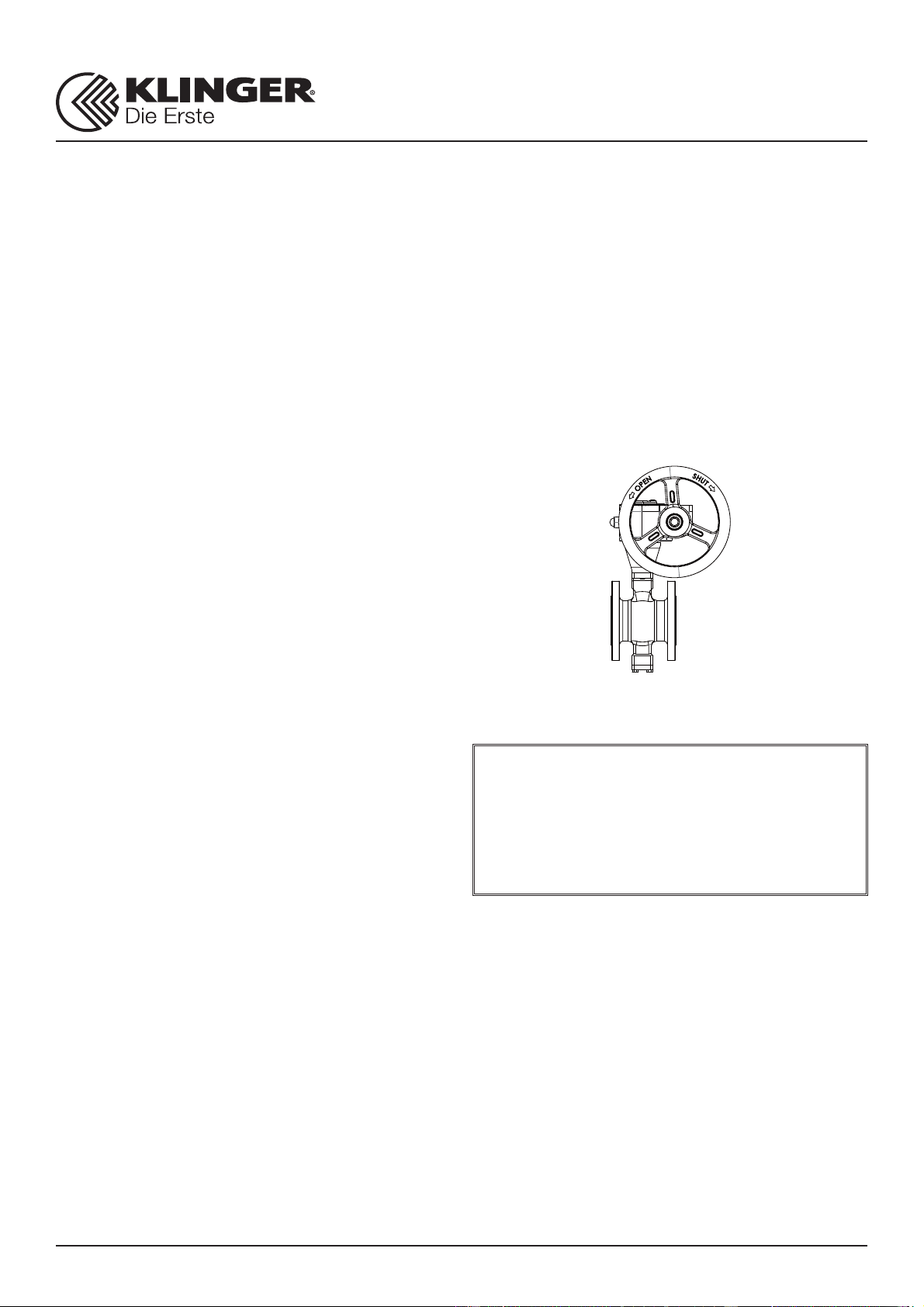
Wafer Type and Flanged V-notch Segment Ball
Valves are generally recommended for throttling
services as well as on-off functions.
Do not touch the valve surface when high tempera-
ture fluid is flowing through the valve.
Do not attempt to open the bonnet and the cap
during operation, especially with the presence of
high pressure in the pipeline system.
For safety concern, unstable fluid should not be
used in the pipeline system, unless otherwise spec-
ified with the category III in Declaration of conformi-
ty.
NOTE:
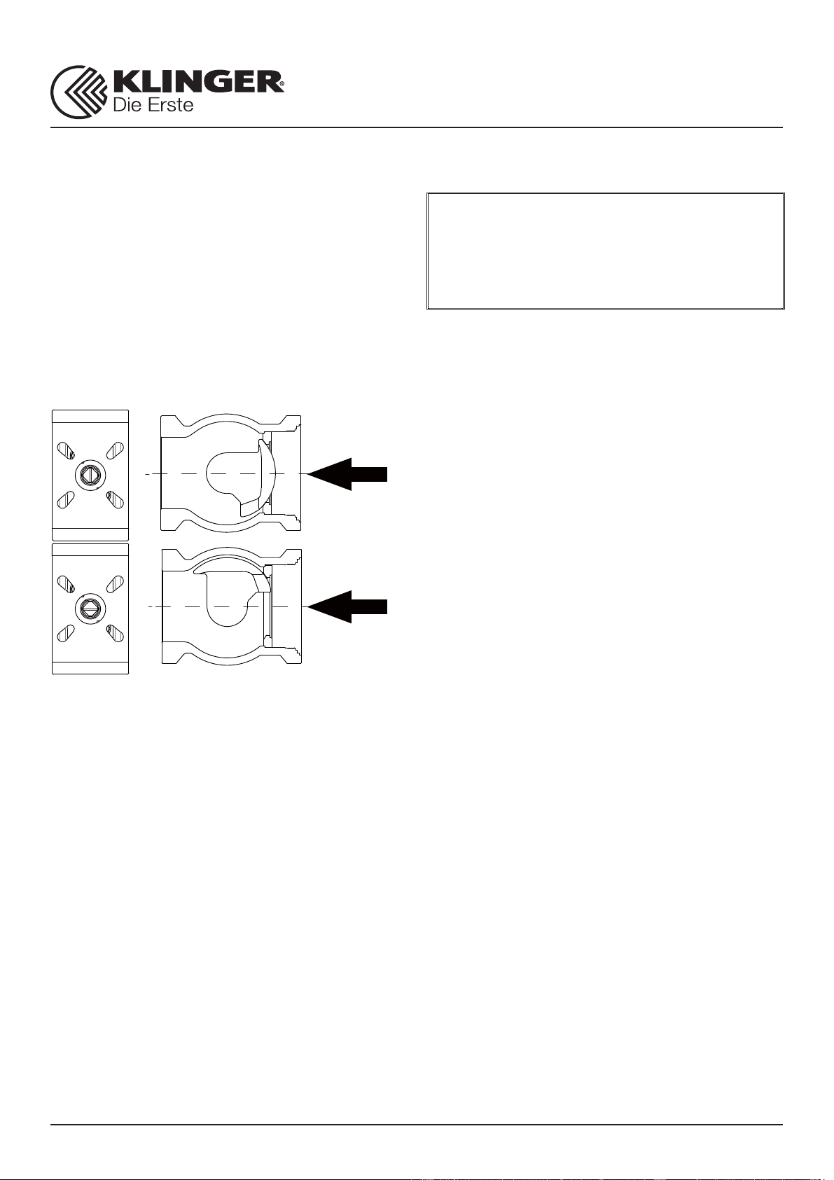
1. KHD-SGF Wafer Type and Flanged V-notch Seg-
ment Valves are installed between flanges. The
body is in one part; the shaft and segment ball are
separated.
2. The valve is either soft or metal seated. De-
pending on customers' requirement, the structure
of the supplied valve may be different.
3. The valve is designed for both control and shut-
off applications.
4. Actuators and accessories are only discussed
briefly. Please refer to individual manuals for fur-
ther information on their IOM manuals.
CAUTION:
Before removing valve from pipeline, operator
should be aware of that: media flowing through
the valve may be corrosive, toxic, flammable, or
of a contaminant nature. Where there is evidence
of harmful fluids having flowed through the valve,
the utmost care must be taken. It is suggested