Showa Denki Mistresa CRM-S Series User manual

0371(E)
−
E
Operation Manual & Cautions
CRMH
−
SSeries CRHSeries
CRM
−
SSeries CRM
−
VSeries
Originalinstructions

1.
2.
3.
4.
5.
6.
7.
8.
9.
10.
11.
12.
13.
14.
15.
16.
Cautionary information indications used in this manual .................
Meanings of symbol marks used in this manual .............................
Using the Mistresa in a safe manner ..............................................
Items to check at product delivery ..................................................
Internal component names and layout ...........................................
Product labels .................................................................................
Ambient conditions in the area of installation .................................
Suction port cautions ......................................................................
Product installation .........................................................................
Piping ..............................................................................................
Operating cautions .........................................................................
Maintenance and inspections .........................................................
Warranty .........................................................................................
Contact information ........................................................................
About Disposal ...............................................................................
Specifications .................................................................................
[Contents]
Thank you for purchasing the Mistresa from Showa Denki. This manual explains the
specifications for the [Mistresa units from CRM-S Series, CRM-V Series, CRMH
Series, and CRH (High Temperature Types) Series].
The Mistresa collects the mist generated while components are manufactured by machine tools.
Please read the operating instructions and cautionary information carefully to ensure that the
Mistresa is used in a safe and efficient manner. Special attention should be given to
cautionary information which bears the [ ] mark.
Keep this manual in a secure location
where it can be easily accessed.
1
1
1
3
4
8
8
9
10
18
20
21
31
32
32
33

−1−
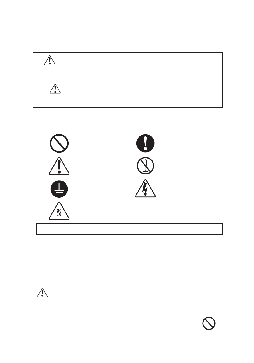
All warnings and instructions must be strictly observed.
A prohibited action
(Target is unspecified)
Failing to heed the
instructions could
result in accidents
Follow instructions
carefully
Disassembly prohibited
Electrical shock hazardElectrical ground required
1.
Cautionary information indications used in
this manual
2.
Meanings of symbol marks used in this manual
"[ ] WARNING" mark indicates cautionary information that, if not
heeded, could result in serious injury or death, and could also
pose a fire hazard.
A "[ ] CAUTION" mark indicates cautionary information that, if not
heeded, could result in injury and/or equipment damage.
WARNING Do not install in hazardous locations
3.
Using the Mistresa in a safe manner
The Mistresa does not have a pressure and explosion-proof construction.
Operating the Mistresa in areas where explosive gases, etc., are present
could result in an explosion in the event of an electric motor burnout.
(CRH-□□E Series except.)
CAUTION! HOT
This product collects oil mist generated by equipment such as machine tools
to ensure and maintain a comfortable working environment. Do not use the
product for any purpose other than the originally intended.

The high efficiency motor (IE3) used with the Mistresas of the CRM-S (H02
excluded), CRM-V (H02 excluded) and CRMH-S series is designed with a lower
winding resistance than the standard motor (IE1 and equivalent), in order to reduce
loss. Since this design feature requires a higher starting current than the
standard motor, replacing your existing motor may require that you also
replace the circuit breaker, thermal relays and other parts.
−2−
CAUTION Cautionary notes on using Mistresas of the
CRM-S, CRM-V and CRMH-S series
WARNING Fire and electrical shock prevention
WARNING Maintenance and inspections prohibited
during impeller rotation
The Mistresa wiring work must be performed by a qualified electrician, and must
conform to the relevant electrical engineering standards and
internal wiring standards.
CAUTION For after installation transport
If you want to transport by installing the product on the device, please
fix firmly with as rope hanging. It may cause malfunction or damage.
Do not hold the Mistresa by the terminal box when moving the unit.
This may deform or damage the unit. Hold the Mistresa somewhere
other than the terminal box or attach the included hanger bolts to lift and
relocate the unit.
Always wait at least 2 minutes after a power OFF before performing
filter replacement work or inspections (to allow the impeller's inertial
rotation to come to a complete stop).
WARNING Fire and explosion prevention
Never allow explosive gases , organic solvents , or flames to be sucked
into the suction port. (CRH-□□E series, please use in the range of 8 page
described.)
Do not touch the product main body or the inside during the operation or
a short while after stopping the operation. Otherwise, "burn" may result.
CAUTION Burn (CRH, CRMH-S Series)
CAUTION Relocating the Mistresa (CRM-V series)

−3−
4.
Items to check at product delivery
Although all our products are thoroughly tested and inspected prior to
shipment, the customer should nonetheless check the following items when
taking delivery of the Mistresa.
• Verify that the delivered product (model, etc.) is the same as
that which was ordered.
• Verify that the product has not been damaged or deformed,
etc., during shipment.
• Verify that all the product accessories are present.
Operation & Cautions Manual
Front
(Primary)
filter
(for replacement)
Drain tube 2.5m
Hose band
(for drain tube)
Anti-vibration pads
Duct companion flange
Packing
(for duct companion flange)
Bolts + nuts
Hanger bolts
Crimp terminals
(1 spare)
Standard Accessories Type
1 copy
1 piece
2 pieces
2 pieces
4 pieces
1 piece
1 sheet
4 sets
2 sets
7 sets
S2□only S2□only V2□only
* Two duct companion flanges come with the product – one for installing
the product and the other for connecting with the next machine. The
packings (for duct companion flanges) for CRM-S, CRMH-S Series are
affixed to the duct companion flanges.
CRM
−
S
Series CRMH
−
S
Series CRM
−
V
Series CRH
Series
—
—
—
—
—
—
—
——
——
**
If necessary, store the Mistresa in ambient conditions below.
・Indoor avoiding direct sun beams
・Temperature between 0°C to 40°C
・Humidity between 10% to 90% (No condensation)
Follow the instructions below if it is necessary to stop the operation or store
the Mistresa for 3 months or longer.
(1) Storing Mistresa in the original packaging
Store the Mistresa in a dry area indoor where the temperature does not
change much.
(2) Not operating the Mistresa after installation
Keep the Mistresa free from "significant vibration" and "heat" from
other machines and equipment.
It is recommended that the Mistresa be covered with a plastic sheet or the
like to keep it free from water, oil and dust.

(1) Internal component names and layout for CRM-S Series and
CRMH-S Series Mistresa
Cover outer cylinder
S□1
Outer cylinder
S□1
−4−
5.
Internal component names and layout
Elbow
Side cover
Motor
Impeller
Suction drain tube
Main body
Discharge drain tube
Front demister (1 piece) S1□
End demister S□2
End Filter S□3
Filter frames S□2
S□3
Front filters (4 pieces) S2□
Filter box
Duct companion flange
Filter case
Cap
Clamp

(2) Internal component names and layout for CRM-V Series Mistresa
Cover outer cylinder
S□1
−5−
Main body
Cap
Clamp
Bottom plate
Drain tube
Metal net
Front demister (1 piece) V1□
Front filters (4 pieces) V2□
Filter box
Filter case
Side cover
Motor
Impeller
End demister V□2
Side demister V□2 only
End Filter V□3
Filter frames V□2
V□3
Metal net retainer V□2
Metal net retainer V□3
Outer cylinder
S□1

End filter
Motor
Side cover “B”
Clamp
Tertiary filter
Main body
Discharge drain tube
Base frame
Reducer
(3) Internal component names and layout for CRH Series Mistresa
①CRH-100T/E
②CRH-200T/E
Secondary filter
Side cover packing
Filter frame
Front de-mister
Primary filter
Primary filter
Metal net
Metal net
Filter retainer
Filter retainer
Duct companion flange
Drain tube
Tertiary filter
End filter
Motor
Side cover
Impeller
Impeller
−6−
Side cover packing
Front de-mister
Side cover “A”
Suction drain tube
Secondary filter (Rotary filter)

Collision plate
Filter case
Primary filter (2 pieces)
Space net
Cap (left and right)
Suction drain tube
Filter box
Duct companion flange
Clamp
Impeller
Secondary filter (2 pieces)
Reducer
Side cover
Main body
Discharge drain tube
Motor
End filter
−7−
③CRH-04E, 07E, 15E

−8−
6.
Product labels
(1) Product nameplate(motor nameplate)………At main body or base frame
The nameplate label contains the following information: product model,
rated voltage, rated frequency, rated current, insulation class, max. static
pressure, max. airflow rate, manufacture No., etc.
Note 1: The "ratings" are the operating limit values.
Note 2: The static pressure is the force which a gas flow applies to faces
which are parallel to that flow.
(2) Ground connection………Inside the terminal box
The " " mark indicates a ground connection.
Be sure that the mark-indicated part is securely grounded.
(3) Warning label………Filter case (CRH Series)
Warning label that prohibits removing the caps or covers while the
impeller is rotating
Wait for [at least 2 minutes] after turning off the power supply and
before opening the caps or the covers. The inertia keeps the impeller
rotating even after turning off the power supply. Otherwise, a [finger or
wrist] injury could result.
(4) Caution label………Side cover or top panel (CRH and CRMH-S Series)
Burn hazard. Do not touch the main body during operation or
immediately after stopping operation. Burn could result.
7.
Ambient conditions in the area of installation
CAUTION
Resulting in motor burnout and deterioration of the components.
Be sure to use within the range described following.
Ambient temperature
Intake temperature
Relative humidity
Altitude
Overvoltage category
Material group
Level of contamination
0°C to 50°C
50°C or lower
10% to 90%
1,000 meters or lower
III
III
3
0°C to 40°C
80°C or lower
CRM-S Series
CRM-V Series CRMH-S Series
CRH Series

−9−
NEVER allow the following items to flow into the product - Explosive
gases, organic solvent, sparks, burning cigarettes and so forth. Otherwise, an
explosion, fire or product damage could result.
Using a CRH-□□E Series product equipped with a quasi-explosion-proof
motor, however, allows Class 2 petroleum mist (such as kerosene) and Class
3 petroleum mist or higher of Class 4 hazardous substances to flow into the
product. However, make absolutely sure that the mist temperature is below
the flash point.
Since the CRH Series Mistresa use oil seals on the shafts, be sure to make
the mist flow into the product for lubrication. (See (6) in section
“Cautionary Notes on Operation” on page 20.)
* Class 3 petroleum mist having the flash point higher than 150°C may flow
into the CRM-S, CRM-V or CRMH-S Series Mistresa provided that the
suction temperature of the mist is 50°C or lower (80°C or lower for the
CRMH Series). Be absolutely sure to use the burnout prevention terminals
A and B (white leads) in the operation circuit so that the motor would not
experience an excessive temperature.
* Note that some mist substances may deteriorate the packings and filters.
WARNING
8.
Suction port cautions
・Install the Mistresa indoor.
・Make sure that the installation floor has a sufficient bearing
strength commensurate with the machine weight.
・Install the Mistresa where it stays away from strong vibration
or impact.
・Install the Mistresa on a level, flat surface.
・Do not install in an environment where explosive gases, etc.,
may be present. (Excluding CRH-□□E Series Mistresa)

−10−
9.
Product installation
(1) Installation method
CAUTION
Common to all models:
・Before opening the package, make sure it is right side up.
・Check the weight of the Mistresa before lifting it and use the right sling
for the rated work load.
・Confirm that the hanger bolts are not loose.
・Hook the lifting hooks on the hanger bolts to lift the Mistresa.
・Do not suddenly move the Mistresa up or down, or suddenly start or
stop lifting in any way that shocks the Mistresa.
・Do not hold the Mistresa by the terminal box when transporting it.
・After installing the Mistresa on the machine, do not lift the Mistresa
together with the machine using the hanger bolts.
・When lifting a Mistresa of the CRM-S series (horizontal type), use the
eye bolts located on the top of the Mistresa.
・When lifting the CRM-V series (vertical type), replace the bolts at the
top of the Mistresa with the eye bolts included in the product package.
・Replace the diagonally opposite bolts on the top of the Mistresa with
the eye bolts.
①CRM-S Series, CRMH-S Series, CRH Series
aInstall in a horizontal (level) manner to evenly distribute the weight of
the drain pipe discharge and the anti-vibration pads.
bWhen installing the product
on top of another machine,
etc., secure it with bolts to
prevent shifting due to
vibration.
cLeave a gap at the securing
bolts to allow the anti-
vibration pads to function
properly (See Fig.1).
Fig.1
As viewed from "A"
2 to 3mm Double nut
Gap
Anti-vibration pad
Welded bolt

−11−
dThe liquid seal surface should be
300mm or farther below the
drain pipe in order to allow
drain pipe discharge. An
optional floor stand with a
height of 600mm is available
(see Fig.2) (For drain piping
details, see page 19, item (3)
"Drain tube piping").
e Leave a 500mm margin of
space at all sides of the
product to permit filter
replacements, maintenance,
and inspections.
②CRM-V Series
Do not hold the Mistresa by the terminal
box when moving the unit. Hold the
Mistresa somewhere other than the
terminal box or attach the included
hanger bolts as shown in the photo at
right* to lift and relocate the unit.
*Remove the screws that lock down the
side covers.
Fig.2
A
300m m

−12−
Mark the center of the air intake
port on the surface where installing
the Mistresa.
Mark the center of one of the drain
pipes, at the distance from the
mark made in ❶specified in the
installation dimensions on pg. 2.
Dimension A
H02, H04 : 118 mm
H07 : 138 mm
H15 : 168 mm
H22 : 187 mm
Air intake port center
Installation hole center
Drain pipe center
A
A
Drain pipe center
Drain pipe center
Drain pipe center
Drain pipe center
Mark the center of the other drain
pipe, along the line drawn through
the marks made in ❶and ❷.
Distance from the mark drawn in ❷
H02, H04 : 335 mm
H07 : 390 mm
H15 : 475 mm
H22 : 530 mm
Mark the centers of the installation
holes (x 2), along the line drawn
through the marks made in ❷
and ❸.
Distance from the mark drawn in
❷and ❸
H02, H04 : 51.7 mm
H07 : 59.6 mm
H15 : 66.6 mm
H22 : 67.3 mm
1 2
34
Air intake port center

−13−
B
B
Mark the centers of the remaining
installation holes (x 2), at the
distances from the installation
holes marked in ❹specified in the
installation dimensions on pg. 2.
Dimension B
H02、H04 : 310mm
H07 : 360mm
H15 : 430mm
H22 : 470mm
The centers of the installation
holes marked in ❹and ❺can
also be marked without doing
any measuring, by drilling the
holes marked in ❶, ❷and ❸,
loosely anchoring the Mistresa
and then tracing the holes.
However, move the Mistresa out
of the way to drill the φ10 holes.
Open the holes around the marks,
with a hole saw, etc.
Air intake port (Center)
H02, H04: φ105 mm
H07: φ130 mm
H15: φ160 mm
H22: φ210 mm
Drain pipes: φ30 mm
(Same for all models)
Installation holes: φ10 mm
(Same for all models)
Set the Mistresa in place and lock
it down with the nuts and bolts.
5
67
Installation
hole center
Installation
hole center
marked in ❹
Installation
hole center
marked in ❹

−14−
Mistresa CRM-V Installation Dimensions
CRM-H02-V□□、CRM-H04-V□□ CRM-H07-V□□
CRM-H15-V□□ CRM-H22-V□□

−15−
CAUTION
CAUTION
aInstall the Mistresa level so that oil properly drains from the unit.
bUsing bolts and nuts, connect the Mistresa to the machine/equipment.
(CRM-V series Mistresas do not require a duct hose or drain tube.)
c Ensure about 500 mm of clearance on all sides of the Mistresa for
checks, maintenance and parts replacement.
Outside of machine/
equipment
Machine/
Equipment
Inside of machine/
equipment
(2) Power supply connection
WARNING
①Be sure that the power supply conforms to the rated voltage and rated
frequency requirements.
• When using inverter controlled operation, protect the motor by
incorporating the motor burnout prevention terminals "A" and "B"
in the inverter's control circuit.
In addition, if it is inverter operation at different voltage (more
than 380V), you will need a motor insulation strengthening.
• Permissible voltage fluctuation range:
Continuous…Rated voltage within ±5%
Momentary…Rated voltage within ±10%
②Please connect the ground wire sure.
③CRH Series: The impeller rotates clockwise when viewed from the
motor. Make sure that impeller rotates in the correct
direction before starting operation.
CRM-S Series, CRM-V Series, and CRMH-S Series
: The impeller can rotate either clockwise or
counterclockwise direction.

−16−
④The terminals A and B (with white leads) on the CRM-S, CRM-V,
and CRMH-S Series are for motor burnout prevention. See (4) for
their connection and use.
⑤When using crimp terminals, either cover the crimp area with an
insulation tube, or use insulated type crimp terminals.
⑥ When wiring the power supply, immobilize the cable at the
cable port using a cable lock or similar means, so that external
force is not applied to terminals.
If a cable lock comes with a customized product, wire the
power supply as follows.
Procedure
:
1. Select the bush commensurate
with the cord from the
attached bushes.
2. Put the cord through the cord lock.
3. Tighten the fastener band to secure the cord in place. Check that
the cord is securely tightened.
Screw size
M3.5
Tightening torque
0.87N·m (max0.96N·m)
Installation nut Main body
Bush S Bush M
Fastener band
Bush symbol
S
M
None
Applicable cord diameter
(
mm
)
6.0 to 8.0
8.0 to 10.0
10.0 to 12.0
Models
CRM-H02, CRH-100T/E, CRH-200T/E
CRM(H)-H04, CRH-04E
CRM(H)-H07, CRH-07E
CRM(H)-H15, CRH-15E
CRM(H)-H22
AWG16 (≒1.25 mm2)
AWG16 (≒1.25 mm2)
AWG16 (≒1.25 mm2)
AWG14 (≒2.0 mm2)
AWG14 (≒2.0 mm2)
AWG16 (≒1.25 mm2)
AWG16 (≒1.25 mm2)
AWG16 (≒1.25 mm2)
AWG14 (≒2.0 mm2)
AWG14 (≒2.0 mm2)
Cross-sectional area of copper
conductor that supplies power
to the equipment
Minimum cross-sectional area
of the external protection
copper conductor
Minimum cross-sectional area of the external protection copper conductor

−17−
(3) Using the burnout prevention terminals
The CRM-S, CRM-V, and CRMH-S Series Mistresa have a heat-sensitive
thermal protector at the motor winding. This auto reset thermal protector
operates as follows. When the motor winding temperature rises
excessively high, the relay contacts open. When the temperature comes
back down to a certain temperature, the contacts automatically close
again. Connect the thermal protector with the terminals A and B for
burnout prevention.
By connecting this terminal in series with the operating circuit of the
electromagnetic switch (with thermal relay), to prevent motor burnout.
CAUTION
①Be sure to connect the "A" and "B" terminals to the operation circuit
in order to protect the motor.
② Use the prescribed or lower contact rating (115V AC, 18A / 230V
AC, 13A / 24V DC, 18A).
③ When the thermal relay is tripped, correct the cause, then press the
[RESET] button.
④The thermal relay may be erroneously tripped if the Mistresa is operated
in an intermittent manner. In this case, change the thermal relay.
a) Connection example for burnout prevention terminals "A" and "B"
Electromagnetic switch device (with thermal relay) Please prepare.
Power supply
When using
an electromagnetic
switch Terminal box
Thermal protector
THRMC
THRMC
ON OFF
MC

−18−
b) Connection example when using the optional switch with built-in
3SW thermal and a 3m cable)
⑤Check the rated current shown on the nameplate of the Mistresa and set
the thermal current to the rated current.
Power supply
Terminal box Thermal protector
Switch
10.
Piping
CRM-V series Mistresas do not use a duct hose or drain tube, so neither
needs to be connected to the unit.
Connect the Mistresa directly to the machine/equipment.
(1) Duct hose material
Because the life of the duct hose will vary according to the type of mist
being sucked in, the use of an oil-resistant duct hose is recommended.
(2) Intake duct piping
①A flexible duct (optional item) should be used to facilitate easy duct
maintenance and vibration resistance.
②The duct should be somewhat longer than strictly necessary (slight
length surplus), but it must not sag when connected.
③Use the duct companion flange (accessory item) to facilitate easy
connection.
OK example OK OK
Mist generation source Mist generation source
NG example NG
Mist generation source
Sagging (drain will accumulate here)
(cable 3m)
}
This manual suits for next models
29
Table of contents
Other Showa Denki Industrial Equipment manuals