CP Autosport SetupWizzard User manual


Wheel alignment system SetupWizzard
Year of manufacture: from 2015
Version 01
Edition: October 2019
© CP Tech GmbH
This operating manual and all illustrations contained herein are protected by copyright. Any use outside
the limitations of copyright law without our prior written approval is prohibited and liable to prosecution.
This applies especially to reproduction, translation, microfilming, saving, and editing in electronic
systems.

Wheel alignment system SetupWizzard I
Contents
1Introduction ......................................................................................................................................1
1.1 Notational conventions.............................................................................................................2
1.1.1 Section-related warnings ............................................................................................2
1.1.2 Embedded warnings ...................................................................................................3
1.1.3 Other notational conventions......................................................................................3
1.1.4 Symbols used in the manual ......................................................................................3
1.2 Warranty and liability................................................................................................................4
1.3 Copyright..................................................................................................................................5
1.4 Guarantee terms ......................................................................................................................5
1.5 Service / Customer service ......................................................................................................5
2Safety.................................................................................................................................................6
2.1 Intended use ............................................................................................................................6
2.1.1 Structural alterations to the measuring system ..........................................................7
2.1.2 Foreseeable misuse ...................................................................................................7
2.2 Personnel requirements...........................................................................................................7
2.2.1 Responsibilities...........................................................................................................8
2.2.2 Obligations of personnel.............................................................................................8
2.2.3 Unauthorized persons ................................................................................................8
2.2.4 Instruction ...................................................................................................................9
2.3 General safety information.......................................................................................................9
2.4 Safety measures for environment protection .........................................................................10
2.5 Special hazard signs..............................................................................................................10
2.5.1 Symbols used on the measuring system..................................................................10
2.5.2 Hazards due to electricity .........................................................................................11
2.5.3 Hazards due to hot surfaces.....................................................................................12
2.5.4 Hazards due to incorrect spare parts .......................................................................12
2.6 Personal protective equipment ..............................................................................................13
2.7 Safety devices and guards.....................................................................................................13
2.8 Information for emergencies ..................................................................................................14
2.9 Obligations of the plant operator............................................................................................15
3Description of the measuring system ..........................................................................................16
3.1 Scope of supply .....................................................................................................................16
3.1.1 Scope of supply of the system version Easy............................................................16
3.1.2 Scope of supply of the system version Basic ...........................................................17
3.1.3 Scope of supply of the system version Pro ..............................................................18
3.1.4 Accessories for system version Pro .........................................................................19
3.1.4.1 Rating plate ...............................................................................................19
3.2 Function .................................................................................................................................20
3.3 Technical data........................................................................................................................20
3.3.1 Measuring platform (System version Pro) ................................................................20
3.3.2 Camber sensor (System version Pro) ......................................................................20
3.3.3 Toe laser...................................................................................................................20
3.3.4 Leveling laser (see technical specification user manual) .........................................20
3.3.5 Transport box (flight case)........................................................................................21
3.3.6 Platform elevations (accessories).............................................................................21
3.3.7 Ambient conditions ...................................................................................................21

Contents
II CP Tech GmbH
4Transport and storage (by manufacturer)................................................................................... 22
5Transport and storage (by plant operator) ................................................................................. 23
5.1 Safety during transport .......................................................................................................... 23
5.2 Intermediate storage ............................................................................................................. 24
6Installation by manufacturer ........................................................................................................ 25
7Installation by plant operator ....................................................................................................... 26
7.1 Adjusting the universal stands of the setup wheel ................................................................ 26
7.2Replacing the wheel adapters............................................................................................... 30
7.3 Setting up the software.......................................................................................................... 31
7.3.1 Measuring platform operation .................................................................................. 33
7.3.2 Pairing the measuring platform ................................................................................ 34
7.3.3 PC software configuration........................................................................................ 35
7.3.4 Taring the wheel load scales ................................................................................... 36
8Commissioning.............................................................................................................................. 37
8.1 Safety measures to be taken before commissioning ............................................................ 37
8.1.1 Necessary operating and maintenance space......................................................... 37
8.1.2 Floor requirements ................................................................................................... 37
8.2 Setting up the measuring system.......................................................................................... 38
8.2.1 Installing the setup wheels....................................................................................... 38
8.2.2 Positioning the platforms/measuring platforms........................................................ 38
8.2.2.1 Using the positioning laser (optional) ....................................................... 39
8.2.3 Leveling the measuring platforms............................................................................ 39
8.2.4 Lowering the vehicle onto the measuring platforms ................................................ 40
8.2.5 Adjusting the toe laser ............................................................................................. 41
8.2.6 Functional testing of the toe lasers .......................................................................... 43
8.2.7 Adjusting the camber sensors (inclinometer)........................................................... 44
9Operation........................................................................................................................................ 46
9.1 Safety measures during normal operation ............................................................................ 46
9.2 Measuring the suspension .................................................................................................... 46
9.2.1 Measuring the wheel loads ...................................................................................... 46
9.2.2 Measuring the camber ............................................................................................. 47
9.2.3 Measuring the toe .................................................................................................... 47
9.2.4 Measuring the ride height ........................................................................................ 49
9.3 Operating the accessory components................................................................................... 50
9.3.1 Caster measurement ............................................................................................... 50
9.3.2 Platform elevations .................................................................................................. 52
9.3.3 Longer platform stands ............................................................................................ 52
9.3.4 CAN charger ............................................................................................................ 53
10 Faults and remedial measures..................................................................................................... 54
11 Service ............................................................................................................................................ 55
11.1 Safety measures when carrying out service ......................................................................... 55
11.2 Inspection and service work.................................................................................................. 56
11.2.1 Revision SetupWizzard............................................................................................ 56
11.2.2 Accumulators ........................................................................................................... 57
11.2.3 Batteries .................................................................................................................. 58

Contents
Wheel alignment system SetupWizzard III
11.2.4 Special service intervals ...........................................................................................58
11.2.4.1 Electrical equipment..................................................................................58
11.2.5 Service of third-party components............................................................................58
12 Decommissioning and disposal ...................................................................................................59
12.1 Decommissioning / Dismantling the machine ........................................................................59
13 Appendix .........................................................................................................................................60
13.1 EC Declaration of Conformity / Declaration of incorporation .................................................60
13.2 Attached documents ..............................................................................................................61

Contents
Wheel alignment system SetupWizzard 1
1 Introduction
Dear customer,
Thank you for deciding in favour of the SetupWizzard.
This operating manual provides all the information you need to operate the Wheel
alignment system SetupWizzard properly.
All persons responsible for operating, maintaining, cleaning, and troubleshooting the
measuring system must read, understand and heed the operating manual. This applies in
particular to the safety information that is given.
After reading the operating manual you will be able to
–Operate the measuring system safely
–Clean the measuring system according to the rules and regulations
–Take the necessary action in the event of a fault.
In addition to this operating manual, it is necessary to comply with the general laws and
other regulations concerning accident prevention and environmental protection in the
country of use.
This operating manual must always be kept at the measuring system’s point of deployment.

Contents
2CP Tech GmbH
1.1 Notational conventions
Passages of this operating manual that require special attention or are a direct hazard
warning are shown as follows:
1.1.1 Section-related warnings
Section-related warnings are not limited to just one specific action but apply to all the
actions performed within a section.
Structure
SIGNAL WORD
Symbol
that
describes
the danger
in more
detail
Type and source of danger
Possible consequence(s) of failure to comply
–Measure(s) to avoid the danger
Danger levels
DANGER
Hazard which, unless avoided, may involve a high risk of death or serious
injury.
WARNING
Hazard which, unless avoided, may involve a medium risk of death or
serious injury.
CAUTION
Hazard which, unless avoided, may involve a minor risk of negligible or
moderate injury.
NOTE
Hazard which, unless avoided, may involve a low risk of material damage.
Contents
Wheel alignment system SetupWizzard 3
1.1.2 Embedded warnings
Embedded warnings apply to specific actions and are integrated directly in the action.
Structure
KEY WORD Type and source of the danger
Possible consequences of non adherence
–Measures to avoid the danger
Danger levels
–DANGER / WARNING / CAUTION
–NOTE
For explanations of the danger levels, see „1.1.1 Section-related warnings”.
1.1.3 Other notational conventions
The info symbol provides useful information.
–
Text following this mark represents an item in a list.
•
Text following this mark describes actions to be performed in the specified order.
„”
Text in double quotation marks refers to other chapters or sections.
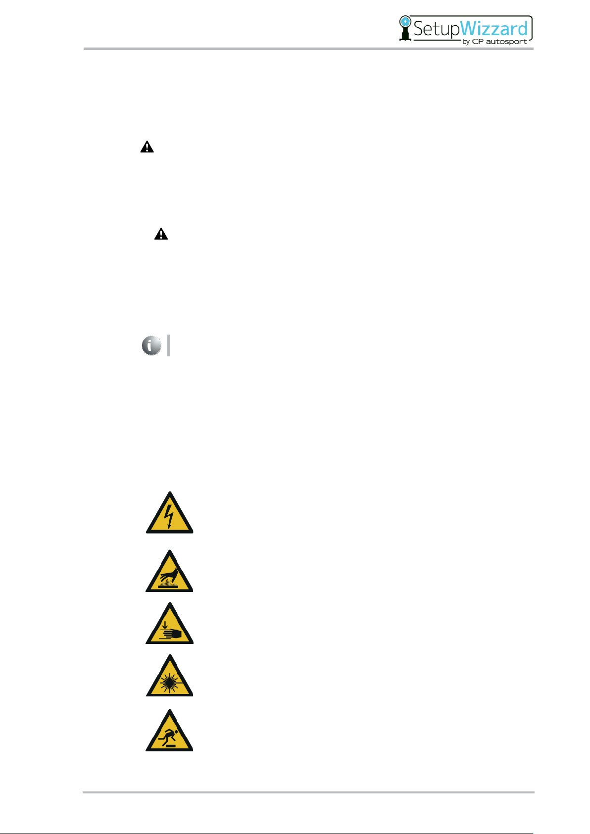
1.1.4 Symbols used in the manual
Particular hazards in connection with hazard warnings are shown in addition as follows:
Fatal injury hazard due to electricity
This symbol warns of a fatal injury hazard due to electricity.
Contact with live parts is a direct fatal injury hazard.
Warning of hot surface
This symbol warns of a burn hazard due to hot surfaces.
Warning of hand injury
This symbol warns of hand injuries when setting up the measuring system.
Warning of laser beams
This symbol warns of laser beams (leveling laser, toe laser, positioning
laser).
Warning of obstacles on the ground
This symbol warns of obstacles on the ground (cables, tools, ...).

Contents
4CP Tech GmbH
1.2 Warranty and liability
The obligations under the supply contract, the general delivery terms and conditions of the
measuring system and the legal regulations in force at the time the contract was signed will
apply.
All information in this operating manual has been compiled in line with the applicable
standards and regulations, the state of the art, and our longstanding knowledge and
experience.
Warranty and liability claims for personal injury and material damage are excluded if they
are attributable to one or more of the following causes:
–Unintended or inappropriate use of the measuring system
–Inappropriate installation, commissioning, operation, maintenance or cleaning of the
measuring system
–Operation of the measuring system with defective safety devices or with improperly
fitted or non-functional safety devices and guards
–Failure to heed information in the operating manual regarding installation,
commissioning, operation, maintenance, and cleaning of the measuring system
–Use of unqualified or inexperienced personnel
–Structural alterations to the measuring system (conversions or other alterations to the
measuring system are not allowed to be made without prior written permission from
CP Tech GmbH. Any breach of this causes the measuring system to lose its EC
conformity).
–Improperly executed repairs
–Use of non-permitted spare parts or of spare parts that do not satisfy the technically
established requirements
–Disasters, effects of extraneous elements and force majeure
We reserve the right to make technical alterations in the course of further development and
improvement of features.

Contents
Wheel alignment system SetupWizzard 5
1.3 Copyright
This operating manual is protected by copyright and intended for internal use only.
This operating manual or parts thereof must not be passed or disclosed to any third party
or be reproduced or exploited in any form without the prior written consent of
CP Tech GmbH except for internal use.
Contravention results in liability for damages. Further claims remain reserved.
1.4 Guarantee terms
The guarantee terms are contained in the general terms and conditions of CP Tech GmbH.
1.5 Service / Customer service
Our Customer Service department is at your disposal for any technical queries you
may have.
CP Tech GmbH
Dornierstraße 7
33142 Büren / Germany
Phone: +49 (0) 2955 / 4849-553
www.setupwizzard.com
In addition, our employees are consistently interested in new information and
experiences resulting from the application that may be of value in improving our
products.

Contents
6CP Tech GmbH
2 Safety
Failure to observe the safety information below may have serious
consequences:
–Risk to persons due to electrical, mechanical or chemical effects
–Failure of important functions
–Environmental damage due to leaking hazardous substances
Read the safety and hazard information in this section thoroughly before putting
the measuring system into operation.
In addition to the information specified in this operating manual, always comply with
general safety and accident prevention regulations.
Follow internal rules and regulations.
In addition to the information specified in this operating manual, the plant
operator/system operator must comply with national occupational, health and
safety regulations.
2.1 Intended use
The safety of the measuring system is only ensured if it is used as intended.
The measuring system is only intended for the measurement of vehicle suspension.
The measuring system is not intended for use other than as described here; other use
counts as inappropriate. In addition, the measuring system is only approved for vehicles
with a total vehicle weight of up to 2000kg or 500kg/wheel.
Intended use also includes:
–Observing all information from the operating manual
–Complying with the inspection and maintenance intervals
–Complying with the operating conditions
The technical specifications mentioned in the technical data must be complied with without
exception.
Only use the measuring system as intended; otherwise there is no guarantee of
safe and reliable operation.
It is not the manufacturer but the plant operator who is responsible for any and all
personal injuries and material damage resulting from unintended use.

Contents
Wheel alignment system SetupWizzard 7
2.1.1 Structural alterations to the measuring system
Construction and manufacturer's acceptance are based on the German Product Safety Act
(ProdSG). The measuring system is not allowed to be converted or otherwise altered
without prior written permission from CP Tech GmbH.
Any breach of this causes the measuring system to lose its EC conformity. Such a breach
absolves the manufacturer of the measuring system from warranty. This also applies to
welding work on components.
Any parts not in a perfect state must be replaced immediately.
Use original spare/wearing/accessory parts only. These parts have been specifically
designed for the measuring system. For parts from other sources there is no guarantee
that they have been designed and manufactured in line with load and safety requirements.
Parts and special features not delivered by CP Tech GmbH have not been released for use
with the measuring system.
2.1.2 Foreseeable misuse
Any use exceeding the concept of intended use and/or other use of the measuring system
can lead to severe injuries.
–Only use the measuring system for its intended purpose.
2.2 Personnel requirements
The measuring system is only allowed to be operated, maintained, and repaired by persons
who have been qualified and/or trained for this. These persons must know the operating
manual and act in accordance with it. The respective authorizations for personnel must be
defined clearly.
Personnel require the following qualifications for the various activities:
Qualified, instructed personnel (in this case, e.g., automotive mechatronics technicians)
Qualified personnel are able to do their work and recognize/avoid potential hazards on their
own as a result of their training, knowledge and experience and their familiarity with
regulations.
Electrical specialists
Electrical specialists are able to work on electrical equipment and recognize/avoid potential
hazards on their own as a result of their training, knowledge and experience and their
familiarity with standards and regulations.
Electrical specialists have been trained for their specific point of deployment and know the
relevant standards and regulations.

Contents
8CP Tech GmbH
2.2.1 Responsibilities
Inappropriate handling can lead to severe personal injury and material damage.
All activities must therefore be carried out by qualified personnel only.
–Personnel must consist of individuals who can be expected to perform their work
reliably. Individuals whose response is impaired by drugs, alcohol, medication, and the
like must not work on the measuring system.
–All persons working on the measuring system must read the operating manual and
confirm with their signature that they have understood it.
–Initially, personnel requiring training are only allowed to work on the measuring system
under the supervision of qualified personnel. The completion and success of instruction
must be confirmed in writing.
The plant operator is responsible for training and instructing personnel.
2.2.2 Obligations of personnel
Before working on or with the measuring system, all persons undertake the following:
–To comply with basic regulations concerning health and safety and accident prevention.
–To read the safety information and warnings in this operating manual and to confirm
with their signature that they have understood the issues.
2.2.3 Unauthorized persons
Unauthorized persons who do not have the required qualifications are not aware of the
hazards in the work area.
–Keep unauthorized persons away from the work area.
–Address persons in case of doubt and eject them from the work area if applicable.
–Interrupt work while any unauthorized persons are in the work area.

Contents
Wheel alignment system SetupWizzard 9
2.2.4 Instruction
The plant operator must instruct personnel at regular intervals. Keep a record of all
instructions given in order to keep track of matters.
Date
Name
Type of
instruction
Instruction given
by
Signature
2.3 General safety information
–Always read and understand the operating manual before operating and maintaining
the measuring system.
–Only use the measuring system for its intended purpose
(see „2.1 Intended use”).
–Do not work on the measuring system when other persons are present in the danger
zone.
–Refrain from any act which is likely to compromise the health and safety of people and
safe operation of the measuring system.
–Never operate the measuring system without the associated guards and safety devices.
Never take installed safety devices out of operation.
–Always keep the work area around the measuring system clean and tidy to prevent
hazards due to dirt and things lying around.
–Do not exceed the technical data (see „3.3 Technical data”).
–Keep all safety and hazard signs on the measuring system in a legible state and renew
them if necessary.
–Only qualified or trained personnel are allowed to operate or work on the measuring
system (see „2.2 Personnel requirements”).
–Take the measuring system out of operation immediately if a fault occurs. Have faults
rectified by appropriately trained specialists or by CP Tech GmbH.
–Always keep the operating manual at the measuring system’s point of deployment. It
must be ensured that all personnel working on the measuring system can view the
operating manual at any time.

Contents
10 CP Tech GmbH
2.4 Safety measures for environment protection
In all work obey the regulations for waste avoidance and proper waste disposal/recycling.
In the course of installation, maintenance and decommissioning, in particular, it must be
ensured that materials which could jeopardize the groundwater –such as greases, oils,
coolants, solvent-containing cleaning fluids and the like –do not pollute the ground or get
into the drains. These materials must be caught, kept and transported in suitable containers
and disposed of in compliance with national regulations.
2.5 Special hazard signs
2.5.1 Symbols used on the measuring system
Fatal injury hazard due to electricity
This symbol warns of fatal injury hazard due to electricity.
Contact with live parts is a direct fatal injury hazard.
Warning of hot surface
This symbol warns of a burn hazard due to hot surfaces.
Warning of hand injury
This symbol warns of hand injuries when setting up the measuring system.
Warning of laser beams
This symbol warns of laser beams (leveling laser, toe laser, positioning laser).
Warning of obstacles on the ground
This symbol warns of obstacles on the ground (cables, tools, ...).
Keep all safety and hazard signs on the measuring system in a legible state. Renew
the signs if necessary.
Contents
Wheel alignment system SetupWizzard 11
2.5.2 Hazards due to electricity
DANGER
Voltage
There is a hazard of electric shock from contact with live parts.
–Make sure electrical components are always fully closed.
–Have work at electrical equipment only be carried out by electrical
specialists who, as a result of their training, knowledge and experience,
are able to recognize and avoid potential hazards.
–Observe the five golden safety rules:
1. Disconnect completely
2. Secure against reconnection
3. Verify that it is disconnected
4. Carry out grounding and short circuiting
5. Project against live parts
DANGER
Voltage
An electric shock may have a number of secondary effects that lead to
additional injury (e.g. falling if working at height).
–Always observe the five golden safety rules when working on electrical
equipment.
–Only have electrical specialists carry out work on the electrical equipment.
–Before working on electrical equipment, switch off the measuring system and prevent
unexpected restoration of power.
–Only electrical specialists - e.g. plant electricians - are allowed to work on the electrical
equipment.
–Regularly check the electrical equipment for defects such as loose connections or
scorched cables. Have any defects rectified immediately.
–Have the electrical equipment and fixed electrical apparatuses tested by an electrical
specialist every 4 years at least.
Fixed electrical apparatuses are permanently installed apparatuses or apparatuses that
do not offer any carrying device and which, due to their weight, are difficult to move.
This also includes electrical equipment that is fitted on a temporary basis and operated
using movable device cabling.
–Have portable electrical equipment and extension and device cabling with plugs and
sockets tested by an electrical specialist, or by a trained person using suitable
inspection facilities, every 6 months at least.
Equipment is portable if, by its nature and in its normal use, it is moved while under
power. This includes, for example, electric floor cleaners.
–Alterations at electrical equipment made after testing must comply with DIN EN
60204-1.

Contents
12 CP Tech GmbH
–Check correct functioning of all the measuring system’s safety devices regularly.
–Only use original fuses.
–Have a damaged housing and pipes/hoses/cables repaired or replaced immediately
before switching on the measuring system.
–Ground the measuring system.
2.5.3 Hazards due to hot surfaces
Contact with hot parts can cause burns.
–Always wear protective clothing and safety gloves when working near hot parts (wheel
support, brake discs, brake caliper).
–Before maintenance and repair work, let all machine components cool down to the
ambient temperature.
2.5.4 Hazards due to incorrect spare parts
Incorrect or faulty spare parts may cause damage, malfunctioning or total failure, and may
also give rise to safety hazards.
–Use original spare parts only.
–Procure spare parts via CP Tech GmbH.
For the ordering of spare parts our customer service is at your disposal:
CP Tech GmbH
Dornierstraße 7
33142 Büren / Germany
Phone: +49 (0) 2955 / 4849-553
www.setupwizzard.com
In addition, our employees are consistently interested in new information and
experiences resulting from the application that may be of value in improving our
products.

Contents
Wheel alignment system SetupWizzard 13
2.6 Personal protective equipment
During measuring system operation, always wear personal protective equipment,
irrespective of the risk assessment at work, to minimize health hazards.
–Always wear the personal protective equipment required for the respective task when
carrying out work.
–Never wear rings, necklaces or other jewelry.
–In the work area, obey all signs relating to personal protective equipment.
Protective clothing
Protective clothing refers to tight-fitting working clothes that tear easily and
feature tight sleeves and no loose parts. They predominantly protect against
becoming entangled in moving machine parts.
Safety shoes
Wear non-slip safety shoes to protect yourself against heavy falling parts and
prevent you from slipping.
Safety gloves
Wear safety gloves to protect your hands against friction, abrasion, puncture
wounds or deeper injuries as well as against coming into direct contact with
hot surfaces or chemical substances.
The personal protective equipment must be provided by the plant operator and must be fit
for purpose.
It is also necessary to obey national regulations, the guidelines of the risk assessment at
work and, if applicable, the operator's internal instructions.
2.7 Safety devices and guards
–Before switching the measuring system on, always make sure that all safety devices
and guards have been fitted properly and are functional.
–When subcomponents are delivered, the plant operator must ensure that the guards are
fitted according to the rules.

Contents
14 CP Tech GmbH
2.8 Information for emergencies
Preventive measures
–Always be prepared for accidents or fires.
–Keep first aid equipment (first aid box, blankets etc.) and fire extinguishers at hand.
–Familiarize the personnel with accident reporting, first aid, fire-extinguishing, and rescue
equipment.
–Keep access routes for rescue vehicles clear.
Measures in the event of accidents
–Bring persons out of the danger zone.
–In the event of cardiac and/or respiratory arrest, initiate a resuscitation attempt
immediately.
–If anybody is injured, notify the first aid officer and the emergency medical service.
–Clear the access routes for rescue vehicles. If necessary, appoint a member of staff to
engage with fire and rescue services upon arrival and to provide them with the
appropriate information.
–Extinguish any burning oil/grease with a CO2or powder extinguisher.
–Use a CO2extinguisher to put out any fire in the electric control system.

Contents
Wheel alignment system SetupWizzard 15
2.9 Obligations of the plant operator
The measuring system is used in the commercial and private sector. The plant operator is
therefore subject to the legal requirements concerning health and safety at work.
In addition to the safety information in this operating manual, it is necessary to comply with
the safety, accident prevention and environmental protection regulations in force where the
measuring system is being used. The following applies in particular:
–The plant operator must ensure that the measuring system is only used as intended
(see „2.1 Intended use”).
–The plant operator must always keep the operating manual in a legible and complete
state at the measuring system’s point of deployment.
–The plant operator must clearly define and arrange the responsibilities for installation,
commissioning, operation and cleaning.
–The plant operator must verify that no individual working at the measuring system is
under the minimum age stipulated by law.
–The plant operator must only let suitably qualified and trained personnel work on the
measuring system.
–The plant operator must ensure that all personnel working on or with the measuring
system have read and understood this operating manual.
–Moreover, the plant operator must train staff and inform them about hazards at regular
intervals.
–The plant operator must provide personnel with personal protective equipment and also
ensure that this is used.
–The plant operator must make sure that individuals whose response is impaired by
drugs, alcohol, medication, and the like do not work on the measuring system.
In addition, the plant operator is responsible for keeping the measuring system in a perfect
technical state. So the following also applies:
–The plant operator must ensure compliance with the service intervals described in this
operating manual.
–The plant operator must regularly check that all safety devices are functioning correctly
and are complete.
–The plant operator must regularly check that all safety and warning signs on the
measuring system are legible and stay on the measuring system.
Table of contents
Popular Automobile Accessories manuals by other brands

Rainbow
Rainbow Experience Series installation manual

Hyundai
Hyundai 9999Z057196 Fitting instructions

ULTIMATE SPEED
ULTIMATE SPEED UAMM 12 B2 operating instructions

Federal Signal Corporation
Federal Signal Corporation CommCenter D1 Series Installation and service instructions

Yakima
Yakima K1249 instructions

ipf
ipf H4 installation manual


