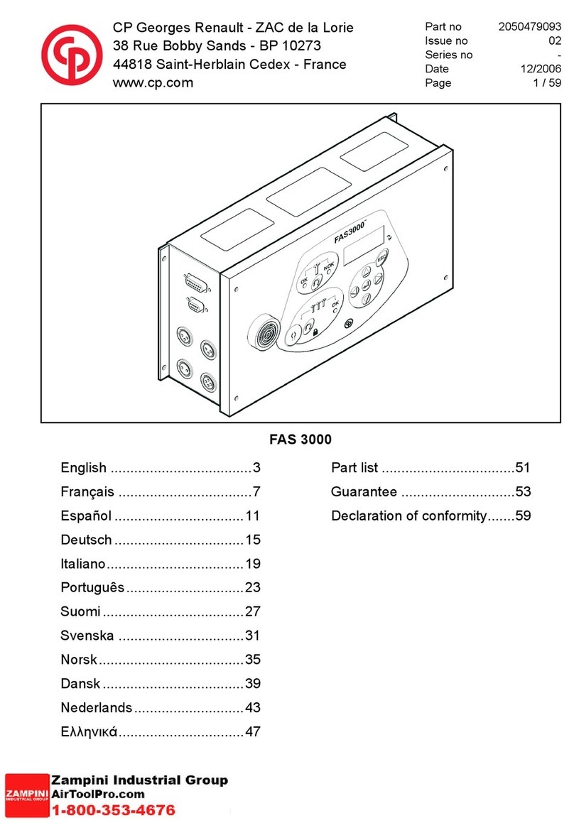
CP Desoutter FAS 3000 User manual

Part no
Issue no
Series no
Date
Page
CP Georges Renault - ZAC de la Lorie
38 Rue Bobby Sands - BP 10273
44818 Saint-Herblain Cedex - France
www.cp.com
2050479303
02
-
12/2006
1 / 218
English.................................... 3
Français................................ 21
Español................................. 39
Deutsch ................................ 57
Italiano .................................. 75
Português ............................. 93
Suomi ................................. 111
Svenska.............................. 129
Norsk .................................. 147
Dansk ................................. 165
Nederlands ......................... 183
ǼȜȜȘȞȚțȐ ............................. 201
FAS 3000 Flow Chart


FAS 3000 FLOW CHART
Part no 2050479303
Issue no 02
Series no -
Date 12/2006
Page 3 / 218
OPERATION
Normal operation of the FAS3000 is depicted below. On power-up, the unit will display a series of identifiers, code
revisions, etc. and then remain on the "count» window. The count window displays the current parameter set and the
current number of fasteners completed toward a GROUP. Other statistics are also available to the operator without a key
or password by pressing the arrow keys on the keypad. These options are described below.
Power-up sequence
Parameter set Count The count is the number of completed
fasteners in the batch. When the count equals
the batch, the count will go back to zero and a
GROUP ACCEPT output will be generated.
Product identification
Firmware revision numbers
Pressing the left or right arrows will
advance the display to the next or
previous screen respectively.
If this button is pressed, the
operator will be prompted for a
four-digit password before entering
the program menu.
During screen changes, a description of the
next value to be displayed will be shown
momentarily.
This number denotes the number of fasteners
to be completed to get a GROUP ACCEPT.
The max group is 255.
The TOTAL represents the number of
completed groups. If the total exceeds 9999,
the total will begin to scroll to show all five
digits. The max total is 65,535. After 65,535 is
reached, the total will reset to zero.
Number of sensors (1 or 2)

FAS 3000 FLOW CHART
Part no 2050479303
Issue no 02
Series no -
Date 12/2006
Page 4 / 218
SECURITY
The advanced settings and the GROUP RESET features of the FAS3000 are governed by a key-switch on the front of
the unit. Alternatively, a password may be used to enter the program menu or perform a GROUP RESET.
A four digit password may also be used to enter
the program menu or perform a GROUP
RESET.
The key-switch is used to unlock the advanced
features of the FAS3000.
When the key is in the locked position, the padlock-
shaped symbol will be illuminated, the program
menu will not be accessible, and the GROUP
RESET will not be available.
When the key is in the unlocked position, the
padlock-shaped symbol will not be illuminated and
all the afore mentioned features will be available.
This button can be used to enter the program
menu when unlocked, or to display the
password prompt when the unit is locked.

FAS 3000 FLOW CHART
Part no 2050479303
Issue no 02
Series no -
Date 12/2006
Page 5 / 218
SELECTING PARAMETER SETS
The FAS3000 has eight different parameter sets that can be used to store the qualification conditions for eight differing
fasteners. The parameter sets are referred to as sets A through H. The current parameter set can be selected using the
steps below:
Indicates the parameter set (A-H) that will
be used to qualify the fastener.
Use the arrow buttons on the keypad to
change parameter sets.
Press this key to switch to the selected
parameter set.
Press this key to exit the menu option
without making the change.
Allows external selection of parameter sets
with 15-pin sockets.
Do not use

FAS 3000 FLOW CHART
Part no 2050479303
Issue no 02
Series no -
Date 12/2006
Page 6 / 218
PROGRAM MENU
The program menu provides access to all the setting, features, and qualification parameters of the FAS3000. The
illustration below shows the location of each of the menu options. Each menu option will be expanded in detail on the
following pages.
These messages will each be displayed
momentarily to indicate to the operator that
he or she is now entering the program
menu.
Use the Up and DOWN buttons on the
keypad to navigate the PROGRAM
MENU.
Press this key to select an item to edit
from the menu.
Press this button to exit or "go back" from
a selected menu item. If the program
menu was accessed with the password,
press this key to exit the program menu
and return to normal operation. The
FAS3000 will again be locked, and a
password or key will be needed to re-
enter the program menu.

FAS 3000 FLOW CHART
Part no 2050479303
Issue no 02
Series no -
Date 12/2006
Page 7 / 218
AUTO-CALIBRATION
Auto-Calibration allows the operator to record the signature of a properly tightened fastener by which to qualify
succeeding fasteners. On the FAS3000, the process will be performed as follows:
Indicates the parameter set that will be
calibrated, i.e. parameter set A.
Press this key any time to exit the Auto-
Cal process.
These statements will repeat until the proper
button is pressed to continue to the next step.
or

FAS 3000 FLOW CHART
Part no 2050479303
Issue no 02
Series no -
Date 12/2006
Page 8 / 218
GROUPS
The group setting is the number of fasteners that need to be completed before the FAS3000 issues a GROUP-ACCEPT
output. If the sequencing feature is turned on, the group setting represents the number of fasteners that must be
completed before switching to the next parameter set in the sequence. A GROUP ACCEPT will be issued after the final
parameter set in the sequence is completed.
This number represents the number of fasteners in a GROUP.
One of the digits will be flashing. Use the up and down arrow
keys to increment or deincrement the flashing digit. Use the left
and right arrow keys to select the next digit for editing. The
maximum GROUP is 255.
Use these buttons to edit the next digit.
Press this key to save the change and exit
the menu option.
Press this key to exit the menu option
without making the change.
Use these buttons on the keypad to
increment or deincrement the flashing digit.

FAS 3000 FLOW CHART
Part no 2050479303
Issue no 02
Series no -
Date 12/2006
Page 9 / 218
CLEARING THE TOTAL
The total count is the number of GROUP ACCEPTs that have accumulated for the selected parameter set. The maximum
total is 65,535. The total can be cleared by selecting TOT in the program menu and following the steps below.
This message will scroll until the ENTER or ESC key is
pressed.
Press this key to set the total to zero and exit
the menu option.
Press this key to exit the menu option
without making the change.

FAS 3000 FLOW CHART
Part no 2050479303
Issue no 02
Series no -
Date 12/2006
Page 10 / 218
EXTERNAL SOLENOID DRIVER
The FAS3000 has a +24VDC output that can be enabled to shut off an air tool in the event of a NOK. The output can be
connected to an external solenoid to close an air valve, and in turn, disable the tool. The solenoid driver can be enabled
or disabled from the program menu as follows:
Press this key to save the change and exit
the menu option.
Press this key to exit the menu option
without making the change.
Use these buttons on the keypad to turn the
solenoid driver ON or OFF.

FAS 3000 FLOW CHART
Part no 2050479303
Issue no 02
Series no -
Date 12/2006
Page 11 / 218
SEQUENCING
The FAS3000 can be set to sequence through up to eight different parameter sets before issuing a GROUP ACCEPT.
Under SEQU in the program menu, the operator can choose the number of parameter sets to include in the sequence.
The FAS3000 will start in parameter set A. Upon completion of all the fasteners in group A, the FAS3000 will advance to
parameter set B and so on. The parameters in the sequence will have to be set up individually, i.e.: Auto-Cal, number of
fasteners in the group, etc. A GROUP RESET operation will also reset the sequence.
Press this key to save the change
and exit the menu option.
Press this key to exit the menu option
without making the change.
Use these buttons on the keypad to
select the number of parameter sets
in the sequence.

FAS 3000 FLOW CHART
Part no 2050479303
Issue no 02
Series no -
Date 12/2006
Page 12 / 218
BEEP ON ACCEPT
The FAS3000 will sound a double beep on GROUP ACCEPTS. This feature can be turned off in the program menu. The
FAS3000 will still beep on REJECTs.
Press this key to save the change and exit
the menu option.
Press this key to exit the menu option
without making the change.
Use these buttons on the keypad to turn the
"beep on ACCEPT" feature ON or OFF.

FAS 3000 FLOW CHART
Part no 2050479303
Issue no 02
Series no -
Date 12/2006
Page 13 / 218
GROUP TIMER
The FAS3000 is equipped with a group timer that is enabled and started by applying +24VDC to the Group Timer Start
input. The group timer is stopped by a GROUP ACCEPT. If the group timer is allowed to expire, the OK LED will flash on
and off, and the error code ER06 will be displayed until the GROUP is complete or the GROUP RESET is activated. The
Group Timer Start input must be maintained in order for the timer to run. Also, the group timer must be disabled and
enabled in order to restart the timer. The maximum group time is 99.9 seconds.
When the cycle timer expires, this message will appear on the
display until the GROUP is complete or a GROUP RESET is
activation.
Use these buttons to edit the next digit.
Press this key to save the change and exit
the menu option.
Press this key to exit the menu option
without making the change.
Use these buttons on the keypad to
increment or deincrement the flashing digit.

FAS 3000 FLOW CHART
Part no 2050479303
Issue no 02
Series no -
Date 12/2006
Page 14 / 218
TIME LIMITS
The FAS3000 uses four time limits to qualify the fastening cycle. These time limits are set by the Auto-Cal process, but
are also available for editing in the program menu. Each timer has a maximum value of 64.00 seconds.
Use these buttons to edit the next digit.
Press this key to save the change and exit
the menu option.
Press this key to exit the menu option
without making the change.
Use these buttons on the keypad to
increment or deincrement the flashing digit.

FAS 3000 FLOW CHART
Part no 2050479303
Issue no 02
Series no -
Date 12/2006
Page 15 / 218
THRESHOLDS
The FAS3000 uses two thresholds to qualify the fastening cycle. These thresholds will be set during the Auto-Cal process,
but are also available for editing in the program menu. The thresholds are displayed as percent of full scale
(approximately PSI). The values range from 0 to 99.
Use these buttons to edit the next digit.
Press this key to save the change and exit
the menu option.
Press this key to exit the menu option
without making the change.
Use these buttons on the keypad to
increment or deincrement the flashing digit.

FAS 3000 FLOW CHART
Part no 2050479303
Issue no 02
Series no -
Date 12/2006
Page 16 / 218
PASSWORD
The password can be used to access the program menu without using the key-switch. The FAS3000 will ship with a
default password that should be changed by the customer. The password consists of a four-digit number that can be
changed in the program menu. The password may also be used to perform a GROUP RESET.
Use these buttons to edit the next digit.
Press this key to save the change and exit
the menu option.
Press this key to exit the menu option
without making the change.
Use these buttons on the keypad to
increment or deincrement the flashing digit.

FAS 3000 FLOW CHART
Part no 2050479303
Issue no 02
Series no -
Date 12/2006
Page 17 / 218
ANALOG INPUT CHANNELS
The two analog input channels can be viewed if a trouble-shooting tool is needed. They are displayed as two percentages
from 0 to 99. These are the live readings from the two pressure trasducers.
Press this key to exit the menu option.

FAS 3000 FLOW CHART
Part no 2050479303
Issue no 02
Series no -
Date 12/2006
Page 18 / 218
NUMBER OF SENSORS
The FAS3000, version F1.11, B3.35 and higher, can be used with either 1 or 2 sensors. Select the number of sensors
via the "SENS" parameter. The number of sensors programmed is displayed at power up after the version screen.
Press this key to save the change and exit
the menu option.
Press this key to exit the menu option
without making the change.
Use these buttons on the keypad to select
the number of sensors

FAS 3000 FLOW CHART
Part no 2050479303
Issue no 02
Series no -
Date 12/2006
Page 19 / 218
RESET OPERATION
In the event of a NOK, an error code will be displayed and the beeper will sound. The FAS3000 will need to be reset in
order to continue operating. The RESET button will clear the error status and allow the operator to finish the group of
fasteners. If the solenoid driver is enabled, the solenoid output will no longer source +24VDC.
GROUP RESET OPERATION
In the event of a NOK, an error code will be displayed and the beeper will sound. The FAS3000 will need to be reset in
order to continue operating. The GROUP RESET will clear the error code and reset the count to zero. If sequencing is
enabled, the FAS3000 will also go back to the beginning of the sequence. If the solenoid driver is enabled, the solenoid
output will no longer source +24VDC.
In the event of a NOK, a cycle reset can be
performed by pressing this button.
In the event of a NOK, a GROUP RESET can be
performed by unlocking the unit with the key or
password and pressing this button.

FAS 3000 FLOW CHART
Part no 2050479303
Issue no 02
Series no -
Date 12/2006
Page 20 / 218
ERROR CODES
The FAS3000 has seven error codes. The function and description of each error code are described below. In the event
of a NOK, the error code will be displayed and the beeper will sound until the operator performs a RESET. If the solenoid
driver is enabled, the solenoid output will source +24VDC until a RESET is performed.
"Screw Pre tightened".
This occurs if the clutch operates immediately within time t0.
Typical causes - Fastener is already tightened or cross threaded. The operator has "blipped" the
trigger/lever.
"Clutch operated too early".
This occurs if the clutch operates before time t1 and indicates the clutch has operated too early.
Typical causes: Screw is too short, has become cross threaded or is too tight. (i.e. Component
characteristics have changed, possible batch related problem), hole is not deep enough, screw too
long in a blind hole.
This problem could also occur if the air supply pressure has increased since the tool was last set
up. Alternatively, if the tool has just been serviced and or torque re-adjusted.
"Clutch operated too late".
This occurs if the clutch operates after time t2. Typical causes: Screw is too long in a through hole,
is too small a diameter, no thread, hole too large. It can also occur if the air supply pressure has
dropped and or the tool is becoming slow. Alternatively, if the tool has just been serviced and or
torque re-adjusted.
"Trigger/lever released too quickly after clutch operated".
This occurs if the trigger/lever is released too quickly after the clutch has operated. The check is
carried out with time t3.
Typical causes: Operator has released the trigger/lever too quickly after the clutch has operated
(But for a greater time then Timer t0).
Operators should be made aware of this feature.
"Trigger released before clutch operates".
This occurs if the trigger/lever is released before time limit t2 and before the clutch has operated.
Typical causes: Operator has released the trigger too early. (i.e. due to high ambient noise, may
sense that the tool has tightened and releases the trigger/lever).
Operators must wait for the Green OK LED to illuminate before releasing the trigger.
Problem with sensors, electrical Signals did not change.
This occurs if there is no change in the trigger/lever or clutch signals at the start of the cycle.
Typical causes: Defective sensor, broken sensor cable, tool requires repair or service.
In extreme cases, could be due to poor air supply to the tool.
When the cycle timer expires, this message will appear on the display until the GROUP is
complete or a GROUP RESET is activated.
Other manuals for Desoutter FAS 3000
1
Table of contents
Languages:
Other CP Power Tools manuals

