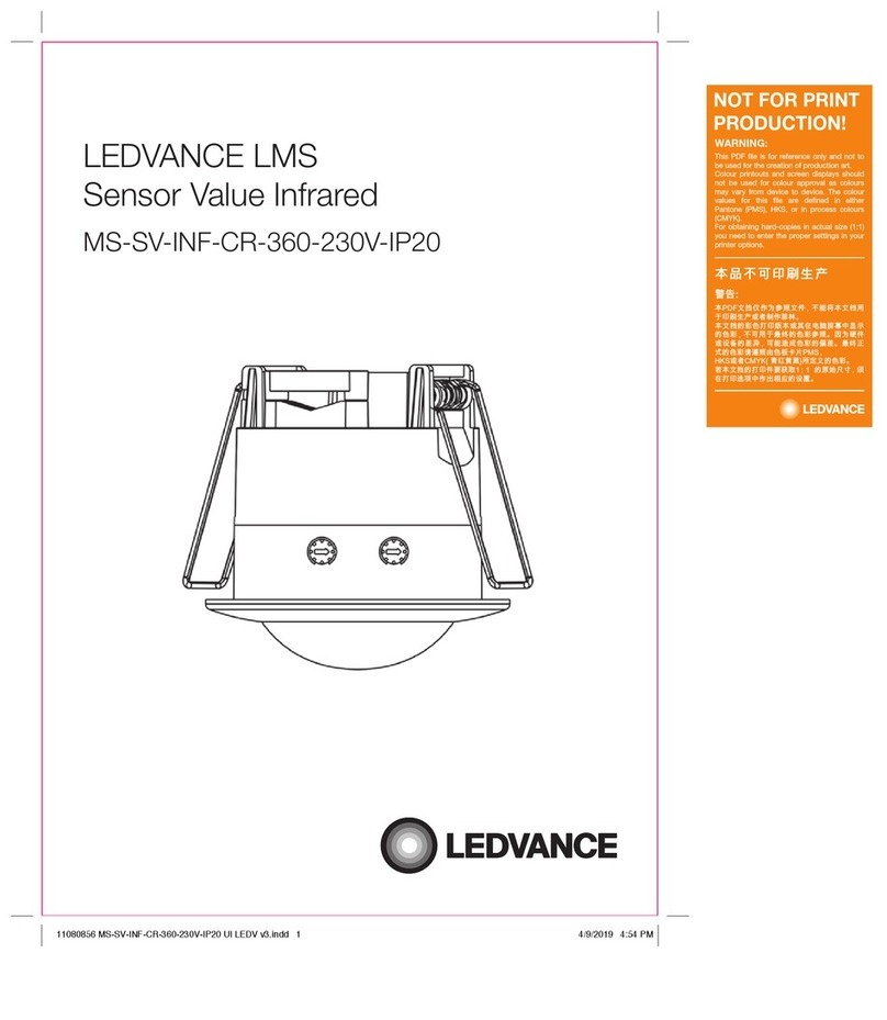
Ledvance MS-SV-INF-CR-A-360-230V-IP20 User manual

LEDVANCE LMS
Sensor Value Infrared
MS-SV-INF-CR-A-360-230V-IP20
WARNING:
NOT FOR PRINT
PRODUCTION!
This PDF file is for reference only and not to
be used for the creation of production art.
Colour printouts and screen displays should
not be used for colour approval as colours
may vary from device to device. The colour
values for this file are defined in either
Pantone (PMS), HKS, or in process colours
(CMYK).
For obtaining hard-copies in actual size (1:1)
you need to enter the proper settings in your
printer options.
㮍⥠⋀⢏⠐⛛䤢⍗
弜⣩
㦻3')㠖㖰⅔⇫♑䏶㠖ↅ᧨ ₜ厌⺕㦻㠖㫲䞷
ℝ◿Ⓠ䞮ℶ㒥劔Ⓟ⇫嚁㨦ᇭ
㦻㠖㫲䤓ㇸ唁㓢◿䓗㦻㒥␅⦷䟄厠⻞ヤ₼㣍䯉
䤓唁ㇸ᧨ₜ♾䞷ℝ㦏兗䤓唁ㇸ♑䏶ᇭ⥯䫻ↅ
㒥幍䤓ぽ㆑᧨♾厌抯㒟唁ㇸ䤓⋞ぽᇭ㦏兗㷲
㆞䤓唁ㇸ庆挄䏶䟀唁㨎◰䓖306᧨
+.6㒥劔&0<.槡儱煓煠`㓏⸩䤓唁ㇸᇭ
啴㦻㠖㖰䤓㓢◿ↅ尐噆♥ 䤓☮ⱚ⻉⺇᧨權
⦷㓢◿折欈₼⇫⒉䦇ㄣ䤓幍函ᇭ
11080850 MS-SV-INF-CR-A-360-230V-IP20 UI LEDV v3.indd 1 4/9/2019 4:51 PM

LEDVANCE LMS Sensor Value Infrared
black
score dimension 148 x 210 mm
2
Product Features:
a. Infrared motion sensor with integrated photocell sensing function can help to save power consumption via turn
on and turn off the power according to its setting; It detects human motion within its detection range.
b. Infrared motion sensor cannot receive the induction if there is glass, wood or metal materials in between within
detection range;
c. Selectable time delay period from 10 seconds to 15 minutes via knob switch;
d. Selectable daylight sensing level from 3 lux to 2000 lux via knob switch.
Product Specification:
a. Detection method: Infrared motion sensor with photocell integrated
b. Ambient temperature: -20~+40°C
c. Power Input: 220-240V/AC
d. Input Frequency: 50/60Hz
e. Detection Range: 360°
f. Installing Height: 2.2~4m
g. Ambient Light (Selectable): <10-2000LUX
h. Time-Delay (Selectable):
• Min.:10sec±3sec;
• Max.:15min±3min;
i. Nominal Power Consumption: 0.9W
j. Transmission Power: <10mW
k. Maximum Rated Load:
• 1200W (incandescent lamp)
• 300W (energy-saving / led-lamp)
l. Detection Motion Speed: 0.6~1.5m/s
m. Detection Distance (selectable): 8m max. (<24°C)
Selectable Functions via Knob:
a. Selectable daylight luminance level: Sensing luminance level can work both in the daytime and at night when
you select the “sun” position (max) via knob. It can work in the environment that the luminance is less than 3LUX
when it is adjusted to the “3” position (min). As for the adjustment pattern, please refer to the testing pattern.
b. Time-Delay is added continually: When sensor receives the second induction signal after the first induction, it
will perform the time delay period again according to the 2nd induction.
c. Selective time delay period length: It can be set according to the consumer’s desire. The minimum delay period
is 10sec±3sec. The maximum delay period is 15min±3min.
Installation Guide and product diagram
INSTALLATION ADVICE:
As the detector responds to changes of temperature, please avoid the following situations:
a. Avoid directing the detector towards objects with highly reflective surfaces, such as mirrors etc.
b. Avoid mounting the detector near heat sources, such as heating vents, air conditioning units, light etc.
c. Avoid directing the detector towards objects that may move in the wind, such as curtains, tall plants etc.
Step 1 Step 2 Step 3
Good Sensitivity Poor SensitivitySensitivity
11080850 MS-SV-INF-CR-A-360-230V-IP20 UI LEDV v3.indd 2 4/9/2019 4:51 PM

LEDVANCE LMS Sensor Value Infrared
3
black
score dimension 148 x 210 mm
How to Install:
a. Switch off the power.
b. Swing the plastic cover a little and adjust time and LUX knob.
c. Unload the transparent vinyl cover which is at the bottom of the sensor.
d. Loose the screws in the connection terminal, and then connect the power lead to connection terminal of sensor
according to wire connection diagram.
e. Install back the transparent vinyl cover into the original location.
f. Fold the metal spring of the sensor upwards until they are in “I” position with sensor, and then put the sensor
into the hole or installation box with 61.5mm cut-out hole on the ceiling. Releasing the spring, the sensor will be
set in this installation position.
g. After finishing installing, turn on the power and then test it.
Wire Connection diagram:
(See the right figure)
SENSOR INFORMATION
Product Features:
a. Infrared motion sensor with integrated photocell sensing function can help to save power consumption via turn
on and turn off the power according to its setting; It detects human motion within its detection range.
b. Infrared motion sensor cannot receive the induction if there is glass, wood or metal materials in between within
detection range;
c. Selectable time delay period from 10 seconds to 15 minutes via knob switch;
d. Selectable daylight sensing level from 3 lux to 2000 lux via knob switch.
Product Specification:
a. Detection method: Infrared motion sensor with photocell integrated
b. Ambient temperature: -20~+40°C
c. Power Input: 220-240V/AC
d. Input Frequency: 50/60Hz
e. Detection Range: 360°
f. Installing Height: 2.2~4m
g. Ambient Light (Selectable): <10-2000LUX
h. Time-Delay (Selectable):
• Min.:10sec±3sec;
• Max.:15min±3min;
i. Nominal Power Consumption: 0.9W
j. Transmission Power: <10mW
k. Maximum Rated Load:
• 1200W (incandescent lamp)
• 300W (energy-saving / led-lamp)
l. Detection Motion Speed: 0.6~1.5m/s
m. Detection Distance (selectable): 8m max. (<24°C)
Selectable Functions via Knob:
a. Selectable daylight luminance level: Sensing luminance level can work both in the daytime and at night when
you select the “sun” position (max) via knob. It can work in the environment that the luminance is less than 3LUX
when it is adjusted to the “3” position (min). As for the adjustment pattern, please refer to the testing pattern.
b. Time-Delay is added continually: When sensor receives the second induction signal after the first induction, it
will perform the time delay period again according to the 2nd induction.
c. Selective time delay period length: It can be set according to the consumer’s desire. The minimum delay period
is 10sec±3sec. The maximum delay period is 15min±3min.
Installation Guide and product diagram
INSTALLATION ADVICE:
As the detector responds to changes of temperature, please avoid the following situations:
a. Avoid directing the detector towards objects with highly reflective surfaces, such as mirrors etc.
b. Avoid mounting the detector near heat sources, such as heating vents, air conditioning units, light etc.
c. Avoid directing the detector towards objects that may move in the wind, such as curtains, tall plants etc.
Step 1 Step 2 Step 3
Testing Before Using:
a. Turn the TIME knob anti-clockwise to the minimum (10s). Turn the LUX
knob clockwise to the maximum (sun).
b. Switch on the power; the sensor and its connected lamp will have no signal
at the beginning. After warm-up 30sec, the sensor can start work. If the
sensor receives the induction signal, the lamp will turn on. While there is
no another induction signal any more, the load should stop working within
10sec±3sec and the lamp would turn off.
c. Turn LUX knob anti-clockwise on the minimum (3). If the ambient light is more than 10LUX, the sensor would
not work, and the lamps stop working too. If the ambient light is less than 10LUX (darkness), the sensor would
work. Under no induction signal condition, the sensor should stop working within 10sec±3sec.
Note: When testing in daylight, please turn LUX knob to (SUN) position, otherwise the sensor lamp could not
work! If the load is >60W, the distance between lamp and sensor should be longer than 60cm.
4m 4m
Max:4m Max:4m
360°
2.2-4m
11080850 MS-SV-INF-CR-A-360-230V-IP20 UI LEDV v3.indd 3 4/9/2019 4:51 PM

C10449058
G11080850
2019-09-04
Basic Malfunctions Detection and Troubleshooting
a. If the load cannot work:
a) Please check the power and the load.
b) Please check if the indicator light is turned on after sensing or not? If yes, please check the load.
c) If the indicator light does not turn on after sensing, please check if the working light corresponds to the
ambient light.
d) Please check if the working voltage corresponds to the power source.
e) Please check if there is any glass, wood or metal material in the sensor detection range which block the
sensor from receiving induction signal.
b. The sensitivity is poor:
a) Please check if in front of the detection window there are any obstacles that disturb the signals receiving.
b) Please check the ambient temperature.
c) Please check if the signals source is in the detection fields.
d) Please check if the installation height is within the indicated height level.
e) e. Please check if the moving orientation is correct.
c. The sensor can’t turn off the load automatically:
a) Please check if there are continual signals in the detection fields.
b) Please check if the time delay is set to the longest.
c) Please check if the power input is following the instruction.
d) Please check if the environment temperature changes a lot due to its installation location is very close to air
conditioners or central heater.
Warnings:
a. The product should be installed by licensed electricians.
b. The product should not be installed on any moving objects or surface.
c. Please do not put any obstacles or unrest objects in front of the detection window to influence the detection.
d. Please do not put the sensor near the area which is having tremendous changes of temperature such as air
conditioner or central heater.
e. Please don’t open the case after installation.
www.ledvance.com.au
LEDVANCE Pty Ltd
ABN 34 050 103 181
Suite 2.1A
394 Lane Cove Road
Macquarie Park NSW 2113,
Australia
Ph +61 29481 8399 / 1300 467 726
www.ledvance.com.au
11080850 MS-SV-INF-CR-A-360-230V-IP20 UI LEDV v3.indd 4 4/9/2019 4:51 PM
Table of contents
Other Ledvance Security Sensor manuals
Popular Security Sensor manuals by other brands

System Sensor
System Sensor SpectrAlert DS2475WAR Installation and maintenance instructions

SICK
SICK i200 Lock operating instructions

Reliable
Reliable J168 manual

Federal Signal Corporation
Federal Signal Corporation SENTRY Installation and maintenance instructions

Osko
Osko Edge Air 1417 User & service manual

Siemens
Siemens Cerberus CS1140 Commissioning