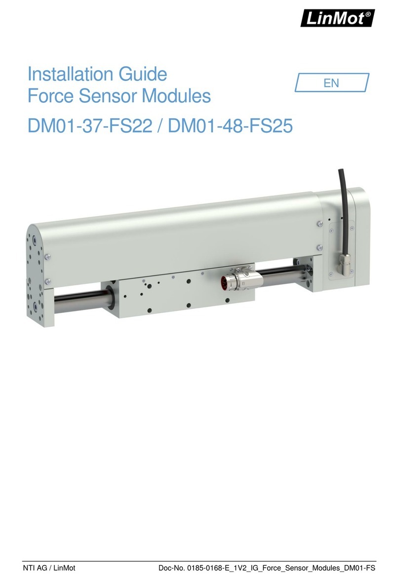
LinMot DM01-23-FS User manual

NTI AG / LinMot Doc-No. 0185-0168-E_1V3_IG_Force_Sensor_Modules_DM01-FS
Installation Guide
Force Sensor Modules
EN
DM01-23-FS / DM01-37-FS / DM01-48-FS

Installation Guide Force Sensor Modules EN
Page 2 / 25 DM01-23-FS / DM01-37-FS / DM01-48-FS NTI AG / LinMot
Content
1General Information ................................................................................................................................. 4
1.1 Introduction........................................................................................................................................ 4
1.2 Explanation of Symbols..................................................................................................................... 4
1.3 Qualified Personnel ........................................................................................................................... 4
1.4 Liability............................................................................................................................................... 4
1.5 Copyright............................................................................................................................................ 4
2Safety Instructions................................................................................................................................... 5
3Installation Instructions........................................................................................................................... 7
3.1 Operating Conditions......................................................................................................................... 7
3.2 Assembling Instruction Force Sensor DM01-23-FS.......................................................................... 7
3.3 Assembling Instruction Force Sensor DM01-37-FS.......................................................................... 8
3.4 Assembling Instruction Force Sensor DM01-48-FS.......................................................................... 9
3.5 Adjusting the Length of the Cable Conduit...................................................................................... 10
3.5.1 DM01-23...................................................................................................................................... 10
3.5.2 DM01-37...................................................................................................................................... 10
3.5.3 DM01-48x150.............................................................................................................................. 11
3.5.4 DM01-48x240.............................................................................................................................. 11
3.6 Material Data ................................................................................................................................... 11
4Electrical Connection............................................................................................................................. 11
4.1 Sensor Cable................................................................................................................................... 11
4.1.1 Technical Data............................................................................................................................. 11
4.2 Pin Assignment Sensor Cable......................................................................................................... 12
4.3 Force Sensor Module Wiring........................................................................................................... 12
4.3.1 Connection to C11x0 and C12xx Servo Drives........................................................................... 12
4.3.2 Connection to C1252 Servo Drive............................................................................................... 13
5Commissioning....................................................................................................................................... 13
5.1 Initial Commissioning of the Force Sensor...................................................................................... 13
5.1.1 Technology Function Force Control" Software Package............................................................. 13
5.1.2 Setting the Parameters for Force Control at C12x0.................................................................... 13
5.1.3 Initial Testing of a Force Sensor.................................................................................................. 14
5.2 Special LinMot-Talk Functions......................................................................................................... 15
5.2.1 Tare Function............................................................................................................................... 15
5.2.2 Speed limiter function.................................................................................................................. 16
6Accessories ............................................................................................................................................ 17
6.1 Extension Cables............................................................................................................................. 17
6.1.1 Extension Cable for Connection to C11x0 and C12xx Servo Drives .......................................... 17
6.1.2 Extension Cable for Connection to Servo Drive C1252 .............................................................. 17
7Maintenance and Test Instructions...................................................................................................... 17
7.1 Maintenance.................................................................................................................................... 17
7.2 Cleaning........................................................................................................................................... 18
7.3 Lubrication ....................................................................................................................................... 18
7.4 Calibration........................................................................................................................................ 18

Installation Guide Force Sensor Modules EN
NTI AG / LinMot DM01-23-FS / DM01-37-FS / DM01-48-FS Page 3 / 25
8Transport and storage........................................................................................................................... 18
9Dimensions............................................................................................................................................. 19
9.1 Force Sensor Module DM01-23-FS................................................................................................. 19
9.2 Force Sensor Module DM01-37-FS................................................................................................. 21
9.3 Force Sensor Module DM01-48-FS................................................................................................. 22
10 EU Declaration of Conformity CE-Marking.......................................................................................... 23
11 UK Declaration of Conformity UKCA-Marking .................................................................................... 24

Installation Guide Force Sensor Modules EN
Page 4 / 25 DM01-23-FS / DM01-37-FS / DM01-48-FS NTI AG / LinMot
1 General Information
1.1 Introduction
This manual includes instructions for the assembly, installation, maintenance, transport, and storage of
DM01 force sensor modules. The document is intended for electricians, mechanics, service technicians, and
warehouse staff.
Read this manual before using the product and observe the general safety instructions and those in the
relevant section at all times.
Keep these operating instructions in an accessible place and make them available to the personnel
assigned.
1.2 Explanation of Symbols
Triangular warning signs warn of danger.
Round command symbols tell what to do.
1.3 Qualified Personnel
All work such as installation, commissioning, operation and service of the product may only be carried out by
qualified personnel.
The personnel must have the necessary qualifications for the corresponding activity and be familiar with the
installation, commissioning, operation and service of the product. The manual and in particular the safety
instructions must be carefully read, understood and observed.
1.4 Liability
NTI AG (as manufacturer of LinMot and MagSpring products) excludes all liability for damages and
expenses caused by incorrect use of the products. This also applies to false applications, which are caused
by NTI AG's own data and notes, for example in the course of sales, support or application activities. It is the
responsibility of the user to check the data and information provided by NTI AG for correct applicability in
terms of safety. In addition, the entire responsibility for safety-related product functionality lies exclusively
with the user.Product warranties are void if products are used with stators, sliders, servo drives or cables not
manufactured by NTI AG unless such use was specifically approved by NTI AG.
NTI AG’s warranty is limited to repair or replacement as stated in our standard warranty policy as described
in our "terms and conditions" previously supplied to the purchaser of our equipment (please request copy of
same if not otherwise available). Further reference is made to our general terms and conditions.
1.5 Copyright
This work is protected by copyright.
Under the copyright laws, this publication may not be reproduced or transmitted in any form, electronic or
mechanical, including photocopying, recording, microfilm, storing in an information retrieval system, not even
for training purposes, or translating, in whole or in part, without the prior written consent of NTI AG.
LinMot® and MagSpring® are registered trademarks of NTI AG.

Installation Guide Force Sensor Modules EN
NTI AG / LinMot DM01-23-FS / DM01-37-FS / DM01-48-FS Page 5 / 25
2 Safety Instructions
Contusions
Sliders contain neodynium magnets and have a strong attractive force.
Careless handling could cause fingers or skin to become pinched between two sliders.
This may lead to contusions, bruises, and bone fractures.
When handling sliders, wear thick protective gloves and keep a minimum distance between
sliders. Refer to the "Minimum distance from slider" section for minimum distance.
To reduce the risk of injury, never more than one slider should be held or transported by the
same person without packaging.
Pacemaker / Implanted Heart Defibrillator
Sliders could affect the functioning of pacemakers and implanted heart defibrillators. For the
duration of a strong approach to a magnetic field, these devices switch into test mode and
will not function properly.
•If you wear one of those devices keep the following minimum distances between the
pacemaker / defibrillator and slider:
- Min. 250 mm (10ʺ) for slider Ø 27 mm and 28 mm (PL01-27 / 28 / PL10-28)
- Min. 150 mm (6ʺ) for slider Ø 19 mm and 20 mm (PL01-19 / 20)
- Min. 100 mm (4ʺ) for slider Ø 12 mm (PL01-12)
•Inform others who wear these devices to comply with these minimum distances!
Caution - Risk of Electric Shock !
Before working, make sure that there are no high voltages.
Fast-moving Machine Parts
The sliders of LinMot linear motors are fast-moving machine parts. All necessary
precautions must be taken to prevent persons approaching the moving elements during
operation (provide covers, guards, etc.).
Automatic Restart
The motors can start automatically under certain cricumstances!
If necessary, a corresponding warning symbol must be provided and protection against
entering the hazardous area or a suitable safe electronic disconnection must be provided!
Risk of Injury due to a Defect or Fault
For areas where a defect or fault can result in substantial property damage or even serious
personal injury, additional external precautions must be taken or devices must be installed
to ensure safe operation even if a defect or fault occurs (eg. suitable safe electronic
disconnection, mechanical interlocks, barriers, etc.).
Magnetic Field
Magnets integrated in the sliders produce a strong magnetic field. They could damage TVs,
laptops, computer hard drives, credit and ATM cards, data storage media, mechanical
watches, hearing aids, and speakers.
•Keep magnets away from devices and objects that could be damaged by strong
magnetic fields.
•For the above mentioned objects, keep a minimum distance as described in the
"Pacemaker / implanted defibrillator" section.
•For non-anti-magnetic watches, keep the double minimum distance.

Installation Guide Force Sensor Modules EN
Page 6 / 25 DM01-23-FS / DM01-37-FS / DM01-48-FS NTI AG / LinMot
Combustibility
When machining magnets, the drilling dust could easily ignite.
Machining the sliders and the magnets they contain is not permitted.
Burn Hazard
During operation the slider can become hotter than 100 °C, which can cause burns if
touched. All necessary precautions (e.g. covers, casing, etc.) must be taken to prevent
contact with persons in the vicinity of the slider during operation.
Grounding
All metal parts that are exposed to contact during any user operation or servicing and likely
to become energized shall be reliably connected to the means for grounding.
Mechanical Handling
Neodymium magnets are brittle and heat-sensitive.
Machining the sliders and the magnets they contain is not permitted.
•Colliding magnets could crack. Sharp splinters could be catapulted for several meters
and cause eye injury.
•By machining the sliders, heat would result which demagnetizes the magnets.
Slider
Linear motor sliders consist of a high-precision, thin-walled stainless steel tube in which the
neodymium magnets are housed. The LinMot sliders should be handled with care.
Avoid contact with other sliders or iron parts as this can damage the magnets and the slider
surface. Do not grip the sliders with pliers, as this can also damage the surface. Do not use
sliders which are already damaged on the surface (scratches, deformation, etc.). This can
cause further damage to the stator.
Effects on People
According to the current level of knowledge, magnetic fields of permanent magnets do not
have a measurable positive or negative effect on people. It is unlikely that permanent
magnets constitute a health risk, but it cannot be ruled out entirely.
•For your own safety, avoid constant contact with magnets.
•Store large magnets at least one meter away from your body.
Temperature Resistance
Keep slider away from unshielded flame or heat.
Temperature above 120°C will cause demagnetization.

Installation Guide Force Sensor Modules EN
NTI AG / LinMot DM01-23-FS / DM01-37-FS / DM01-48-FS Page 7 / 25
3 Installation Instructions
3.1 Operating Conditions
•The ambient temperature limit is: 0 °C...80 °C (reduced accuracy)
•The nominal service temperature is: 5 °C...45 °C
•Max. Installation altitude: The
maximum installation altitude is 4,000 m a.s.l.
Above 1,000 m, a derating of
1 °C per 100 m must be taken into account for
air cooling.
3.2 Assembling Instruction Force Sensor DM01-23-FS
Be sure to observe the safety instructions in chapter 2 during assembly!
1. Set mounting side
The force sensor module can be mounted on
either side of the linear module.
Due to the mechanical connection of
the slider, it is recommended to mount
the force sensor on the connector side
of the linear module. On this side, the
force is applied directly via a fixed
bearing.
2. Mount force sensor module
Apply Loctite 243 threadlocker to the threaded
holes of the force sensor module.
Then fix the module to the front plate of the
linear module with the four screws.
Tightening torque: 2.6 Nm
The measuring amplifier box can be placed
externally in the machine. The IP protection
class of the amplifier is IP63.

Installation Guide Force Sensor Modules EN
Page 8 / 25 DM01-23-FS / DM01-37-FS / DM01-48-FS NTI AG / LinMot
3. Wiring the force sensor module
The sensor cable is guided in a cable conduit.
The cable conduit can be shortened as required
(see chapter 3.5). For mounting, 2 brackets are
supplied which can be mounted on the DM01
linear module (see illustration). A drive-side
open-end extension cable is recommended for
connecting the force sensor module to servo
drives of the C11x0 and C12xx series (see
chapter Accessories). The wiring diagram is
shown in chapter 4.3.
Only connect or disconnect the sensor
cable when there is no voltage at the
servo drive!
3.3 Assembling Instruction Force Sensor DM01-37-FS
Be sure to observe the safety instructions in chapter 2 during assembly!
1. Set mounting side
The force sensor module can be mounted on
either side of the linear module.
Due to the mechanical connection of
the slider, it is recommended to mount
the force sensor on the connector side
of the linear module. On this side, the
force is applied directly via a fixed
bearing.
2. Mount force sensor module
Apply Loctite 243 threadlocker to the threaded
holes of the force sensor module.
Then fix the module to the front plate of the
linear module with the four screws.
Tightening torque: 8.6 Nm

Installation Guide Force Sensor Modules EN
NTI AG / LinMot DM01-23-FS / DM01-37-FS / DM01-48-FS Page 9 / 25
3. Wiring the force sensor module
The sensor cable is guided in a cable conduit.
The cable conduit can be shortened as required
(see chapter 3.5). For mounting, 2 brackets are
supplied which can be mounted on the DM01
linear module (see illustration). A drive-side
open-end extension cable is recommended for
connecting the force sensor module to servo
drives of the C11x0 and C12xx series (see
chapter Accessories). The wiring diagram is
shown in chapter 4.3.
Only connect or disconnect the sensor
cable when there is no voltage at the
servo drive!
3.4 Assembling Instruction Force Sensor DM01-48-FS
Be sure to observe the safety instructions in chapter 2 during assembly!
1. Dismantle cover
2. Set mounting side
The force sensor module can be mounted on
either side of the linear module.
Due to the mechanical connection of
the slider, it is recommended to mount
the force sensor on the connector side
of the linear module. On this side, the
force is applied directly via a fixed
bearing.

Installation Guide Force Sensor Modules EN
Page 10 / 25 DM01-23-FS / DM01-37-FS / DM01-48-FS NTI AG / LinMot
3. Mount force sensor module
Apply Loctite 243 threadlocker to the threaded
holes of the force sensor module.
Then fix the module to the front plate of the
linear module with the four screws.
Tightening torque: 8.6 Nm
Finally, refit the cover.
4. Wiring the force sensor module
The sensor cable is guided in a cable conduit.
The cable conduit can be shortened as required
(see chapter 3.5). For mounting, 2 brackets are
supplied which can be mounted on the DM01
linear module (see illustration). A drive-side
open-end extension cable is recommended for
connecting the force sensor module to servo
drives of the C11x0 and C12xx series (see
chapter Accessories). The wiring diagram is
shown in chapter 4.3.
Only connect or disconnect the sensor
cable when there is no voltage at the
servo drive!
3.5 Adjusting the Length of the Cable Conduit
All force sensors are delivered with a ready-mounted cable conduit. It is recommended that this is shortened
to an appropriate length. This length is based on the stroke and is measured from the beginning of bracket 1
to the end of bracket 2.
3.5.1 DM01-23
Stroke [mm]
60
100
160
220
290
350
Recommended length
of the cable conduit
[mm]
385
415
475
535
605
665
3.5.2 DM01-37
Stroke [mm]
95
195
295
395
495
595
Recommended length
of the cable conduit
[mm]
505
605
705
805
905
1005

Installation Guide Force Sensor Modules EN
NTI AG / LinMot DM01-23-FS / DM01-37-FS / DM01-48-FS Page 11 / 25
3.5.3 DM01-48x150
Stroke [mm]
95
125
185
275
305
395
485
575
Recommended length
of the cable conduit
[mm]
475
505
565
655
685
775
865
955
3.5.4 DM01-48x240
Stroke [mm]
95
185
305
395
485
Recommended length
of the cable conduit
[mm]
565
595
655
865
955
3.6 Material Data
Component
Material
Housing
Anodised aluminium
Front plate
Anodised aluminium
Seal
NBR 70
Cable connector
Brass nickel plated
Sensor cable (sheath)
PUR
Cable conduit
Polyamide
4 Electrical Connection
4.1 Sensor Cable
Only connect or disconnect the sensor cable when there is no voltage at the servo drive!
Use original LinMot cables for sensor wiring! Self-assembled cables must be checked
carefully before commissioning! Incorrect sensor wiring can damage the sensor and / or the
servo drive!
The force sensor has a direct cable outlet of 2 m length. Depending on the drive family, the force sensor can
be connected directly to the servo drive or extended if required. Extension cables are listed in the
"Accessories" chapter.
4.1.1 Technical Data
High-Flex Cable
Cable name
KS14-06
Minimum bending radius for
fixed installation
18 mm
Minimum bending radius
when moving
50 mm (2 in)
No torsion
Shielding
simply
Length
2m
Approval
UL/CSA
Material wire insulation
TPE
Material cable sheath
PUR
Oil resistance
very good according to EN 50363-10-2 + VDE 0207-363-10-2
Chemical resistance
(to acids, alkalis, solvents,
hydraulic fluid)
good
Burning behaviour
Flame retardant and self-extinguishing

Installation Guide Force Sensor Modules EN
Page 12 / 25 DM01-23-FS / DM01-37-FS / DM01-48-FS NTI AG / LinMot
4.2 Pin Assignment Sensor Cable
Only connect or disconnect the sensor cable when there is no voltage at the servo drive!
Use original LinMot cables for sensor wiring! Self-assembled cables must be checked
carefully before commissioning! Incorrect sensor wiring can damage the sensor and / or the
servo drive!
Pin assignment
Force sensor
PIN
Core colour
Sensor cable
Supply GND
1
white
Do not connect
2
n/a
AGND
3
pink
Do not connect
4
n/a
Force+
5
grey
Supply 24V
6
brown
Do not connect
7
n/a
Motlink P
8
green
Force-
9
yellow
Connector housing
Shield
n/a
Connector scheme
(Cable outlet)
PIN 9 (power -) and PIN 1 (supply ground) are internally galvanically isolated and must not
be connected to each other.
4.3 Force Sensor Module Wiring
The type of connection between the force sensor and the servo drive depends on the LinMot servo drive.
4.3.1 Connection to C11x0 and C12xx Servo Drives
The following diagram shows the connection of the force sensor to terminal X4 LOGIC SUPPLY CONTROL
of the LinMot servo drive.

Installation Guide Force Sensor Modules EN
NTI AG / LinMot DM01-23-FS / DM01-37-FS / DM01-48-FS Page 13 / 25
4.3.2 Connection to C1252 Servo Drive
The DSUB connector of the force sensor can be connected directly to the C1252 Drive via the X3 MOT
SENSOR interface.
5 Commissioning
5.1 Initial Commissioning of the Force Sensor
An optionally mounted force sensor is a high-precision measuring device and must be
handled accordingly. Incorrect handling, e.g. driving in to the mechanical stop, will cause
collisions that may exceed the maximum force defined in the data sheet. Incorrect handling
of the measuring device can damage the sensors.
It is strongly recommended to carefully follow the initial commissioning steps and test the
correct functioning of the measuring device before using it in real application.
5.1.1 Technology Function Force Control" Software Package
If a closed control loop is to be implemented via a sensor (force control of a motor by means of sensor
feedback to the LinMot Drive), it is mandatory to order the "TF Force Control" software package (art. no.:
0150-2503).
Without this software package, it is not possible to control a specific force or to use the drive commands of
the "TF Force Control" software package.
If only the signal of the force sensor is evaluated (PLC or LinMot Drive), the software package can be
dispensed with.
5.1.2 Setting the Parameters for Force Control at C12x0
Logged into the drive, you will find all the parameters to be set in
the LinMot-Talk software under the path "Parameters -> Motion
Control SW -> Protected Technology Functions -> Analogue Force
Feedback Control".
Parameter Tree: Input Selection
Please select the following setting under "Input Selection":
•Input Selection (UPID 150Fh) = Diff Analog Input On X4.10/X4.11
Parameter Tree: Analogue Force Feedback Config

Installation Guide Force Sensor Modules EN
Page 14 / 25 DM01-23-FS / DM01-37-FS / DM01-48-FS NTI AG / LinMot
Due to the definition of the DEFAULT positive direction of the stroke, it is recommended to
invert the +-10VDC signal via software. This means that for the parameter "0V/-10V Force"
the positive maximum value and for the parameter "+10V Force" the negative maximum
value of the force sensor is set.
By changing the direction of the stroke, the setting of the parameters "0V/-10V force" and
"10V force" must also be changed.
•0V/-10V Force (UPID 1501h) = Positive maximum value (e.g. 500 N)
•10V Force (UPID 1502h) = Negative maximum value (e.g. -500 N)
•Speed Filter Time (UPID 150Ah) = 1000µs
•Acceleration Filter Time (UPID 150Dh) = 1000µs
Parameter Tree: Force Control Parameters
The parameters for the force control loop are set here. A PID controller, a few pre-control parameters (FF
parameters) and a parameter for limiting the maximum control current (Force Ctrl Max Current) are available
for this purpose.
Work with a pure I controller at the beginning to prevent the motor from oscillating during
torque control.
Limit the maximum control current in order to avoid any possible damages during
commissioning.
5.1.3 Initial Testing of a Force Sensor
It is recommended to perform an initial test of a sensor with the LinMot talk variables before reaching the
operating state.
1. Log in to the Drive with the LinMot Talk software and open the "control panel".
2. Switch on the motor with the "Control Word" (Switch On). The motor remains in position control
mode.
3. Add the variables "Target Force" and "Measured Force" (MC SW Force Control) via the "Add
Variable" button.

Installation Guide Force Sensor Modules EN
NTI AG / LinMot DM01-23-FS / DM01-37-FS / DM01-48-FS Page 15 / 25
4. Now gently push or pull the linear axis. The variable "measured force" should rise or fall according to
the variable "Motor Current".
•If no change can be detected within the Measured Force variable, check the wiring of
the sensor.
•If the value of the variable "Measured Force" changes in a different direction than the
variable "Motor Current" shows, please check the wiring or the parameter setting
"Analog Force Feedback Setting".
DO NOT SWITCH TO FORCE CONTROL MODE!
When controlling hard objects (e.g. metal), impulses occur on impact which can cause
lasting damage to the sensor. It is recommended to reduced speed or insert a damping
insert between the sensor and the object to be pressed. Impulse measurements should be
avoided if possible.
5.2 Special LinMot-Talk Functions
5.2.1 Tare Function
By means of the tare function, undesirable measuring influences during movement, e.g. sliding friction, can
be eliminated. At standstill, it is used to zero the offset, e.g. caused by a vertical load mass.
In sensitive measuring applications, the cyclical use of the tare function is recommended. In
this way, changes in the friction or in the mechanics are continuously detected or calculated
out of the actual measurement.
Changes can occur due to temperature influences, for example.
The tare function is triggered by a special move command (for details see Motion Control Manual 0150-
1093-E). It records the measured force (UPID 0x1EA1) during the maximum, constant speed and
automatically saves its average value as an offset (UPID 0x1798). The subsequently determined force of the
sensor is thus cleansed of influences and enables more accurate measurement results.
The function allows you to define the capture time for averaging and to delay the start time of the
measurement (time delay). This allows undesired erroneous measurements, e.g. caused by the acceleration
of the motor, to be faded out.

Installation Guide Force Sensor Modules EN
Page 16 / 25 DM01-23-FS / DM01-37-FS / DM01-48-FS NTI AG / LinMot
5.2.2 Speed limiter function
The speed limiter function limits the maximum speed in closed-loop force and torque control as well as in
current command mode. This function can prevent uncontrolled acceleration of the motor in the event of
incorrect manipulation or a sudden drop in the feedback or measurement signal in the closed control loop,
thus preventing mechanical damage and injuries.
•If the speed limiter function is deactivated, the motor can accelerate uncontrolled in
force, torque and current control mode until the feedback or measurement signal is
equal to the specified setpoint.
•To minimise mechanical damage as well as the risk of injury, the use of the speed
limiter is recommended.
The maximum speed for force, torque and current control is defined
under the "Speed Limiter" tab. If the parameterised speed "Speed
Limit" is exceeded, the drive automatically switches to position
control and regulates the current speed to the defined value. The
"Speed Limiter Abort Force" parameter defines the measured value
below which the drive switches back to force, torque or current
control. If the "Speed Limit" parameter is set to 0 m/s, the function is
deactivated.

Installation Guide Force Sensor Modules EN
NTI AG / LinMot DM01-23-FS / DM01-37-FS / DM01-48-FS Page 17 / 25
6 Accessories
6.1 Extension Cables
The length of the sensor cable of the force sensor module is 2 m. If this length is not sufficient, LinMot offers
extension cables that can be ordered to custom length.
6.1.1 Extension Cable for Connection to C11x0 and C12xx Servo Drives
High-Flex cable
Item
Description
Item-No.
Special cable KSS014-06-./D
Sensor extension cable for DM01-FSxx, drive
side open end
0150-5359
6.1.2 Extension Cable for Connection to Servo Drive C1252
High-Flex cable
Item
Description
Item-No.
Special cable KSS014-06-Df/Dm-
Sensor extension cable for DM01-FSxx, with
Motlink
0150-6016
7 Maintenance and Test Instructions
7.1 Maintenance
No maintenance intervals are specified for the force sensors of the DM modules, as they are practically
wear-free. However, the sensor should be cleaned regularly and a visual inspection of the seal should be
carried out if one of the following points applies:
•Permanent pollution
•Direct sunlight
•Low humidity
•Outdoor operation
•Strong shocks or vibrations

Installation Guide Force Sensor Modules EN
Page 18 / 25 DM01-23-FS / DM01-37-FS / DM01-48-FS NTI AG / LinMot
•Increased operating temperature
Maintenance may only be carried out by LinMot or a company qualified by LinMot.
The following activities are carried out during the maintenance offered below:
•Replacement of all seals
•Replacement of the cable outlet (trailing chain cable) and the cable conduit.
The cable is returned in its original configuration after maintenance and the cable conduit is cut to
the length shortened by the customer. Special customer connectors are also returned.
•Recalibration
Ordering information
Description
Item-No.
Maintenance Force
Sensor DM01-XX-FS
Replacing the O-ring and trailing chain cable, lubricating the
recirculating ball bearings and cleaning the sensor interior
0150-5380
7.2 Cleaning
It is not necessary to disassemble the sensor module for cleaning. If necessary, a soft cloth and alcohol can
be used to clean the surface and the gap between the primary and secondary sides of the sensor module.
Sensor modules cannot be dismantled without invalidating the calibration certificate.
7.3 Lubrication
The guide elements integrated in the sensor module are provided with initial lubrication and do not need to
be relubricated.
7.4 Calibration
The force sensors are supplied with a factory calibration certificate (valid for 2 years). After initial
commissioning, it is recommended to have the sensors calibrated annually by LinMot.
Cyclical recalibration is a recommendation for applications in normal operation. Depending on customer
requirements and applications, this cycle should be adapted.
•Recalibration is also recommended if the zero point of the sensor changes for no
apparent reason.
•Recalibration is strongly recommended after improper handling. This also applies after
the occurrence of a strong mechanical load (e.g. impact).
•If the sensor housing is opened, the validity of the calibration expires.
Ordering information
Item
Description
Item-No.
Calibration Force Sensor DM01-XX-FS
Factory calibration of force sensor DM01-XX-
FS
0150-5381
8 Transport and storage
•LinMot force sensor modules may only be transported and stored in their original packaging.
•The force sensor modules should only be removed from the packaging during installation.
•The storage room must be dry, dust-free, frost-free and vibration-free.
•The relative humidity should be less than 60 %.
•Prescribed storage temperature: -15 °C...70 °C
•The force sensor module must be protected from extreme weather conditions.
•The room air must not contain any aggressive gases.

Installation Guide Force Sensor Modules EN
NTI AG / LinMot DM01-23-FS / DM01-37-FS / DM01-48-FS Page 19 / 25
9 Dimensions
9.1 Force Sensor Module DM01-23-FS

Installation Guide Force Sensor Modules EN
Page 20 / 25 DM01-23-FS / DM01-37-FS / DM01-48-FS NTI AG / LinMot
mm
Length cable = 2000 mm
Length cable / protective hose =
3000 mm / 1250 mm
This manual suits for next models
2
Table of contents
Other LinMot Security Sensor manuals
Popular Security Sensor manuals by other brands
BGE
BGE AUDIO SWlTCH BGE-7500 Installation and operating instructions
Orbis
Orbis EBR-2 Instructions for use
System Sensor
System Sensor 5451EIS Installation and maintenance instructions

CST/BERGER
CST/BERGER Magna-Trak Series Original instructions

DigiSpec
DigiSpec VMD-1001 Operation manual

Pyronix
Pyronix KX15DT manual
