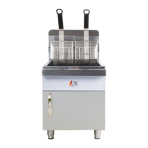
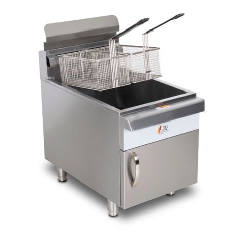
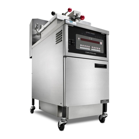
CPG 351FFOP40N User manual

www.cookingperformancegroup.com 1
Service Manual
351FFOP40N, 351FFOP50N, 351FFOP40L, 351FFOP50L
REVISED 06/2022
Open Pot Fryers
¾"
NOTICE
This manual is for a certied service technician and should not be used by those who are not properly trained.
This manual cannot cover all possible conditions that may occur and is not intended to be all encompassing.
You should read this manual in its entirety and the specic repair you wish to do prior to starting the repair.
This will allow you to determine if you have the correct tools, instruments, and skills to perform the procedure.

. www.cookingperformancegroup.com2
Service Manual
351FFOP40N, 351FFOP50N, 351FFOP40L, 351FFOP50L
Contents
Troubleshooting ..........................................3
Part Testing ..............................................4
Pre-Maintenance........................................4
Gas Combination Valve ..................................4
Gas Combination Valve Adjustments ......................4
Thermostat (200-400°F) .................................6
Thermostat Adjustment..................................6
High Limit Thermostat (450°F) ...........................6
Thermopile .............................................6
Burner Orices..........................................6
Thermostat Knob Post ...................................6
Part Replacement.........................................7
Gas Combination Valve ..................................7
Thermostat (200-400°F) .................................7
High Limit Thermostat (450°F) ...........................8
Thermopile .............................................8
Pilot Light ..............................................9
Burner Orices..........................................9
351ffop40l/N ....................................... 10
351ffop50l/N ....................................... 10
Wiring Diagram ........................................ 11
Parts Diagram .......................................... 12
351ffop40l/N ......................................... 12
351ffop50l/N ......................................... 13

User Manual
351CLCPG15NL, 351CLCPG24NL, 351CLCPG36NL,
351CLCPG48NL, 351CLCPG60NL, 351CLCPG72NL
www.cookingperformancegroup.com 3
Trouble Shooting
Service Manual
351FFOP40N, 351FFOP50N, 351FFOP40L, 351FFOP50L
PROBLEM POSSIBLE SOLUTION
Pilot light will not stay on
• Ensure gas is the correct type for the unit
• Ensure gas supply is turned ‘ON’
• Ensure gas supply is at the correct pressure
• Ensure pilot light orice is clean
• Ensure pilot light stays lit when knob is pressed
• Verify thermopile operation
• Check voltage strength of pilot light
• Check high limit thermostat
Burner will not turn on
• Ensure gas is the correct type for the unit
• Ensure gas supply is turned ‘ON’
• Ensure gas supply is at the correct pressure
• Ensure pilot light stays on during startup procedure
• Ensure combination valve knob is turned to ‘ON’
• Verify thermopile operation
• Check thermostat is turned ‘ON’
Burner will not turn o
• Check thermostat is turned ‘OFF’
• Verify thermostat operation
• Check thermostat adjustment
• Check gas combination valve is turned ‘OFF’
Oil leaking from fryer pot • Ensure drain valve is closed
• Ensure thermostat capillary wire plug is tight
• Ensure high limit thermostat capillary wire plug is tight
Oil not reaching temperature
• Check gas combination valve is turned ‘ON’
• Check that burners have a good ame when ‘ON’
• Check manifold pressure setting matches name plate on unit
• Check thermostat temperature dial setting
• Check thermostat adjustment is correct
Oil not staying at temperature
• Ensure thermostat probe is clean
• Check gas combination valve is tuned ‘ON’
• Check that burners have a good ame when ‘ON’
• Check manifold pressure setting matches name plate on unit
• Check thermostat temperature dial setting
• Check thermostat adjustment is correct
Burner ames are small or weak
• Check gas supply pressure is correct
• Check manifold pressure setting matches name plate on unit
• Check gas combination valve is turned ‘ON’
• Check burner openings, wire brush clean if needed
• Check orice opening for each burner
• Check gas combination solenoid operation
Burner ame will not light or
maintain ame
• Check gas combination valve is turned ‘ON’
• Check gas supply pressure is correct
• Check manifold pressure setting matches name plate on unit
• Check thermostat temperature dial setting
• Check thermostat adjustment is correct
• Check gas combination solenoid operation
Burners are producing a black soot • Ensure correct gas is supplied
• Ensure correct ventilation is set up

. www.cookingperformancegroup.com4
Part Testing
CAUTION: Components Can Be Hot
Follow these pre-maintenance steps before servicing
your Cooking Performance Group Floor Fryer
PRE-MAINTENANCE:
1. Turn thermostat to the “OFF”
position (Fig. 1)
2. Turn knob, on combination gas valve,
to the “OFF” position, align with
“RED” dot (Fig. 2)
3. Turn off gas supply to unit (Fig. 3)
(Supplied by others)
4. Allow unit to cool as needed
GAS COMBINATION VALVE:
• Thermopile voltage with pilot light on
= 250 - 750 millivolts DC with thermostat
in “OFF” position (Fig. 4)
• If too low, adjust pilot light ame strength,
see below
• Knob in “ON” position, Thermostat in “ON”
position, coil voltage should be higher than
120 millivolts
• If the coil voltage is below 120 millivolts DC,
replace combination valve
GAS COMBINATION VALVE
ADJUSTMENTS:
Adjusting Pilot Light Strength
1. Remove screw cap covering pilot adjustment
screw, located next to the pilot light gas hose,
with a at head screwdriver (Fig. 5)
2. With a small at head screwdriver, turn the
adjusting screw to increase or decrease pilot
light strength as needed
Counterclockwise = Increase
Clockwise = Decrease
3. Reinstall cover cap when correct strength has
been reached
Pilot light strength check
1. Pilot light should have a minimum
millivolt reading of 250, 500 or more is
recommended (Fig. 6)
FIG. 3
FIG. 5
FIG. 4
FIG. 6
FIG. 1 FIG. 2
Service Manual
351FFOP40N, 351FFOP50N, 351FFOP40L, 351FFOP50L

User Manual
351CLCPG15NL, 351CLCPG24NL, 351CLCPG36NL,
351CLCPG48NL, 351CLCPG60NL, 351CLCPG72NL
www.cookingperformancegroup.com 5
Manifold pressure check
1. With Thermostat in “OFF” position and gas
combination valve in the “OFF” position
2. Remove pressure tap plug from manifold with
7/16” wrench (Fig. 7)
3. Install tting for manometer, ensure there
are no gas leaks
4. With manometer ready, ignite the pilot ame and
turn knob on gas combination valve to the “ON”
position
5. Turn thermostat temperature knob ‘ON’ to ignite
burners, ensure oil is covering burner tubes inside
fryer pot
6. Manometer should read
4” of W. C. for natural gas and
10” of W. C. for propane
7. Use thread sealing compound or tape when re-
installing plug
8. Check connections for gas leaks
Adjust manifold pressure, if needed. Ensure
incoming gas pressure matches name plate on unit
1. Remove cover cap with at head screwdriver
(Fig. 8)
2. Use at head screwdriver to turn adjusting screw
Clockwise = Increase
Counterclockwise = Decrease
3. Reinstall cover cap when correct pressure has
been reached
FIG. 7 FIG. 8
Service Manual
351FFOP40N, 351FFOP50N, 351FFOP40L, 351FFOP50L

. www.cookingperformancegroup.com6
THERMOSTAT (200-400°F)
• Audible click can be heard when turned
‘ON’ / ‘OFF’
• If no click can be heard - Replace Thermostat
• Disconnect wires from thermostat, check continuity
of thermostat: OFF = No continuity / ON =
Continuity
• Replace if any checks fail
THERMOSTAT ADJUSTMENT
Thermostat is set at the factory and should maintain
temperatures within 10°F
Recalibrate if needed : if done more than
once, replace
1. Remove Thermostat dial from shaft (Fig. 31)
NOTE: Be careful not to rotate the dial as that will
change the temperature
2. Hold the dial shaft, “B” so it does not move
3. While holding dial shaft, “B”, turn calibration
screw, “A”
Clockwise = Decrease Temperature
Counterclockwise = Increase Temperature
4. Replace dial and allow unit to operate and
temperature to stabilize
5. Re-adjust if necessary
6. When done adjusting, seal calibration screw with
glyptol paint or similar product
7. Reinstall thermostat dial
HIGH LIMIT THERMOSTAT (450°F)
• Remove wires from high limit thermostat
• Continuity can be checked across wire connections
• If no continuity, replace high limit thermostat
• If high limit cools, continuity may be found, check
oil temperatures
• High limit thermostat should not ‘OPEN’ under oil
temperature of 425° F
THERMOPILE
• When heated by pilot light, thermopile should
support 250 millivolts to 750 millivot (500 millivolts
or higher is recommended)
• Replace if millivolts are less than 250, and/or pilot
ame has been increased in strength
BURNER ORIFICES
• Burner with poor ames, large yellow tipped ames
or missing sections of ames should be cleaned
• Good Flame = almost completely blue with a light
blue triangle at the bottom center
• Clean the burner with a wire brush to remove any
clogs that may have formed
• If clogs cannot be removed, replace the burner
Thermostat Knob Post
FIG. 9 FIG. 10
Decrease
Increase
¼ Turn changes
temperature
18°F
Calibration
Screw (A)
Dial
Shaft (B)
Service Manual
351FFOP40N, 351FFOP50N, 351FFOP40L, 351FFOP50L

User Manual
351CLCPG15NL, 351CLCPG24NL, 351CLCPG36NL,
351CLCPG48NL, 351CLCPG60NL, 351CLCPG72NL
www.cookingperformancegroup.com 7
GAS COMBINATION VALVE
1. Follow pre-maintenance steps on page 4
2. Remove wiring from combination
valve for thermostat and thermopile
connections (Fig. 11A)
3. Remove pilot light gas hose connection
(Fig. 11B)
4. Remove pipe unions from outlet and inlet side of
valve (Fig. 12A & B)
5. Remove inlet and outlet pipe sections from valve
6. Installation is reverse of removal with thread
sealant
7. Check for leaks with leak detection
solution or device
8. Verify correct manifold pressure during burner
operation, check name plate
THERMOSTAT (200-400°F)
1. Follow pre-maintenance steps on page 4
2. Pull thermostat control knob from front of
thermostat, replace control knob if necessary
3. Remove 2 Phillips screws from the front mounting
bracket (Fig. 13)
4. Remove wiring from thermostat, note locations to
move to new thermostat
(Fig. 15)
5. Pry apart holding tongs on the bracket inside the
fryer pot holding the sensing probe. (Fig. 16)
6. Remove holding nut for thermostat capillary wire
from front side of fryer pot with 18mm wrench (Fig.
14)
7. Remove thermostat capillary wire and sensing
probe from fryer pot
8. Installation is reverse of removal, ensure sensing
bulb is mounted in tongs before tightening holding
nut
9. Use thread sealant on holding nut for capillary wire
and ensure no leaks after install
FIG. 11
FIG. 13
FIG. 15
FIG. 12
FIG. 14
FIG. 16
A
A
B
B
Service Manual
351FFOP40N, 351FFOP50N, 351FFOP40L, 351FFOP50L

. www.cookingperformancegroup.com8
HIGH LIMIT THERMOSTAT (450°F)
1. Follow pre-maintenance steps on page 4
2. Remove 2 hex head screws from side of mounting
bracket, 8mm socket (Fig. 18)
3. Remove wiring from high limit thermostat, note
locations to move to new high limit thermostat
(Fig. 17)
4. Pry apart holding tongs on the bracket inside the
fryer pot holding the sensing probe. (Fig. 19)
5. Remove holding nut for high limit thermostat
capillary wire from underside
of fryer pot with 18mm wrench (Fig. 20)
6. Remove high limit thermostat capillary
wire and sensing probe from fryer pot
7. Installation is reverse of removal, ensure sensing
bulb is mounted in tongs before tightening
holding nut
8. Use thread sealant on holding nut for capillary wire
and ensure no leaks after install
THERMOPILE
1. Follow pre-maintenance steps on page 4
2. Remove wires from high limit thermostat that go
to thermopile (Fig. 17)
(White and Red color)
3. Remove two hex head screws that hold thermopile
bracket in place with an 8mm socket. (Fig. 23)
4. Remove compression nut from thermopile mount
with a 7mm wrench, do not lose compression nut
(Fig. 22)
5. Remove thermopile from mount by
pulling down
6. Slide on compression nut from old thermopile to
new thermopile
7. Ensure thermopile is fully seated in mounting
bracket before tightening compression nut
8. Installation is reverse of removal
FIG. 17 FIG. 18
FIG. 20
FIG. 22
FIG. 19
FIG. 21
FIG. 23
Service Manual
351FFOP40N, 351FFOP50N, 351FFOP40L, 351FFOP50L

User Manual
351CLCPG15NL, 351CLCPG24NL, 351CLCPG36NL,
351CLCPG48NL, 351CLCPG60NL, 351CLCPG72NL
www.cookingperformancegroup.com 9
PILOT LIGHT
1. Follow pre-maintenance steps on page 4
2. Remove two hex head screws that hold the pilot
light bracket in place (Fig. 24 )
3. Remove pilot light compression nut from the
bottom of the pilot light ame deector with a
13mm wrench (Fig. 26)
4. Transfer thermopile to new pilot light mounting
bracket
5. Installation is reverse of removal
6. Check all connections for gas leaks
BURNER ORIFICES
1. Follow pre-maintenance steps on page 4
2. Remove hex head screw from rear burner bracket
with an 8mm socket. (Fig. 27; shown from rear
of unit)
3. Remove 2 hex head screws with an 8mm socket
from either side of the drain valve (Fig. 28)
4. Remove union on gas piping. (Fig. 29)
5. Drop burner tubing down to gain access to orices
6. Remove orices as needed. (Fig. 30)
7. Installation is reverse of removal
8. Check all connections for gas leaks
FIG. 24
FIG. 26
FIG. 30
FIG. 25
FIG. 27
FIG. 29FIG. 28
Service Manual
351FFOP40N, 351FFOP50N, 351FFOP40L, 351FFOP50L

. www.cookingperformancegroup.com10
Orice Sizes
351FFOP40L/N
351FFOP50L/N
LIQUID PROPANE ORIFICE SIZING
ORIFICE SIZE ELEVATION (FEET)
61 Sea Level - 2,000
62 2,000 - 4,000
63 4,000 - 6,000
64 6,000 - 7,000
65 7,000 - 9,000
66 9,000 - 10,000
LIQUID PROPANE ORIFICE SIZING
ORIFICE SIZE ELEVATION (FEET)
68 Sea Level - 2,000
69 2,000 - 5,000
70 5,000 - 8,000
71 8,000 - 10,000
NATURAL GAS ORIFICE SIZING
ORIFICE SIZE ELEVATION (FEET)
52 Sea Level - 3,000
53 3,000 - 8,000
54 8,000 - 10,000
NATURAL GAS ORIFICE SIZING
ORIFICE SIZE ELEVATION (FEET)
53 Sea Level - 2,000
54 2,000 - 7,000
55 8,000 - 10,000
Service Manual
351FFOF40N, 351FFOP40L, 351FFOP50N, 351FFOP50L

www.cookingperformancegroup.com 11
Wiring Diagram
TP TP
TH/TP
Limit
R
E
D
W
H
T
T-stat TH
Service Manual
351FFOP40N, 351FFOP40L, 351FFOP50N, 351FFOP50L

. www.cookingperformancegroup.com12
Parts Diagram
351FFOP40L/N
ITEM# DESCRIPTION PART#
1Thermostat (200˚F - 400˚F) 351200728
2High Limit Thermostat (450˚F) 351200737
3Thermostat Knob 351103628
4Pilot Light tubing 351400070
5A Pilot Light, Propane 351201302019
5B Pilot Light, Natural 351201302028
6Thermopile 351700237
7A Combination Valve, Propane 351200500782
7B Combination Valve, Natural 351200500773
8A Burner Orice, Propane 3510150198L
8B Burner Orice, Natural 3510150198N
8
46
2
3
1
5
7
Service Manual
351FFOP40N, 351FFOP40L, 351FFOP50N, 351FFOP50L

www.cookingperformancegroup.com 13
Parts Diagram
351FFOP50L
ITEM# DESCRIPTION PART#
1Thermostat (200˚F - 400˚F) 351200728
2High Limit Thermostat (450˚F) 351200737
3Thermostat Knob 351103628
4Pilot Light Tubing 351400070
5A Pilot Light, Propane 351201302019
5B Pilot Light, Natural 351201302028
6Thermopile 351700237
7A Combination Valve, Propane 351200500782
7B Combination Valve, Natural 351200500773
8A Burner Orice, Propane 3511501991L
8A Burner Orice, Natural 3511501964N
7
8
5
6
2
3
1
4
Service Manual
351FFOP40N, 351FFOP40L, 351FFOP50N, 351FFOP50L
Other manuals for 351FFOP40N
1
This manual suits for next models
3
Table of contents
Other CPG Fryer manuals
