CPG CF15-NG User manual

1
Countertop Fryer
Installation and Operation Instructions
Model: CF15-NG, CF15-LPG, CF30-NG, CF30-LPG
IMPORTANT FOR FUTURE REFERENCE
Please complete this information and retain this manual for the life of the equipment. For
Warranty Service and/or parts, this information is required.
Model Number Serial Number Date Purchased
WARNING:For your safety, do not store or use gasoline or other flammable vapors or
liquids in the vicinity of this or any other appliances. Keep the area free and clear of
combustible materials. (See ANSI Z83. 14B, 1991).
WARNING
:
Improper installation, adjustment, alteration, service or maintenance can
cause property damage, injury, or death. Read the installation, operating and
maintenance instructions thoroughly before installing, or servicing this equipment.
WARNING
:
Instructions must be posted in a prominent location. All safety precautions
must be taken in the event the user smells gas. Safety information can be obtained from
your local gas supplier.
CAUTION: These models are designed, built, and sold for commercial use only. If these
models are positioned so the general public can use the equipment, make sure that
cautions, warnings, and operating instructions are clearly posted near each unit so that
anyone using the equipment will use it correctly and not injure themselves or harm the
equipment.
GAS PRESSURE
The appliance and it’s individual shutoff valve (to be supplied by user) must be disconnected from
the gas supply piping system during any pressure testing of that system at test pressures in excess
of ½ psi (3.45 kPa).
The appliance must be isolated from the gas supply piping system by closing it’s individual manual
shut-off valve during any pressure testing of the gas supply piping system at test pressures equal to
or less than ½ psi (3.45 kPa).
WARNING
:
A factory authorized agent should handle all maintenance and repair. Before
doing any maintenance or repair, contact your authorized service representative.

2
Congratulations on your purchase of Cooking Performance Group commercial cooking equipment.
Cooking Performance Group takes pride in the design and quality of our products. When used as
intended and with proper care and maintenance, you will experience years of reliable operation
from this equipment. To ensure best results, it is important that you read and follow the
instructions in this manual carefully.
TABLE OF CONTENTS:
ITEM
PAGE
ITEM PAGE
Safety precautions 3 Cleaning & Maintenance 7
General Installation Instructions 4 Troubleshooting 9
Specifications & Dimensions
4
Explosion View Drawing 10
Lighting Instructions 5 Spare Part List
Limited Warranty
11-12
13
Operating Instructions 6

3
LOCATION OF DATA PLATE
The data plate is located on the side panel.
IMMEDIATELY INSPECT FOR SHIPPING DAMAGE
All equipment should be examined for damage before and during unloading. The freight carrier
has assumed responsibility for its safe transit and delivery. If equipment is received damaged,
either apparent or concealed, a claim must be made with the delivering carrier.
A) Apparent damage or loss must be noted on the freight bill at the time of delivery. It must then
be signed by the carrier representative (Driver). If this is not done, the carrier may refuse the claim.
The carrier can supply the necessary forms.
B) If concealed damage is not apparent until after equipment is uncrated, a request for inspection
must be made to the carrier within 15 days. The carrier should arrange an inspection. Be certain to
hold all contents and packaging material.
Installation and service should be performed by a qualified installer who thoroughly reads,
understands and follows these instructions.
If you have questions concerning the installation, operation, maintenance or service of this
product, visit Cooking Performance Group’s website at www.CookingPerformanceGroup.com.
SAFETY PRECAUTIONS
DANGER
:
This symbol warns of imminent hazard which will result in serious injury or
death.
WARNING: This symbol refers to a potential hazard or unsafe practice, which could result
in serious injury or death.
CAUTION: This symbol refers to a potential hazard or unsafe practice, which could result
in minor or moderate injury or product or property damage.
NOTICE: This symbol refers to information that needs special attention or must be fully
understood even though not dangerous.
NOTICE: This product is intended for commercial use only. Not for household use.
NOTICE: Local codes regarding installation vary greatly from one area to another. The
National Fire Protection Association, Inc., states in its NFPA96 latest edition that local
codes are “Authority Having Jurisdiction” when it comes to requirement for installation
of equipment. Therefore, installation should comply with all local codes.

4
GENERAL INSTALLATION INSTRUCTIONS
Ensure gas supply and gas type, as shown on unit nameplate, agree.
Unit installation must conform with the National Fuel Gas Code, ANSI Z223.1/NFPA 54, the
National Gas Installation Code, CSA-B149.1, or the Propane Installation Code, CSA-B149.2 as
applicable and in accordance with local codes.
Screw legs into the permanently fastened nuts on the four corners of the unit and tighten by hand.
Level the unit by turning the adjustment screw at the bottom of each leg. Do not slide unit with
legs mounted, lift if necessary to move unit.
Pipe threading compound must be resistant to the action of liquefied petroleum gases.
Caution: DO NOT use an open flame to check for leaks. Check all gas piping for leaks with a soap
and water solution before operating unit.
THESE UNITS ARE SUITABLE FOR INSTALLATION ON NON-COMBUSTIBLE SURFACES ONLY.
Combustible clearances:
6" sides (152 mm) 6" rear (152 mm) 4" floor (102 mm)
Noncombustible clearances:
0" sides (0 mm) 0" rear (0 mm) 4" floor (102 mm)
Do not obstruct the flow of combustion and ventilation air under the unit by the legs or behind
the unit by the flue.
Adequate clearance for air openings into the combustion chamber is required. Do not place
objects between the bottom of the unit and the counter top.
There must be adequate clearance for removal of the front panel. All major parts except the
burners are removable thru the front if the gas line is disconnected.
SPECIFICATIONS AND DIMENSIONS
MODEL WIDTH
IN. (MM)
DEPTH
IN. (MM)
HEIGHT
IN. (MM)
# OF
BURNERS
BTU/PER
NAT/LP
TOTAL
BTU/Hr
Work Pressure
In.w.c
CF15-NG
11(260)
29(735)
26.8(680)
2
13,250
26,500
4
CF15-LPG 11(260) 29(735) 26.8(680) 2 13,250 26,500 10
CF30-NG 17(430) 29(735) 26.8(680) 4 13,250 53,000 4
CF30-LPG
17(430)
29(735)
26.8(680)
4
13,250
53,000
10
Note: regulator – 75mm/3.25 inch depth. Dimensions above do not include regulator.

5
LIGHTIING INSTRUCTIONS
Fryers are furnished with a Gas Control Safety Valve. Please follow the instructions below.
Before Lighting Pilot and Burners
Fill the fat tank about 3/4" below the full line with proper frying compound before lighting pilot. The
reason for filling the tank 3/4" below the full line is that the frying compound will expand during the
preheating process.
If the frying compound expands above the full line, the frying compound may overflow out of the
tank during the cooking process. The reason for adding fry compound in fry tank before lighting
the pilot or burners is that the unit will be damaged if this is not done.
Operating Instructions:
Step 1. Ensure the Gas Control Valve dial is at the “OFF” position.
Step 2. Ensure the thermostat dial is at the “OFF” position.
Step 3. Turn the Gas Control Valve dial to “Pilot” position and hold. Press the pilot ignition button.
In order to drain any air within the gas pipe system, for the first use, please hold the Valve dial at
the “Pilot” position for 5-7 minutes until lit.
If Gas Fryer pilot light will not ignite, please hold an ignition source (a match) at the pilot. When
the flame is established, remove the Ignition source.

6
Step 4. Turn the Gas Control Valve dial to the “ON“ position and using the thermostat dial,
set the desired temperature. You can monitor the flame status through this panel
Instructions for Draining Oil:
A drain extension pipe has been attached to the inside of the main door.
Screw the drain extension pipe into the main drain valve. Once secured, use the blue handle; turn
the valve on to release the oil.
OPERATING INSTRUCTIONS
All burners are lit from constantly burning pilots. Turning the thermostat to the desired
temperature is all that is required to put the unit in service.
Do not permit fans to blow directly at the unit. Wherever possible, avoid open windows next to
the unit's sides or back. Avoid wall type fans which create air cross-currents within a room. It is
also necessary that sufficient air should be allowed to enter the room to compensate for the
amount of air removed by any ventilating system. Otherwise, a subnormal atmospheric pressure
will occur, which will effect operation and cause undesirable working conditions.
A properly designed and installed hood will act as the heart of the ventilating system for the room
or area in which the unit is installed and will leave the unit independent of changing draft
conditions.
All valves and thermostats must be checked periodically. Consult the authorized service
representative in your area.

7
CLEANING
Initial Cleaning
Always clean equipment thoroughly before first use. Clean the protective oil from the bright parts
and interior of tank with a solution of washing soda or other grease dissolving material.
Daily Cleaning
1. Always turn unit off and allow it to cool completely before cleaning.
2. Never clean unit by immersing it in water.
3. The frequency of cleaning should depend on the load conditions. Set a definite cleaning
schedule corresponding to how hard the kettle is used. Cleaning should be done at a least once a
week.
4. Strain the frying compound into a clean container. Make sure there is no compound left in tank.
(If the tank is left empty for more than 2 minutes, shut the pilot off. If this is not done, the tank
may be damaged.)
5. Add water to the "MAX" line.
6. Add any food grade cleaner and follow cleaner instructions.
7. Turn the thermostat to 250°F. Let the heating unit bring the solution to a boil.
8. Boil long enough to loosen or dissolve all varnish or carbon deposits. This should take
approximately 30 minutes.
9. Turn the unit off. Make sure pilot is turned off at this time.
10. If necessary, clean the thermostat probes using a long-handled fiber or plastic brush and mild
soap solution.
11. Rinse with clean water to remove all cleaning mixture.
12. Rinse the inside of the tank with 2 cups of vinegar.
13. Rinse with clean water until the vinegar odor is gone. The fry tank must be thoroughly rinsed
since even a trace of cleaner left inside the tank will contaminate the fry compound.
14. Dry thoroughly.
15. Cover the tank if compound will not be added until a future date.
16. Clean all exterior surfaces of unit on a regular basis with a damp cloth. Thin films of oil
subjected to frying temperatures quickly form into a gummy consistency. In order to avoid these
gum formations, clean the surfaces on a regular basis.
17. To remove discolorations or oil film, a non-abrasive cleaner may be used.
CAUTION: Clean the regulator at least once a month. Make sure the vent opening is open
and not blocked in any way. Failure to do so will cause variations in pressure. Your unit
will not function as well and it could shorten the life of the product.
MAINTENANCE
OVER NIGHT SHUTDOWN
Turn the temperature control knob to the off position. Or turn the Off/Pilot/On valve control to
Pilot if you wish not to change the temperature setting. (The pilot flame alone will keep the frying
compound temperature to 130-145°F when not under any load. This will shorten preheat time
when turned back on.)
EXTENDED SHUTDOWN (4 DAYS OR LONGER)
1. Turn the temperature control knob to the off position.
2. Turn the Off/Pilot/On valve control knob to the off position.
3. Turn the manual control valve under the unit to the off position.

8
4. Turn the supply valve to the off position (not supplied by Cooking Performance Group).
5. The entire flue duct opening on the top rear of unit must always be left uncovered.
Filling Fry Tank
(CAUTION: NEVER LIGHTPILOT OR TURN BURNERS ON WITH EMPTY TANK)
1. Fill the fry tank approximately 3/4" below the full line. The fry compound will expand as it
is heated. Heat the fry compound to 375° F for 20 minutes then check the level. Add or
decrease amount of fry compound so it lines up with the full line.
2. When using solid frying compound, put enough compound in fry tank so at least half or more of
the tank has compound in it. Then set the temperature to 200 ° F on dial and allow the compound
to liquefy. Add to adjust compound level.
3. Use a quality frying compound.
4. Filter the frying compound frequently, at least once a day.
5. Skim out food particles frequently with a strainer/skimmer.
6. Add at least 15% (of fry tank capacity) of fresh frying compound daily (more if possible) without
overloading tank. If 15% of frying compound is not used daily, remove some of the compound for
other use (griddle frying, etc.) to permit adding 15% of fresh compound daily.
7. Do not overload the fry baskets. This will result in longer recovery time, longer cook time, and
compound absorption into the product.
8. Prepare the food properly.
9. Keep salt out of the frying compound. Do not salt foods with the basket above the kettle.
10. Ensure a good thermostat operation by checking frying compound temperature with a reliable
frying thermometer. Temperature of compound should be comparable to thermostat setting.
11. Keep the fry tank and thermo-probes clean.
Thermostat Calibration
The fryer control is factory calibrated. If cooking results indicate unit is not maintaining correct
temperatures, consult an authorized service representative.
SERVICE
/
REPAIR
NOTE: THISAPPLIANCE MUST ONLY BE SERVICED BYANAUTHORIZEDAGENT.
NOTE: Parts protected by the manufacturer or his agent are not to be adjusted by the installer,
unless the installer is an authorized service agent.
If you have any questions or problems, contact your nearest Service Representative.

9
TROUBLE SHOOTING GUIDE
PROBLEM
POSSIBLE CAUSE
Frying Temperature Too High/Overheating
(Check Thermostat)
Frying Temperature Too Low/Underheating
(Check Thermostat)
Over loading Fryer
Improper Draining of Food After Frying
High Moisture Content in Food Being Fried
Inadequate
Frying Compound Turnover
Improper Preparation of Food
Contamination of Fryer
Compound (Due to salt or other foreign
material)
Excessive & Premature Foaming
★
★
★
★
Greasy Food / Excessive Frying Compound
Absorption
★★★★★★
Objectionable Odor or Flavor of Frying
Compound
★
★
★
Objectionable Flavor of Fried Food
★
★
★
Excessive Smoking of Frying Compound ★★★★
Excessive Darkening of Frying Compound ★★★★
Frying Compound Won’t Hold Heat ★★★★
Food Crust Color Not Brown ★★★★
Rapid Breakdown of Frying Compound ★★★★
LC series limit control
10
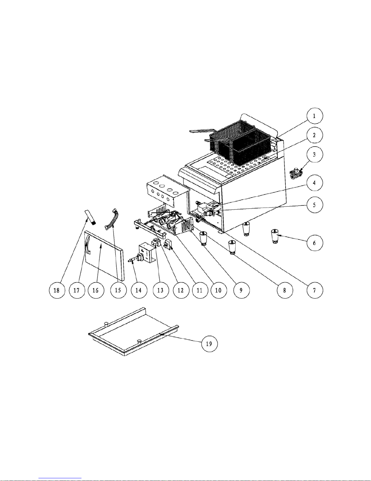
EXPLOSION VIEW DRAWING
MODEL: CF30-NG / CF30-LPG

11
Spare Parts List
NO. DESCRIPTION MODEL CODE QTY
1 Basket CF15-NG / CF15-LPG
CF30-NG / CF30-LPG 01.02.1005190 1
2
2 Filter Panel CF15-NG / CF15-LPG
CF30-NG / CF30-LPG
01.05.1026472
01.05.1026210 1
3CF15-NG / CF15-LPG
CF30-NG / CF30-LPG 01.22.1069501 1
4Pilot pipe
(With Sleeve)
CF15-NG / CF15-LPG 01.02.1005201
01.18.1067454
1
CF30-NG / CF30-LPG 01.02.1005197
01.18.1067454
5 Gas Safety control valve
CF15-NG / CF30-NG 06.05.1470654
1
CF15-LPG / CF30-LPG 06.05.1470674
6 Adjustable Foot CF15-NG / CF15-LPG
CF30-NG / CF30-LPG 01.02.1005373 4
7 Valve, Oil Drain CF15-NG / CF15-LPG
CF30-NG / CF30-LPG 01.20.1068677 1
8 Burner CF15-NG / CF15-LPG
CF30-NG / CF30-LPG 06.05.1470489 2
4
9 Flame Device System
CF15-NG / CF30-NG 01.21.1069001
1
CF15-LPG / CF30-LPG 01.21.1069003
10 Thermopile CF15-NG / CF15-LPG
CF30-NG / CF30-LPG 03.11.1250027 1
11 Gas Thermostat CF15-NG / CF15-LPG
CF30-NG / CF30-LPG 03.05.1220047 1
12
Orifice 51# NG CF15-NG
CF30-NG 01.20.1068651 2
4
Orifice 58# LPG CF15-LPG
CF30-LPG 01.20.1068658 2
4
13 LC Series Limit Control CF15-NG / CF15-LPG
CF30-NG / CF30-LPG 03.99.1290101 1
14 Piezo Igniter CF15-NG / CF15-LPG
CF30-NG / CF30-LPG 03.99.1290152 1
Regulator 6”-NAT or
10"-LP, 3/4" -PT

12
15 Bellows CF15-NG / CF15-LPG
CF30-NG / CF30-LPG 01.02.1005117 1
16 Door CF15-NG / CF15-LPG 06.05.1470658 1
CF30-NG / CF30-LPG 06.05.1470653
17 Door Handle CF15-NG / CF15-LPG
CF30-NG / CF30-LPG 01.02.1005070 1
18 Oil Drain Pipe CF15-NG / CF15-LPG
CF30-NG / CF30-LPG 01.02.1005195 1
19 Cover
(Optional Accessories)
CF15-NG / CF15-LPG 06.05.1470668 1
CF30-NG / CF30-LPG 06.05.1470669
Cooking Performance Group
Lancaster, Pennsylvania
Website: www.CookingPerformanceGroup.com

13
Limited Warranty
Cooking Performance Group Cooking Equipment Models:
Griddles: G15, G24, G36, G48, G15T, G24T, G36T, G48T
Charbroilers: CBL15, CBL24, CBL36, CBL48, CBR15, CBR24, CBR36, CBR48
Hot Plates: HP212, HP424, HP636
Fryers: CF15, CF30
All new Cooking Performance Group Griddles, Charbroilers, Hot Plates, and Fryers used for
commercial purpose are warranted against defects in materials and workmanship under normal use
and maintenance. The Warranty runs for one year from the date of original installaon and is for
the benefit of the original purchaser only. All other warranes, expressed or implied, statutory or
otherwise, including without limitaon any implied warranty of merchantability for fitness for
purposes are excluded. The seller shall in no event be liable for direct, indirect or consequenal
damages in connecon with Cooking Performance Group commercial products.
Exclusions
The following condions are not covered by warranty:
•Equipment damage or equipment failure occurs because of accident, carelessness, lack of
proper set-up, supervision when required, or if the equipment is installed or operated in any
manner contrary to the installaon and operang instrucons.
•Equipment damage or equipment failure due to improper installaon, improper ulity
connecon or supply, and problems due to venlaon.
•Equipment that has not been used appropriately, or has been subject to misuse, neglect,
abuse, accident, alteraon, negligence, damage during transit, delivery or installaon, fire,
flood, or act of God.
•Equipment that has the model number or serial number removed or altered.
•Equipment that has been changed, altered, or modified or repaired by other than an
Authorized Service Agency. Cooking Performance Group shall not be held liable for any
damages to any person or property which may result from the use of the equipment
thereaer.
This warranty does not apply to, and Cooking Performance Group is not responsible for any
warranty claims on products sold or used outside of the conguous United States.
This equipment is intended for commercial use only. Warranty is void if equipment is installed in
other than commercial applicaons.
This manual suits for next models
3
Table of contents
Other CPG Fryer manuals


