CPG 351S24(L/N) User manual

USER MANUAL
Gas Restaurant Ranges
MODELS: 351S24(L/N), 351S36(L/N), 351S36G12(L/N),
351S60(L/N), 351S60G24(L/N), 351S36G24(L/N), 351S60GS24(L/N)
4003027

2 www.CookingPerformanceGroup.com
USER MANUAL
IMMEDIATELY INSPECT FOR SHIPPING DAMAGE
All equipment should be examined for damage before and during unloading. The freight carrier has assumed
responsibility for its safe transit and delivery. If equipment is received damaged, either apparent or concealed, a
claim must be made with the delivering carrier.
A) Apparent damage or loss must be noted on the freight bill at the time of delivery. It must then be
signed by the carrier representative (Driver). If this is not done, the carrier may refuse the claim. The
carrier can supply the necessary forms.
B) If concealed damage is not apparent until after equipment is uncrated, a request for inspection must
be made to the carrier within 5 days. The carrier should arrange an inspection. Be certain to hold all
contents and packaging material.
Installation and service should be performed by a qualied installer who thoroughly reads, understands and
follows these instructions. If you have questions concerning the installation, operation, maintenance or service of
this product, visit Cooking Performance Group’s website at www.CookingPerformanceGroup.com.
SAFETY PRECAUTIONS
DANGER: This symbol warns of imminent hazard which will result in serious injury or death. WARNING: This
symbol refers to a potential hazard or unsafe practice, which could result in serious injury or death.
CAUTION: This symbol refers to a potential hazard or unsafe practice, which could result in minor or moderate
injury or product or property damage.
NOTICE: This symbol refers to information that needs special attention or must be fully understood even
though not dangerous. NOTICE: This product is intended for commercial use only. Not for household use.
NOTICE: Local codes regarding installation vary greatly from one area to another. The National Fire Protection
Association, Inc., states in its NFPA96 latest edition that local codes are “Authority Having Jurisdiction” when it
comes to requirement for installation of equipment. Therefore, installation should comply with all local codes.
FOR YOUR SAFETY: Do not store or use gasoline or other ammable vapors and liquids in the vicinity of this
or any other appliance.
WARNING: Improper installation, adjustment, alteration, service or maintenance can cause property damage,
injury or death. Read the installation, operating and maintenance instructions thoroughly before installing or
servicing this equipment. This manual must be retained for future reference. Keep adequate clearance for air
openings into the combustion chamber.
Congratulations on your purchase of Cooking Performance Group commercial cooking equipment. Cooking
Performance Group takes pride in the design and quality of our products. When used as intended and with proper
care and maintenance, you will experience years of reliable operation from this equipment. To ensure best results, it is
important that you read and follow the instructions in this manual carefully.
LOCATION OF DATA PLATE The data plate is located on the side panel.

www.CookingPerformanceGroup.com 3
USER MANUAL
FEATURES AND SPECIFICATIONS
30,000 BTU Open Top Burners with Standing Pilot Ignition
•Cast iron lift-o grates
•Deep pull-out crumb tray with welded corners
•(2) 20,000 BTU U-shaped burners for griddle models
•30,000 BTU Oven with tube style burner
•250-550 degrees Fahrenheit temperature range
•2 oven racks with 4 rack positions per oven compartment
•26 7/8”W x 25 7/8”D x 13 7/8”H
•6” adjustable stainless steel legs
CONTENTS
Specications: 2-6
Installation Instructions: 7-8
Operation: 9-10
Troubleshooting: 11
Parts Diagrams: 12-22
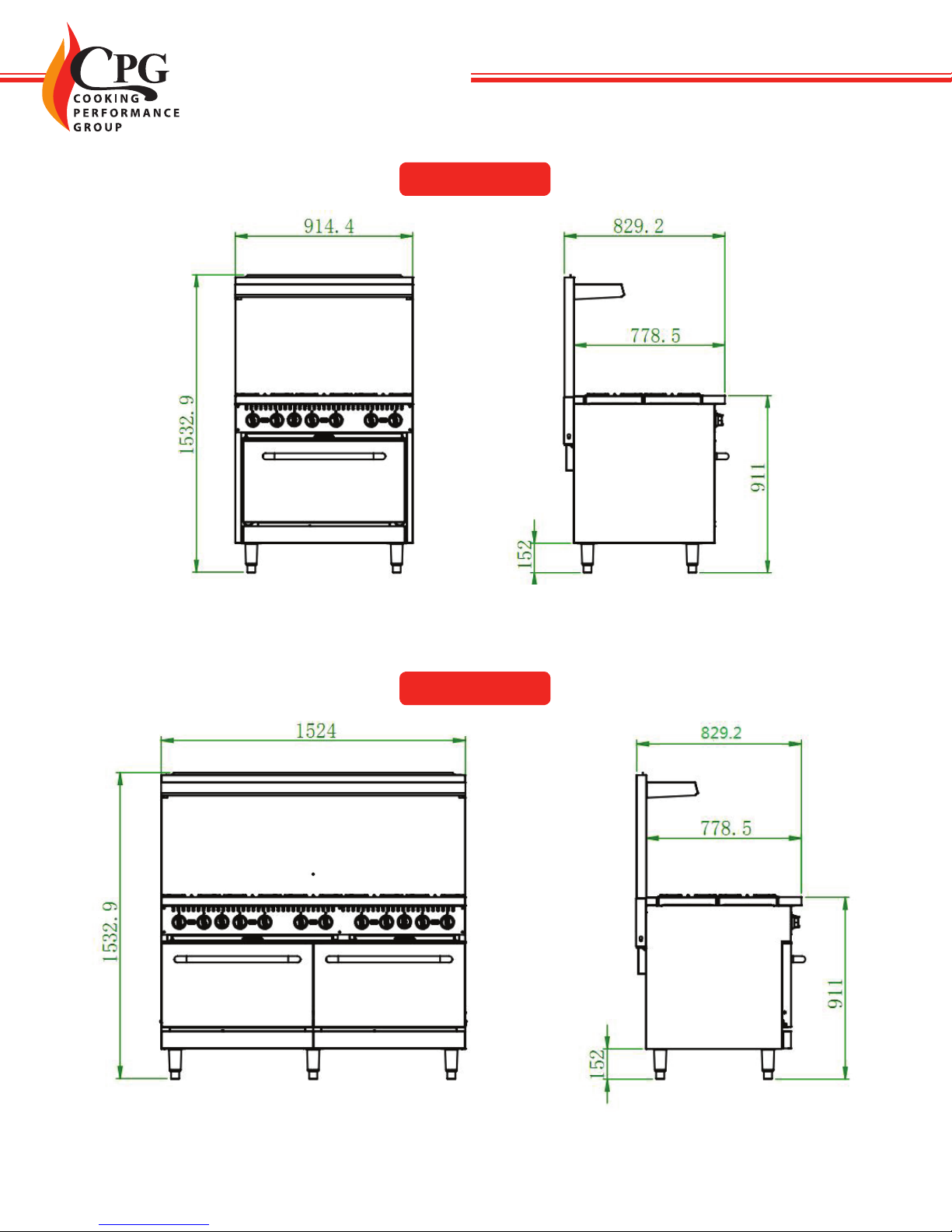
MODEL DIMENSION (IN) OVEN TEMPERATURE (F) POWER (BTU) LP/NG LP PRESSURE GAS TYPE NG PRESSURE GAS TYPE
351S24(L/N) 24” × 32 5/8” × 60 3/8” 250-550 150,000 10” 4”
351S36(L/N) 36” x × 32 5/8” × 60 3/8” 250-550 210,000 10” 4”
351S60(L/N) 60” x × 32 5/8” × 60 3/8” 250-550 360,000 10” 4”
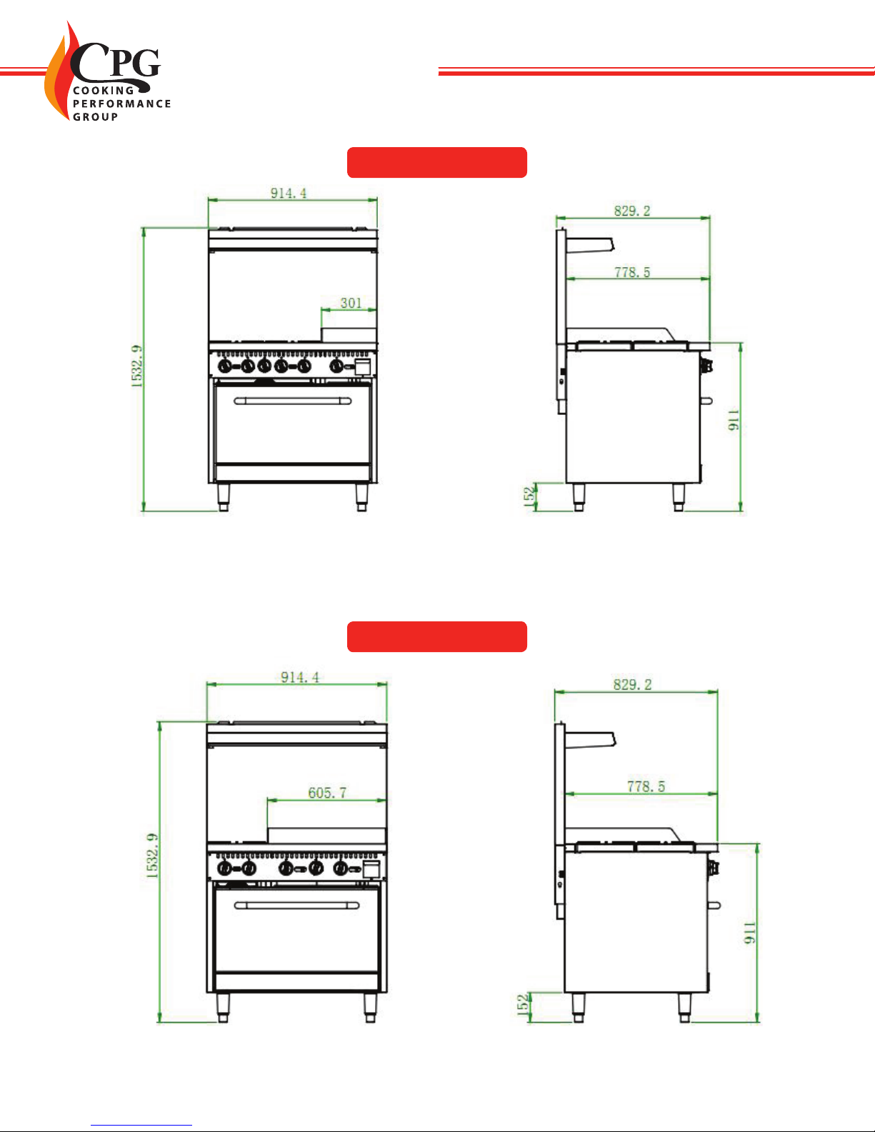
351S36G12(L/N) 36” x × 32 5/8” × 60 3/8” 250-550 170,000 10” 4”
351S36G24(L/N) 36” x × 32 5/8” × 60 3/8” 250-550 130,000 10” 4”
351S60G24(L/N) 60” x × 32 5/8” × 60 3/8” 250-550 280,000 10” 4”
351S60GS24(L/N) 60” x × 32 5/8” × 60 3/8” 250-550 276,000 10” 4”
351S24(L/N)
4 www.CookingPerformanceGroup.com
USER MANUAL
351S36(L/N)
351S60(L/N)
www.CookingPerformanceGroup.com 5
USER MANUAL
351S36G12(L/N)
351S36G24(L/N)

6 www.CookingPerformanceGroup.com
USER MANUAL
351S60G24(L/N)
351S60GS24(L/N)

www.CookingPerformanceGroup.com 7
USER MANUAL
INSTALLATION INSTRUCTIONS
THESE UNITS ARE SUITABLE FOR INSTALLATION ON NON-COMBUSTIBLE
SURFACES ONLY. DO NOT INSTALL IT NEAR ANY COMBUSTIBLE SURFACES.
GAS CONNECTION
NOTE: This device ships from the factory congured for areas whose altitude is lower than 6500 feet.
Contact at www.CookingPerformanceGroup.com.
1. Ensure gas supply and gas type, as shown on unit nameplate agree. Unit installation must conform with the
National Fuel Gas Code, ANSI Z223.1/NFPA 54, the National Gas Installation Code, CSA-B149.1, or the Propane
Installation Code, CSA-B149.2 as applicable and in accordance with local codes.
2. A manual gas shut-o valve must be installed in the gas supply line ahead of the appliance and gas pressure
regulator for safety and ease in servicing.
3. The gas pressure regulator supplied must be installed on the appliance prior to connecting the equipment to
the gas line. Failure to install a regulator could be potentially hazardous and will void the appliance warranty.
4. Pipe threading compound must be resistant to the action of liqueed petroleum gases.
CAUTION: DO NOT use an open ame to check for leaks. Check all gas piping for leaks with a soap and water
solution before operating unit.
Cumbustible Clearance Requirements: 6”sides, 6” back
Make sure that the oor where you plan to locate the oven is capable of supporting its weight along with any
accessories. Adequate clearance should be provided for proper operation and servicing.
Level the oven once you’ve uncrated it in your facility. You can compensate for an uneven oor with the
leveling feet.
Proper ventilation is crucial to safe and optimum performance. Ensure that the oven is installed underneath a
ventilation hood according to all applicable local and national codes.

8 www.CookingPerformanceGroup.com
USER MANUAL
FINAL PREPARATION
Your new range has a plastic coating to help protect the nish from scratches during shipping. This protective
plastic lm should be peeled o prior to starting the range.
CAST IRON TOP GRATES
Seasoning the grates before their rst use and after each cleaning will help prevent them from rusting.
•Remove the grates and wash them thoroughly with mild soap and warm water, then dry them with a
clean cloth.
•After drying, immediately season the grates with vegetable oil. DO NOT SEASON THE GRATES WHILE
ON THE RANGE TOP!
•After seasoning, reinstall the grates and turn all the burners to “low” for approximately 20 minutes before
using pots or pans.
OVEN
•Wash and dry the interior as well as oven racks with soap and water before rst use.
•It is normal for an unpleasant smell to be noticeable the rst time the oven is used. This is caused by the
burn-o of any grease or solvents left over from the manufacturing process. Before cooking food in the
oven for the rst time, turn the oven on and set it to its maximum temperature until the smell dissipates.
GRIDDLE (if applicable)
CAUTION: This griddle plate is steel, but the surface is relatively soft and can be scored or dented by the
careless use of a spatula or scraper. Be careful not to dent, scratch, or gouge the plate surface. Do not try to knock
o loose food that may be on the spatula by tapping the corner edge of the spatula on the griddle surface.
Remove all factory applied protective material by washing with hot water, mild detergent or soap solution.
Because the metal surface of the griddle is porous, a new griddle surface must be seasoned before its rst use
to prevent sticking and prolong its life. To season, heat the griddle top section at a low burner setting. Pour
one ounce of cooking oil per square foot of surface and spread it around to create a thin lm with a cloth. Wipe
o any excess oil. Heat the griddle slowly for 15 to 20 minutes, and then wipe away any excess oil. Repeat this
procedure 2 to 3 times until the griddle has a slick surface.
NOTE: The griddle surface may discolor during this process. This will not aect its performance and is not a
defect.
You should not have to re-season the griddle surface if you use it properly. If it gets overheated or products begin
to stick, you may need to repeat the seasoning process. You will also need to re-season it if you clean it with soap
and water.

www.CookingPerformanceGroup.com 9
USER MANUAL
OPERATING INSTRUCTIONS
HOT TOP AND GRIDDLE TOP BURNERS:
1. Light the pilot adjacent to each burner
2. Push and turn the burner valve 90 degrees counterclockwise, and the burner will ignite.
CAUTION: Should burner ignition fail within 4 seconds, turn the burner valve o and repeat steps 1 through 2.
If ignition continues to fail, consult your factory authorized service agency.
OVEN:
1. Open the kick plate under the oven door.
2. Press down the temperature control knob and rotate it counterclockwise to align the “ ” mark with the
notch on the bezel. Hold the knob down.
3. Ignite the pilot ame with a lighter via the ignition hole.
4. After the pilot ame is ignited, continue holding the knob for more than 20 seconds to heat up the
thermocouple. If the pilot light goes out after this, repeat steps 2-4 until it stays lit.
5. Keep rotating the temperature control knob counterclockwise to ignite the main burner of the oven. Select
appropriate temperature according to food requirement
To turn o the burner: Rotate the knob clockwise to align the pointer on the knob with the notch on the bezel.
OFF
MAX
MIN

10 www.CookingPerformanceGroup.com
USER MANUAL
CLEANING & MAINTENANCE
Regular cleaning and maintenance will maintain the appearance and performance of your range for years to
come. Follow these tips to keep your range operating at its best.
BURNERS AND GRATES
• Wipe any spills as they occur
• Remove grids and trays daily to wash, rinse, and dry them
• Use a wire brush to clean any clogged burner ports
• For baked on material, a wire brush may be used
• Lightly coat the grates with vegetable oil after cleaning to help prevent rust from forming
GRIDDLE (if applicable)
Keeping the griddle surface free of carbonized grease for maximum heat transfer, even cooking, and satisfactory
food taste and appearance.
•AFTER EACH USE: Use a grill scraper or spatula to wipe o any excess food particles leftover from the
cooking process
•DAILY: clean griddle surface using a grill brick and grill pad. Clean and empty the grease pan.
•WEEKLY: Clean surface thoroughly. A mild detergent or degreaser may be used but be sure to make
sure it is thoroughly removed. Re-season the grill surface to prevent rusting and maintain its nonstick
properties.
OVEN
• Oven racks and oven guides may be removed and cleaned with soap and water.
• The rest of the oven interior may be cleaned with a suitable oven cleaning product.

www.CookingPerformanceGroup.com 11
USER MANUAL
All these examples are provided for your reference. If any failure occurs, please stop using, and consult a qualied
service technician. All maintenance should be done after the power supply and gas supply are shut down.
TROUBLESHOOTING
SYMPTOMS CAUSES SOLUTIONS
The pilot ame cannot be ignited 1. The gas pressure is too low.
2. The nozzle is blocked.
3. Connection of the thermocouple is loose.
4. The thermocouple is defective.
5. The gas control valve is malfunctioning.
1. Adjust the release valve to get a proper pressure.
2. Unblock the nozzle.
3. Tighten the thermocouple.
4. Replace the thermocouple
5. Replace the gas control valve.
The pilot ame is on but the main
burner cannot be ignited
1. The gas pressure is too low.
2. The main burner nozzle is blocked.
3. The gas control valve is defective.
1. Adjust the relieve valve to get a proper pressure.
2. Unblock the nozzle.
3. Replace the gas control valve.
The oven backres 1. The diameter of nozzle does not match with
the gas supply.
2. The damper is too large.
3. The gas pressure is too low.
4. The ow of the connected pipe is insucient.
1. Adjust the nozzle diameter.
2. Adjust the damper.
3. Adjust the relieve valve.
4. Increase the permitted ow.
The ame is red and accompanied
by black smoke
1. The diameter of the nozzle does not match the
gas supply.
2. The damper is too small.
3. The gas supply has run out.
4. The gas regulator reduces the gas ow in gas
peak demand.
1. Adjust the nozzle diameter.
2. Adjust the damper.
3. Replace the gas.
4. Decrease the gas ow and increase it after the
peak demand of the gas.
12 www.CookingPerformanceGroup.com
USER MANUAL
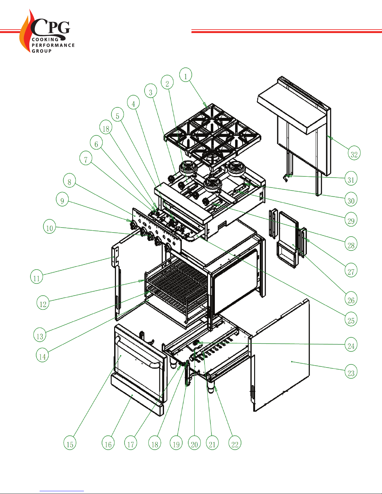
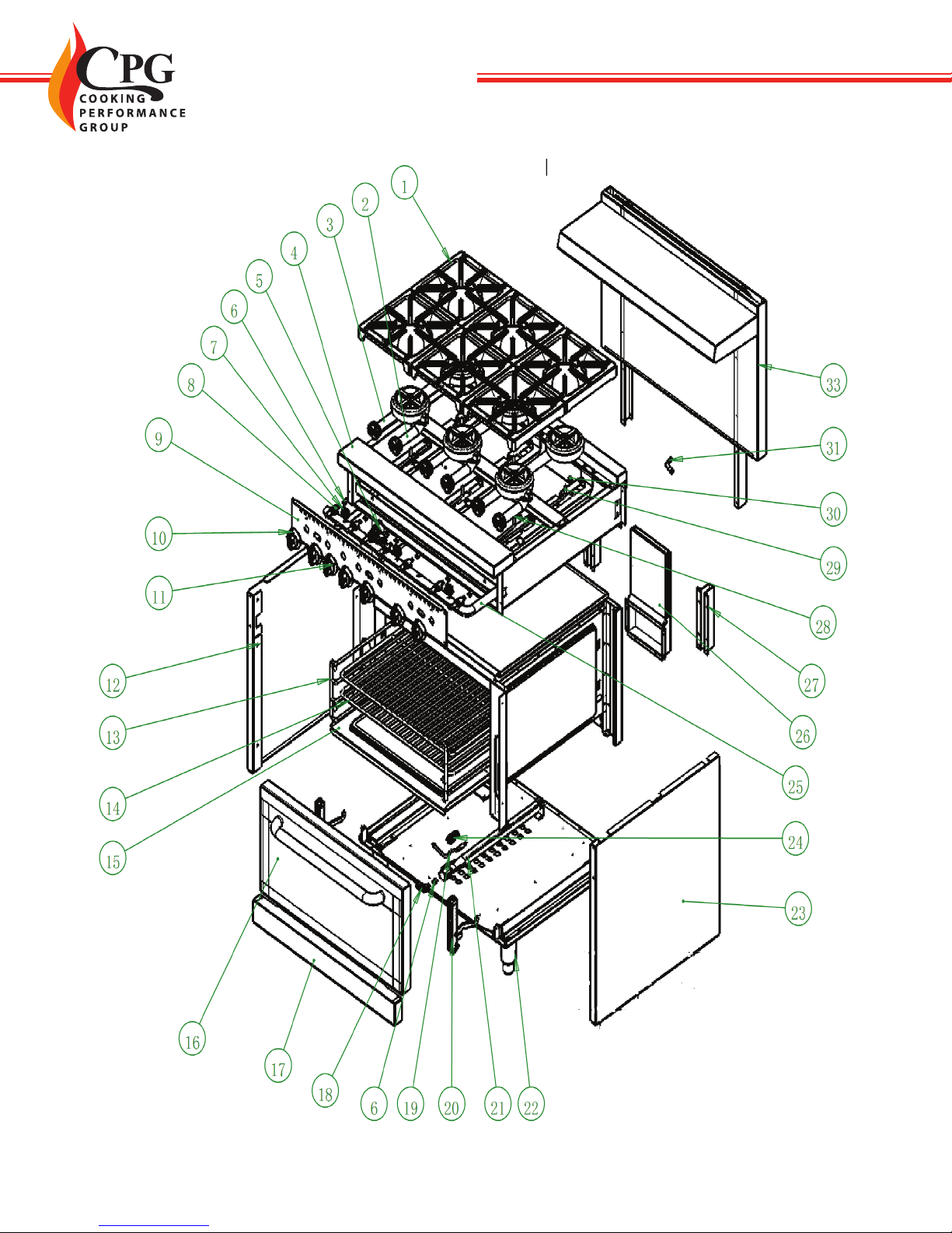
PARTS DIAGRAM 351S24L/N
# PART NUMBER OUR ITEM NUMBER DESCRIPTION QTY
1302250132 351302250132 BURNER GRATE 4
220128051028 351128051028 BURNER ASSEMBLY (SHORT) 2
320128051027 351128051027 BURNER ASSEMBLY (LONG) 2
420128058002 351128058002 FRAME ASSEMBLY 1
5302220064 351302220064 GAS OVEN VALVE 1
6302220027 351302220027 PILOT VALVE 2
7302050051 351302050051 GAS STOVE VALVE 4
820228058005 351228058005 FRONT CONTROL PANEL 1
920228051057+301110390 351202230111 STOVE KNOB 4
10 20228051061+301110389 351301130111 OVEN KNOB 1
11 20228058020 351228058020 SIDE PANEL(Left) 1
12 302110504 351302110504 RACK HOLDER 2
13 302110557 351302110557 RACK (CHAMBER) 2
14 20428058001 351428058001 BASEBOARD (CHAMBER) 1
15 20128058024 351128058024 DOOR ASSEMBLY 1
16 20228058021 351228058021 LOWER FRONT BEAM SLAB 1
17 302140137 351302140137 NOZZLE ELBOW 1
18 302150132 351302150132 NOZZLE 5
20 302170045 351302170045 THERMOCOUPLE 1
21 302130384 351302130384 OVEN TUBE BURNER 1
22 302090149 351302090149 ADJUSTABLE LEG 4
23 20228058019 351228058019 SIDE PANEL (Right) 1
24 302130365(NG)/302130366(LPG) 351302130365 OVEN PILOT 1
25 302180496 351302180496 GAS INLET PIPE ASSEMBLY 1
26 20128051007 351128051007 INNER FLUE ASSEMBLY 1
27 20228051044 351228051044 SLIDE RAIL (REAR BAFFLE) 2
28 20228046015 351228046015 GAS PIPE (PILOT)(SHORT BURNER) 2
29 20228046016 351228046016 GAS PIPE (PILOT)(LONG BURNER) 2
30 302130019 351302130019 STOVE PILOT 4
31 302060231 351302060231 PIPE FIXER 1
32 20128058007 351128058007 BACK PANEL ASSEMBLY 1
www.CookingPerformanceGroup.com 13
USER MANUAL

14 www.CookingPerformanceGroup.com
USER MANUAL
PARTS DIAGRAM 351S36L/N
# PART NUMBER OUR ITEM NUMBER DESCRIPTION QTY
1302250132 351302250132 BURNER GRATE 6
220128051028 351128051028 BURNER ASSEMBLY (SHORT) 3
320128051027 351128051027 BURNER ASSEMBLY (LONG) 3
420128051002 351128051002 FRAME ASSEMBLY 1
5302220064 351302220064 GAS OVEN VALVE 1
6302150132 351302150132 NOZZLE 7
7302220027 351302220027 PILOT VALVE 3
8302050051 351302050051 GAS STOVE VALVE 6
920228051005 351228051005 FRONT CONTROL PANEL 1
10 20228051057+301110390 351202230111 STOVE KNOB 6
11 20228051061+301110389 351301130111 OVEN KNOB 1
12 20228051032 351228051032 SIDE PANEL (LEFT) 1
13 302110504 351302110504 RACK HOLDER 2
14 302110503 351302110503 RACK (CHAMBER) 2
15 20428051001 351428051001 BASEBOARD (CHAMBER) 1
16 20128051030 351128051030 DOOR ASSEMBLY 1
17 20228051031 351228051031 LOWER FRONT BEAM SLAB 1
18 302140137 351302140137 NOZZLE ELBOW 1
19 302170045 351302170045 THERMOCOUPLE 1
21 302130384 351302130384 OVEN TUBE BURNER 1
22 302090149 351302090149 ADJUSTABLE LEG 4
23 20228051030 351228051030 SIDE PANEL (HOUSING)(RIGHT) 1
24 "302130365(NG)/302130366(LPG)" 351302130365 OVEN PILOT 1
25 302180441 351302180441 GAS INLET PIPE ASSEMBLY 1
26 20128051007 351128051007 INNER FLUE ASSEMBLY 1
27 20228051044 351228051044 SLIDE RAIL (REAR BAFFLE) 2
28 20228046015 351228046015 GAS PIPE (PILOT)(SHORT BURNER) 3
29 20228046016 351228046016 GAS PIPE (PILOT)(LONG BURNER) 3
30 302130019 351302130019 STOVE PILOT 6
31 302060231 351302060231 PIPE FIXER 1
33 20128051006 351128051006 BACK PANEL ASSEMBLY 1
www.CookingPerformanceGroup.com 15
USER MANUAL
16 www.CookingPerformanceGroup.com
USER MANUAL
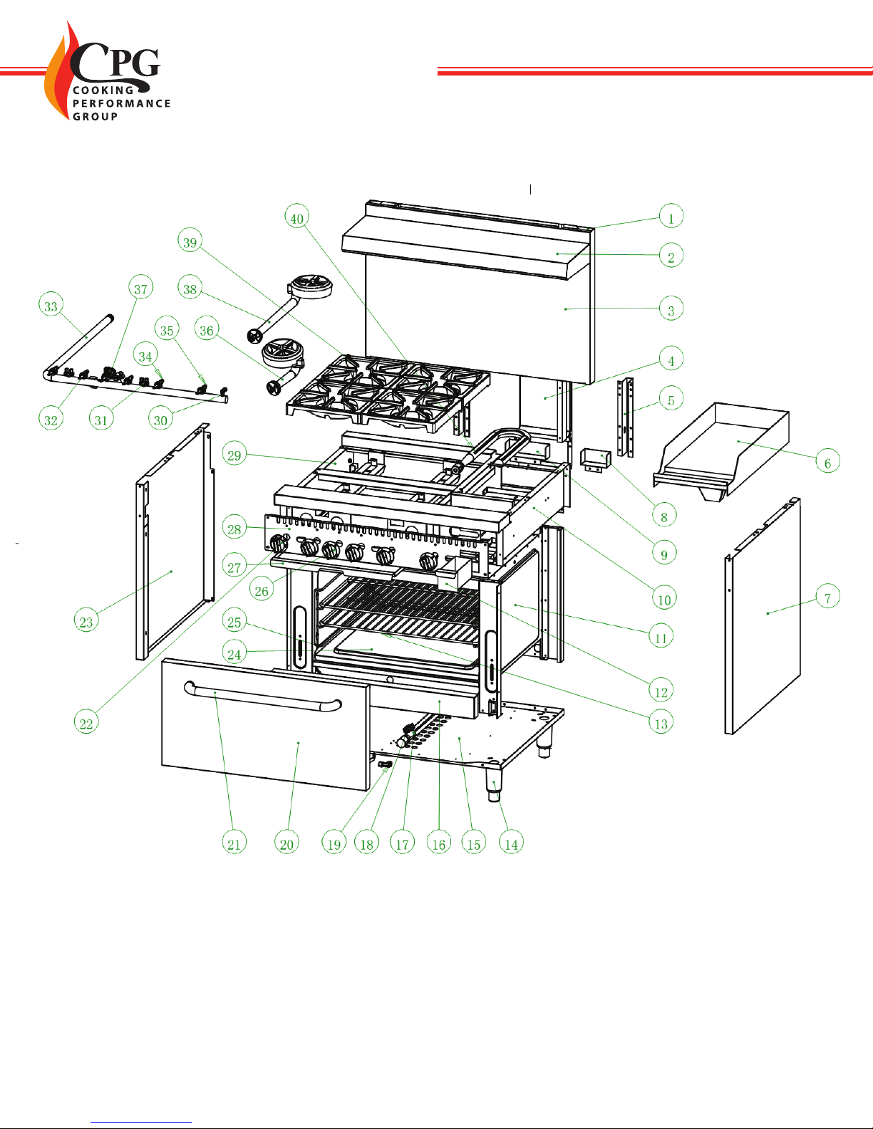
PARTS DIAGRAM 351S36G12L/N
# PART NUMBER OUR ITEM NUMBER DESCRIPTION QTY
120228051039 351228051039 REAR PANEL (BACK) 1
220228051041 351228051041 DECORATION COVER 1
320228051038 351228051038 FRONT PANEL (BACK) 1
420128051007 351128051007 INNER FLUE ASSEMBLY 1
520228051044 351228051044 SLIDE RAIL (REAR BAFFLE) 2
620128076006 351128076006 GRIDDLE PLATE ASSEMBLY 1
720228077009 351228077009 RIGHT SIDE PANEL 1
820228077011 351228077011 FLUE SHEET (GRIDDLE) 1
920228076011 351228076011 FLUE SHEET (GRIDDLE) 1
10 20128076005 351128076005 FRAME ASSEMBLY (GRIDDLE) 1
11 20128051004 351128051004 CHAMBER ASSEMBLY (OVEN) 1
12 20128078006 351128078006 OIL PAN ASSEMBLY 1
13 302110503 351302110503 CHAMBER RACK (OVEN) 2
14 302090149 351302090149 6 INCH ADJUSTABLE LEG 4
15 20228051029 351228051029 SHEEL BOTTOM PLATE 1
16 20228051031 351228051031 LOWER FRONT SLAB 1
17 302130384 351302130384 TUBE BURNER 1
18 302130365 351302130365 PILOT (NG) 1
18 302130366 351302130366 PILOT (LPG) 1
19 302150132 351302150132 OVEN NOZZLE 1
20 20228051100 351228051100 DOOR EXTERIOR PLATE( WITHOUT LOGO HOLE) 1
21 302070144 351302070144 DOOR HANDLE 1
22 20228051057+301110390 351202230111 STOVE&GRIDDLE KNOB 5
23 20228077010 351228077010 LEFT SIDE PANEL 1
24 20428051001 351428051001 OVEN CHAMBER BOTTOM PLATE 1
25 302110504 351302110504 RACK HOLDER 2
26 20228051061+301110389 351301130111 OVEN KNOB 1
27 20228058007 351228058007 CRUMB TRAY 1
28 20228076003 351228076003 FRONT CONTROL PANEL 1
29 20128076002 351128076002 FRAME ASSEMBLY (GAS RANGE) 1
30 302220028 351302220028 NG/LPG REGULATING VALVE AP7-1 1
31 302220027 351302220027 NG/LPG REGULATING VALVE AP6-1 2
32 302050051 351302050051 PB100 VALVE 5
33 302180623 351302180623 GAS INLET PIPE ASSEMBLY 1
34 302150132 351302150132 STOVE NOZZLE 4
35 302150132 351302150132 GRIDDLE NOZZLE 1
36 20128051028 351128051028 SHORT BURNER ASSEMBLY 2
37 302220064 351302220064 OVEN VALVE 1
38 20128051027 351128051027 LONG BURNER ASSEMBLY 2
39 302250132 351302250132 GRATE 4
40 302130387 351302130387 GRIDDLE BURNER 1
www.CookingPerformanceGroup.com 17
USER MANUAL
18 www.CookingPerformanceGroup.com
USER MANUAL
PARTS DIAGRAM 351S36G24L/N
# PART NUMBER OUR ITEM NUMBER DESCRIPTION QTY
120228051039 351228051039 REAR PANEL (BACK) 1
220228051038 351228051038 FRONT PANEL (BACK) 1
320228051044 351228051044 SLIDE RAIL (REAR BAFFLE) 2
420128051007 351128051007 INNER FLUE ASSEMBLY 1
520228051040 351228051040 BRACE (BACK PANEL) 2
620128077005 351128077005 FRAME ASSEMBLY (GRIDDLE) 1
720128078007 351128078007 GRIDDLE PLATE ASSEMBLY 1
820228077009 351228077009 RIGHT SIDE PANEL 1
9302130387 351302130387 GRIDDLE BURNER 2
10 20228077016 351228077016 CRUMB TRAY 1
11 20128051004 351128051004 OVEN CHAMBER ASSEMBLY 1
12 20128078008 351128078008 DRIP PAN ASSEMBLY 1
13 302090149 351302090149 ADJUSTABLE LEG 4
14 20428051001 351428051001 OVEN CHAMBER BOTTOM PLATE 1
15 302150132 351302150132 NOZZLE 1
16 20228051031 351228051031 LOWER FRONT BEAM 1
17 20228051033 351228051033 DOOR EXTERIOR PLATE(WITHOUT LOGO HOLE) 1
18 302070144 351302070144 DOOR HANDLE 1
19 302130365 351302130365 PILOT (NG) 1
19 302130366 351302130366 PILOT (LPG) 1
20 302130384 351302130384 OVEN BURNER 1
21 302110504 351302110504 RACK HOLDER 2
22 302110503 351302110503 RACK (OVEN CHAMBER) 2
23 20228051061+301110389 351301130111 OVEN KNOB 1
24 20228077007 351228077007 FRONT CONTROL PANEL 1
25 20228077006 351228077006 FRONT COUNTERTOP 1
26 20228051057+301110390 351202230111 STOVE KNOB 4
27 20228077005 351228077005 CRUMB TRAY 1
28 20228077010 351228077010 LEFT SIDE PANEL 1
29 20128051028 351128051028 SHORT BURNER ASSEMBLY 1
30 302220064 351302220064 GAS VALVE 1
31 302150132 351302150132 GRIDDLE NOZZLE 2
32 302220027 351302220027 NG/LPG REGULATING VALVE 1
33 302050051 351302050051 PB100 VALVE 4
34 302150132 351302150132 STOVE NOZZLE 2
35 302180622 351302180622 GAS INLET PIPE ASSEMBLY 1
36 302220028 351302220028 NG/LPG REGULATING VALVE 2
37 20128051027 351128051027 LONG BURNER ASSEMBLY 1
38 302250132 351302250132 GRATE 2
39 20228077012 351228077012 FLUE SHEET (GRIDDLE) 1
40 20228077011 351228077011 FLUE SHEET (GRIDDLE) 1

www.CookingPerformanceGroup.com 19
USER MANUAL

20 www.CookingPerformanceGroup.com
USER MANUAL
PARTS DIAGRAM 351S60L/N
# PART NUMBER OUR ITEM NUMBER DESCRIPTION QTY
1302250132 351302250132 BURNER GRATE 10
220128051028 351128051028 BURNER ASSEMBLY (SHORT) 5
320128051027 351128051027 BURNER ASSEMBLY (LONG) 5
420128059002 351128059002 FRAME ASSEMBLY 1
5302220064 351302220064 GAS VALVE 2
6302220027 351302220027 PILOT VALVE 5
7302050051 351302050051 GAS VALVE 10
820228059007 351228059007 FRONT CONTROL PANEL 1
920228051057+301110390 351202230111 STOVE KNOB 10
10 20228051061+301110389 351301130111 OVEN KNOB 2
11 20228058020 351228058020 SIDE PANEL (Left) 1
12 302110504 351302110504 RACK HOLDER 4
13 302110503 351302110503 RACK (CHAMBER) 4
14 20428051001 351428051001 BASEBOARD (CHAMBER) 2
15 20128059010 351128059010 DOOR ASSEMBLY 2
16 20228059011 351228059011 LOWER FRONT BEAM SLAB 2
17 302140137 351302140137 NOZZLE ELBOW 2
18 302150132 351302150132 NOZZLE 12
19 302170045 351302170045 THERMOCOUPLE 2
21 302130384 351302130384 BURNER 2
22 302090149 351302090149 ADJUSTABLE LEG 6
23 20228058019 351228058019 SIDE PANEL(Right) 1
24 "302130365(NG)/302130366(LPG)" 351302130365 OVEN PILOT 2
25 302180497 351302180497 GAS INLET PIPE ASSEMBLY 1
26 20128051007 351128051007 INNER FLUE ASSEMBLY 2
27 20228051044 351228051044 SLIDE RAIL (REAR BAFFLE) 2
28 20228046015 351228046015 GAS PIPE (PILOT)(SHORT BURNER) 5
29 20228046016 351228046016 GAS PIPE (PILOT)(LONG BURNER) 5
30 302130019 351302130019 STOVE PILOT 10
31 302060231 351302060231 PIPE FIXER 1
32 20128059006 351128059006 BACK PANEL ASSEMBLY 1
Other manuals for 351S24(L/N)
1
This manual suits for next models
6
Table of contents
Other CPG Range manuals

CPG
CPG 351WOKR13L User manual

CPG
CPG 351IDCPG19A User manual

CPG
CPG 351CPGSPR18L User manual
 User manual")
CPG
CPG 351S24(L/N) User manual

CPG
CPG HP212 Installation instructions

CPG
CPG 351RCPG12NL User manual

CPG
CPG 351S24 Series User manual

CPG
CPG 351RCPG12NL User manual

CPG
CPG 351CPGSPR18 User manual

CPG
CPG 351SRCPG12NL User manual


