CPO Science DataCollector User manual


Copyright © 2004 CPO Science
6/04
DataCollector designed by: Dr. Thomas C. Hsu
Thomas S. Narro
David Zucker
in conjunction with: PRI
Darren Garnier

Table of Contents
Introduction . . . . . . . . . . . . . . . . . . . . . . . . . . . . . . . . . . . . . . . . . . . . . . . . . . . . . . . . 1
Overview . . . . . . . . . . . . . . . . . . . . . . . . . . . . . . . . . . . . . . . . . . . . . . . . . . . . . . . . . . . . . . 1
Kit Contents . . . . . . . . . . . . . . . . . . . . . . . . . . . . . . . . . . . . . . . . . . . . . . . . . . . . . . . . 5
Warnings and Precautions . . . . . . . . . . . . . . . . . . . . . . . . . . . . . . . . . . . . . . . . . . . . 6
Getting Started . . . . . . . . . . . . . . . . . . . . . . . . . . . . . . . . . . . . . . . . . . . . . . . . . . . . . 7
Features of the DataCollector . . . . . . . . . . . . . . . . . . . . . . . . . . . . . . . . . . . . . . . . . . . . . 7
Connecting the Zire Handheld . . . . . . . . . . . . . . . . . . . . . . . . . . . . . . . . . . . . . . . . . . . . . 7
Powering the DataCollector . . . . . . . . . . . . . . . . . . . . . . . . . . . . . . . . . . . . . . . . . . . . . . . 8
Connecting CPO Science Photogates . . . . . . . . . . . . . . . . . . . . . . . . . . . . . . . . . . . . . . . . 9
Connecting Other Probes & Adapters . . . . . . . . . . . . . . . . . . . . . . . . . . . . . . . . . . . . . . . 9
Setting up a Computer for use with the DataCollector . . . . . . . . . . . . . . . . . . . . . . . . . 10
Using the DataCollector . . . . . . . . . . . . . . . . . . . . . . . . . . . . . . . . . . . . . . . . . . . . . 11
Using the Zire Handheld . . . . . . . . . . . . . . . . . . . . . . . . . . . . . . . . . . . . . . . . . . . . . . . . . 11
Starting the DataCollector Application . . . . . . . . . . . . . . . . . . . . . . . . . . . . . . . . . . . . . . 11
Setting Up a New Experiment . . . . . . . . . . . . . . . . . . . . . . . . . . . . . . . . . . . . . . . . . . . . . 13
Navigating within the DataCollector Application . . . . . . . . . . . . . . . . . . . . . . . . . . . . . . 18
Application Menus . . . . . . . . . . . . . . . . . . . . . . . . . . . . . . . . . . . . . . . . . . . . . . . . . . . . . . 24
Downloading Data to a Computer . . . . . . . . . . . . . . . . . . . . . . . . . . . . . . . . . . . . 26
Mac OS 9.x and Mac OS X . . . . . . . . . . . . . . . . . . . . . . . . . . . . . . . . . . . . . . . . . . . . . . . 26
Windows . . . . . . . . . . . . . . . . . . . . . . . . . . . . . . . . . . . . . . . . . . . . . . . . . . . . . . . . . . . . . 26
Technical Information . . . . . . . . . . . . . . . . . . . . . . . . . . . . . . . . . . . . . . . . . . . . . . . 28
Analog Sensor Pinout . . . . . . . . . . . . . . . . . . . . . . . . . . . . . . . . . . . . . . . . . . . . . . . . . . . . 28
Digital Sensor Pinout . . . . . . . . . . . . . . . . . . . . . . . . . . . . . . . . . . . . . . . . . . . . . . . . . . . . 29
Accessory Information . . . . . . . . . . . . . . . . . . . . . . . . . . . . . . . . . . . . . . . . . . . . . . . . . . . 30
Software Updates and Website Information . . . . . . . . . . . . . . . . . . . . . . . . . . . . . . . . . 30
Glossary . . . . . . . . . . . . . . . . . . . . . . . . . . . . . . . . . . . . . . . . . . . . . . . . . . . . . . . . . . 31


1
DATACOLLECTOR HANDHELD USER’SGUIDE
Chapter 1: Introduction
The CPO Science DataCollector is a device used to view and record data from
various sensors, including analog sensors from Fourier Systems and Vernier, as
well as photogates from CPO Science.
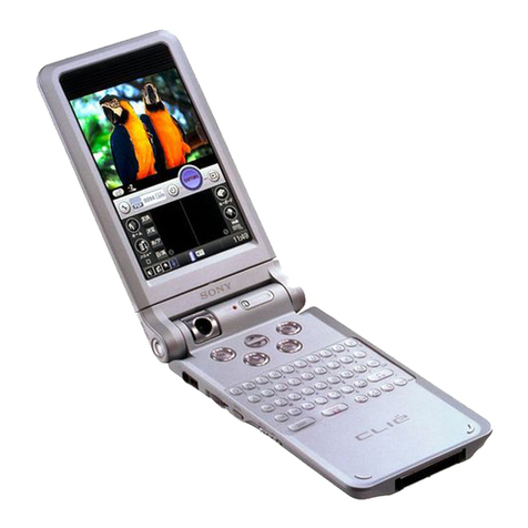
The DataCollector consists of a palmOne Zire™1handheld computer, and a “sled”
(referred to in this manual as “the hardware”) into which the handheld fits. Sensors
plug in to the hardware. See Figure 1 on page 2.
Once data has been collected, it can be analyzed in graph or table form on the
handheld computer, or transferred to a PC (via the Palm HotSync Utility and the
DataCollector Conduit included with your kit) for further analysis. See Figure 2 on
page 3.
Overview
Several components are involved in collecting and analyzing data with the CPO
Science DataCollector. They can be grouped according to two primary activities:
collecting data on the DataCollector and transferring data to and from the com-
puter.
Collecting Data
Using software running on the Zire handheld, data are recorded in tabular form.
During an experiment you can:
• start and stop data collection
• view live data
• view a live graph of the data
• view the experiment name and details
1. Zire is a trademark of palmOne, Inc.

2
Figure 1 shows the components used to collect data. They are:
• the DataCollector hardware
• the Zire handheld computer
• the CPO Science AC adapter
• analog sensors (a temperature sensor is shown)
• digital sensors (CPO Science photogates are shown)
See Table 2 on page 5 for a list of kit configurations.
Figure 1: Data Collection Components

3
DATACOLLECTOR HANDHELD USER’SGUIDE
Transferring and Analyzing Data
Figure 2 shows the components used to transfer and analyze data. They are:
• the Zire handheld computer
• the USB synchronization cable
• a Mac or Windows-based PC
• the HotSync Manager software
• the CPO Science DataCollector conduit software
After completing an experiment, the data can be transferred to a personal computer
for further analysis and manipulation. Each experiment from the Zire handheld is
saved on the PC as a comma separated value (CSV) file, readable by Microsoft
Excel, Mathworks Matlab, and many other programs.
Figure 2: Synchronization Components

4
Table 1 lists the software components involved in the transfer and analysis process.
Table 1: Software Components
Software Purpose Runs on... Source
DataCollector
App
Records data from
sensors and presents
graphs and tables
Zire
Handheld
DataCollector
Resource CD-ROM
or Support Website
HotSync
Manager
Performs HotSync oper-
ation between Zire
handheld and desktop
computer through USB
cable
Desktop
Computer
Zire Desktop
Software CD-ROM
DataCollector
Conduit
Transfers experimental
data from Zire handheld
to desktop computer as
part of a HotSync oper-
ation
Desktop
Computer,
in conjunc-
tion with
HotSync
Manager
DataCollector
Resource CD-ROM
or Support Website
Data Analysis
Software (such
as Microsoft
Excel or
Matlab)
Further analyze experi-
mental data using more
sophisticated graphical
or statistical methods
Desktop
Computer
Independent Soft-
ware Vendor (not
supplied with
DataCollector)

5
DATACOLLECTOR HANDHELD USER’SGUIDE
Chapter 2: Kit Contents
There are three different configurations of the DataCollector available. These are
summarized in Table 2 below.
Table 2: DataCollector Kits
DataCollector
Solo
DataCollector
Standard Kit
DataCollector
Starter Kit
Part #792-1500
Includes:
• 1 AC adapter
• 1 User's Guide
• 1 DataCollector
Software CD-ROM
Part #792-1503
Includes:
• 1 Hard carrying case
• 1 DataCollector Unit
• 1 AC adapter
• 1 User's Guide
• 1 Software CD-ROM
• 1 Zire handheld
• 1 Zire accessory pack
(Palm AC adapter,
software CD-ROM,
HotSync cable, etc.)
Part #792-1505
Includes:
• 1 Hard carrying case
• 1 DataCollector Unit
• 1 AC adapter
• 1 User's Guide
• 1 Software CD-ROM
• 1 Zire handheld
• 1 Zire accessory pack
(Palm AC adapter,
software CD-ROM,
HotSync cable, etc.)
• 2 CPO Science
Photogates
• 2 Telephone Cords
• 1 Voltage Probe

6
Chapter 3: Warnings and Precautions
Please make note of the following warnings and precautions. Failure to follow
these guidelines can result in damage to your DataCollector and possibly bodily
harm.
IMPORTANT: The AC adapter that comes with the Zire handheld
will not work with the DataCollector. Use only the 9V DC adapter
with the DataCollector that has the CPO Science name/logo on it.
IMPORTANT: Do not over-tighten the thumbscrew on the
photogates. Over-tightening can flex the body of the photogate
enough that the light emitter and receiver twist out of alignment,
causing the photogate to malfunction.
WARNING: Do not plug any lines from the telephone system in to
the DataCollector’s Analog or Digital ports. Telephone rings (also
present with modems) generate large voltages that can damage or
destroy the DataCollector.
WARNING: Computer data cables have the same (RJ-11) connec-
tors and look like the telephone cords used with photogates, but
are wired differently inside. Using a data cable will ruin the
photogates.
WARNING: When using the DataCollector, be sure not to exceed
the specifications on the voltage, current or other sensor(s) being
used. This can damage the sensor or cause serious injuries.

7
DATACOLLECTOR HANDHELD USER’SGUIDE
Chapter 4: Getting Started
Use the following diagrams and information to familiarize yourself with the CPO
Science DataCollector.
Features of the DataCollector
Figure 3 shows the components of the DataCollector hardware.
Figure 3: DataCollector Parts and Features
Connecting the Zire Handheld
To replace the handheld in the hardware, slide it on to the alignment pin and USB
connector, and then gently press the Zire handheld down until it snaps in place.
Avoid pressing any of the buttons.
To remove the Zire handheld from the DataCollector, gently pull back on the
spring clip until the handheld pops up. Then, gently slide it off the alignment pin
and USB connector.

8
Powering the DataCollector
Use only the provided 9V DC, 500 mA CPO Science adapter with the DataCollec-
tor. After connecting the adapter to the power jack on the DataCollector, slide the
power switch down. The indicator should light up red.
The Zire handheld’s battery will charge when connected to a DataCollector that is
powered - the indicator must be lit for the handheld to charge.
Zire Battery Life
If you purchased a DataCollector kit with a Zire handheld, the power adapter for
the Zire handheld was included. If you purchased your Zire handheld on your own,
be sure to keep the adapter that came with it. This adapter is labelled “Palm”.
If you don’t use the Zire handheld (with or without the DataCollector hardware)
for several weeks, the battery may become run down. If this happens, and the Zire
handheld will not turn on, remove it from the DataCollector hardware and plug it
in to the Palm adapter for several hours.
Depending on how long the Zire handheld’s battery was dead, you may need to re-
install the DataCollector software. Follow the directions on the CD-ROM that
came with the DataCollector, or visit http://support.cpo.com for more information.
Figure 4: DataCollector Port Identification

9
DATACOLLECTOR HANDHELD USER’SGUIDE
Connecting CPO Science Photogates
Connect CPO Science Photogates to either or both of the digital ports (shown in
Figure 4) with the telephone cords. These are the same cords and photogates used
with the CPO Science Timer.
Connecting Other Probes & Adapters
Fourier Probeware
Fourier Systems sensors can be used with the CPO Science DataCollector using
the Fourier Sensor Adapter (CPO Science Part #392-1511).
Connect the British Telecom end of the cable to either of the analog ports on the
DataCollector and the 8 pin mini-DIN end of the cable to a Fourier sensor.
Figure 5: Fourier Sensor Adapter
Vernier Probeware
Most Vernier probes with right-handed British Telecom connectors (Vernier part
numbers that end in -BTA) are supported. Plug these probes in to the analog ports
of the DataCollector, shown in Figure 4.
Pasco Probeware
Currently, most Pasco probeware is not supported. Check the CPO Science
DataCollector website for updates and adapter information.

10
Other Photogates
To use Fourier, Vernier, or Pasco photogates with the CPO Science DataCollector,
use the adapter to be released late 2004 (CPO Science Part #392-1513). No adapter
is necessary to use CPO Science Photogates with the DataCollector.
Setting up a Computer for use with the DataCollector
CPO Science provides software that enables you to download experimental data
from the Palm Zire handheld to your personal computer. This software, called the
DataCollector Conduit, is included with each kit on the DataCollector Resource
CD-ROM.
Currently, the conduit is supported on PC's running the Microsoft Windows oper-
ating system (Windows 98, Windows NT, Windows 2000 or Windows XP) and
computers running Mac OS 9.1 and above.
The DataCollector Conduit relies on the Palm HotSync Manager, and can only be
installed after the HotSync Manager software is set up. For help with HotSync
Manager installation, refer to the documentation that came with your Zire hand-
held or Palm's technical support website: http://www.palmone.com/us/support/
IMPORTANT: The HotSync Manager Software must be
installed before you install the DataCollector Conduit.
Windows 98/NT/2000/XP Installation
Once you have installed the HotSync Manager software, insert the CPO Science
DataCollector Resource CD-ROM and follow the instructions that appear on your
screen to install the conduit. If the instructions do not automatically appear,
double-click on the My Computer icon on your desktop, then on the CPO Science
DataCollector CD-ROM icon, and then on the Setup Information.html icon.
Mac Installation
After installing the HotSync Manager and Palm Desktop software on your com-
puter, insert the CPO Science Resource CD-ROM. Double-click on the CD-ROM
icon on your desktop when it appears, and then open the document called
Setup Information.html. Follow the instructions on your screen to install the
conduit.

11
DATACOLLECTOR HANDHELD USER’SGUIDE
Chapter 5: Using the DataCollector
Using the Zire Handheld
A good way to familiarize yourself with the Zire interface is through the manual
included on the CD-ROM that came with your handheld. Specifically, Chapter 2,
titled “Exploring Your Handheld,” covers basic operations such as starting applica-
tions, tapping on buttons and menu items, and entering text.
IMPORTANT: This guide assumes you are familiar with the
basics of using the Zire handheld.
Starting the DataCollector Application
After powering on the DataCollector hardware as described in the section
“Powering the DataCollector” on page 8, start the DataCollector application on the
handheld by pressing the Go button (also referred to in the Zire manual as the
“Address Book” button). If you purchased the Zire handheld through
CPO Science, a Go sticker was placed on the correct button.
Figure 6: The Zire Buttons and Silk-Screened Area
Another way to start the DataCollector app is to tap the Home icon and find the
DataCollector app in the list. Then, tap on the DataCollector icon to start the appli-
cation.
After starting up, the DataCollector app will attempt to communicate with the
hardware. If successful, you will see the screen shown in Figure 7 on page 12.
If the attempt fails, ensure the indicator is lit, check that the handheld is seated
properly in the hardware, and tap the Connect button to try again.

12
When you leave the DataCollector application by tapping on the Home icon (in the
silk-screened area), your data is automatically saved.
Figure 7: DataCollector Application Welcome Screen
Indicators and Icons
Across the top of the DataCollector application screen is a status bar with a variety
of indicators. They are summarized in Table 3.
Table 3: DataCollector Indicators
Indicator Meaning
Indicates Zire Handheld is connected or
disconnected to hardware.

13
DATACOLLECTOR HANDHELD USER’SGUIDE
Setting Up a New Experiment
To set up a new experiment, start the DataCollector app with Zire connected to the
hardware and the hardware powered on (the indicator should be lit). Tap the New
Experiment button on the startup screen.
There are two different types of experiments you can run with the DataCollector
app. Interval Mode experiments use photogates, or other digital sensors, to record
time intervals only. Standard Mode experiments record values from digital or ana-
log sensors on a regular basis. Refer to Table 4 on page 17 for help choosing
between the two modes.
For help in the New Experiment Setup dialog, tap the “?” icon (question mark
icon).
Indicates analog sensors connected.
Indicates digital sensors connected.
Indicates a continuous experiment. Data
collection will continue until user manually stops
experiment.
Indicates a fixed-size experiment with space for
more samples or a completed fixed-size experi-
ment. Data collection continues until data set is
completed or user manually stops experiment.
Indicates a running experiment or a stopped one.
Table 3: DataCollector Indicators
Indicator Meaning

14
Interval Mode
Use interval mode to record time intervals with digital sensors such as photogates.
The New Experiment Setup dialog is shown in Interval mode in Figure 8.
With input Aenabled, the DataCollector records the time that photogate A’s beam
was interrupted - this time is labeled TA. Input Bis ignored.
With input Benabled, the DataCollector records the time that photogate B’s beam
was interrupted - this time is labeled TB. Input Ais ignored.
With A+B enabled, the DataCollector reports times for both photogates, as well as
the time between interrupting photogate A’s beam and photogate B’s beam. This
third time is labeled TAB.
Figure 8: The New Experiment Setup Dialog in Interval Mode

15
DATACOLLECTOR HANDHELD USER’SGUIDE
Figure 9: Time Intervals and Photogates (A+B mode shown)
The DataCollector records data until the number of Samples has been reached.
However, if Samples is set to Continuous, the DataCollector will not stop the cur-
rent experiment on it's own - stop it by pressing the 'Go' button.
IMPORTANT: In continuous mode, the experiment will
proceed until you stop it, but the DataCollector will only
record the most recent 500 data points.
Tap the Go button to start the experiment and begin recording data.
Tap Meter Only to only view live data instead (no data is recorded).

16
Standard Mode
Use Standard mode to make frequency, period or count measurements with digital
sensors and/or make measurements with analog sensors. The New Experiment
Setup dialog box in Standard mode is shown in Figure 10.
The DataCollector records data until the number of Samples has been reached.
However, if Samples is set to Continuous, the DataCollector will not stop the cur-
rent experiment on it's own - stop it by pressing the Go button.
IMPORTANT: In continuous mode, the experiment will
proceed until you stop it, but the DataCollector will only
record the most recent 500 data points.
Use the Rate setting to control how often the DataCollector makes measurements
in Standard mode. You should set this sampling period to be larger than the typi-
cal period you will measure with any sensor. For example: to measure a pendulum
with a characteristic period of 3 seconds, set the rate to at least 5 seconds/sample.
The Analog setting shows any connected analog sensors. You can only change this
setting by plugging and unplugging sensors. Analog sensors are usually detected
automatically. In the event the DataCollector cannot determine which sensor you
have connected, a dialog box will appear on screen. Select from the list of sensors
the type of sensor you have connected, then tap OK.
The Digital settings control which digital signals the DataCollector records.
Choose freq (frequency), period, count or none for inputs Aand B.
IMPORTANT: The DataCollector will record a maximum of
three (3) columns in the table. If you choose to record two dig-
ital signals (one for A and B) in Standard mode, you can only
record data from one analog sensor.
To use both analog sensors, ensure that none is selected for at least one of
Digital Aor B.
Tap the Go button to start the experiment and begin recording data.
Tap Meter Only to only view live data instead (no data is recorded).
Table of contents
Popular Handheld manuals by other brands

AMobile
AMobile G60 user manual
Endress+Hauser
Endress+Hauser Field Xpert SFX350 operating instructions
M3 Mobile
M3 Mobile MM3 manual

Honeywell
Honeywell Dolphin 75e quick start guide
Point Mobile
Point Mobile PM70 user manual
ShenZhen Chainway Information Technology
ShenZhen Chainway Information Technology C71 user manual

