CPS ECB200KTL/US-800 User manual

User Manual for CPS ECB200KTL/US-800
Bi-directional Power Conversion System
CHINT POWER SYSTEMS AMERICA CO., LTD.
Rev 1.6 May, 2023

Table of Contents
1/ 135
0 Table of Contents
1IMPORTANT SAFETY INSTRUCTIONS...................................................... -5
1.1 Warnings and symbols in this document................................... 5
1.1 Markings on the product.............................................................. 6
2Overview...................................................................................................... -8
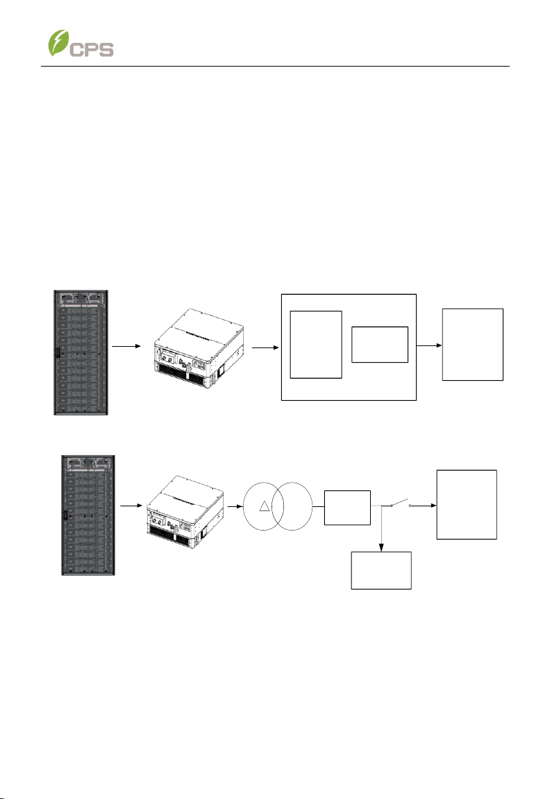
2.1 PCS for energy storage systems ................................................ 8
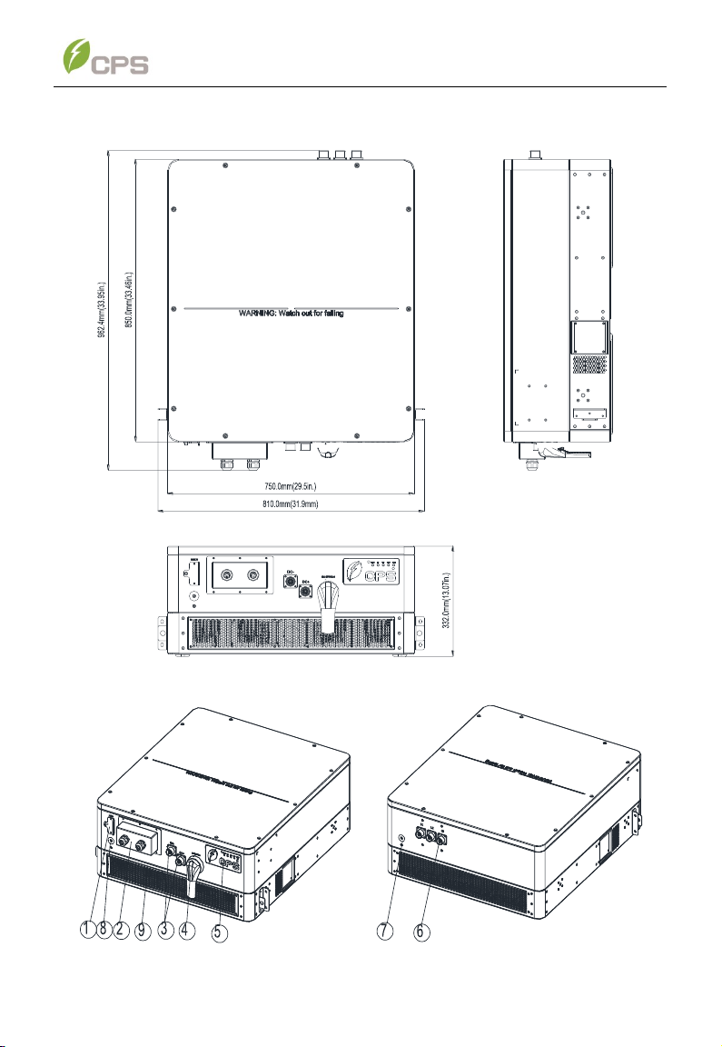
2.2 Appearance and Dimensions ...................................................... 9
2.3 Nameplate ..................................................................................... 10
2.4 Product features............................................................................11
2.5 Protection functions......................................................................11
2.6 Circuit structure design................................................................11
3Mechanical Installation ............................................................................-13
3.1 Unpacking for Inspection............................................................. 13
3.2 Installation Precautions ............................................................... 13
3.3 Installation Requirements............................................................ 14
3.3.1 Environment Requirements............................................. 14
3.3.2 Installation Modes ............................................................ 14
3.3.3 Space Requirements ........................................................ 14
3.4 Installation process...................................................................... 16
3.4.1 Prepare the mounting bracket......................................... 16
3.4.2 Lifting Instruction ............................................................. 18
3.4.3 Install the PCS .................................................................. 21
4Electrical Installation................................................................................-22
4.1 Cables specifications................................................................... 22
4.2 Tools Required and Torque Values ............................................. 22
4.3 Connection interface.................................................................... 22
4.4 AC and Ground connection ......................................................... 24
4.5 DC and Ground connection ......................................................... 25
4.6 Communication connection ........................................................ 26
4.6.1 Communication interfaces and cards............................. 26
4.6.2 LINKIT module Installation .............................................. 31
4.7 Connect with a CPS FlexOM Gateway ........................................ 32
5Commissioning.........................................................................................-37
5.1 Pre-commissioning Checklist ..................................................... 37
5.2 Commissioning steps .................................................................. 37
6User Interface............................................................................................-38
6.1 LED lights and indication............................................................. 38
6.2 Mobile application functions ....................................................... 39
6.2.1 APP download................................................................... 39
6.2.2 APP Setting ....................................................................... 39
6.2.3 Main menus of APP page................................................. 46
6.3 Web application functions ........................................................... 89
6.3.1 Ethernet connection and setting..................................... 89
6.3.2 Web application setting ................................................... 91

Table of Contents
2/ 135
6.3.3 Main menus of web page ................................................. 94
6.4 Modbus function ...........................................................................111
6.4.1 Modbus RTU ......................................................................111
6.4.2 Modbus TCP ......................................................................112
7Operation...................................................................................................114
7.1 Start-up and shut down ................................................................116
7.1.1 Start-up ...........................................................................116
7.1.2 Shutdown...........................................................................118
7.2 Operation modes...........................................................................119
7.3 Anti-islanding safety function ..................................................... 120
8Maintenance and troubleshooting ..........................................................121
8.1 Regular maintenance ................................................................... 121
8.2 Service and Replace..................................................................... 121
8.2.1 Replace cooling fans........................................................ 121
8.2.2 Replace the PCS ............................................................... 124
8.3 Troubleshooting ........................................................................... 125
9Technical Data .........................................................................................130

Table of Contents
3/ 135
Revision History
Rev No.
Section
Rev Date
Description
1.0
N/A
May 2022
Initial release
1.1
Aug. 2022
Implemented feedback
1.2
Oct. 2022
Updated AC&DC wiring terminals
1.3
4.6
Feb. 2023
Updated communication section
Updated packing list
1.4
3.4.1
Mar. 2023
Revised the mounting bracket
section
1.5
Apr. 2023
Improved overall
Revised product name
1.6
3.2
3.3.1
4
May 2023
Added installation precautions
Updated environment
requirements
Added CAN bus specification

Before You Start
1-4 / 135
Before You Start…
This manual contains important information regarding installation and safe operation
of this unit. Be sure to read this manual carefully before using the product.
Thank you for choosing CPS ECB200KTL/US-800 Bidirectional Power Conversion
System (hereinafter shortly referred to as “PCS”). The PCS is a high-performance
and highly reliable product specifically designed for USA market.
If you encounter any problems during installation or operation of this unit, first check
the user manual before contacting your local dealer or supplier.
Instructions inside this user manual will help you solve most installation and operation
difficulties. Contact your local representative if the problem persists.
Please keep this user manual on hand for quick reference.

IMPORTANT SAFETY INSTRUCTIONS
5/ 135
1 IMPORTANT SAFETY INSTRUCTIONS
(SAVE THESE INSTRUCTIONS)
Please read this user manual carefully before product installation. CPS
reserves the right to refuse warranty claims for equipment damage if the user
fails to install the equipment according to the instructions in this manual.
1.1 Warnings and symbols in this document
Before reading the manual, please pay attention to several very important safety
warnings. Being familiar with them can make you safer in operation and maintenance.
DANGER:
DANGER indicates a hazardous situation which, if not avoided, will result
in death or serious injury.
DANGER!
DANGER indique une situation dangereuse avec un niveau de risque
élevé qui, si elle n'est pas évitée, entraînera la mort ou des blessures
graves.
WARNING:
WARNING indicates a hazardous situation which, if not avoided, could
result in death or serious injury.
ATTENTION!
AVERTISSEMENT indique une situation dangereuse avec un niveau de
risque moyen qui, si elle n'est pas évitée, pourrait entraîner la mort ou
des blessures graves.
CAUTION:
CAUTION indicates a hazardous situation which, if not avoided, could
result in minor or moderate injury.
AVERTIR!
ATTENTION indique une situation dangereuse avec un faible niveau de
risque qui, si elle n'est pas évitée, pourrait entraîner des blessures
mineures ou modérées.
NOTICE:
NOTICE indicates a hazardous situation which, if not avoided, could
result in equipment working abnormally or property loss.
AVIS!
indique une situation dangereuse qui, si elle n'est pas évitée, pourrait
entraîner un fonctionnement anormal de l'équipement ou la perte de
biens.
INSTRUCTION:
INSTRUCTION indicates important supplementary information or
provides skills or tips that can be used to help you solve a problem or
save your time.

IMPORTANT SAFETY INSTRUCTIONS
6/ 135
1.1 Markings on the product
Symbols
Meanings
WARNING:
Risk of Electric Shock.
ATTENTION:
Risque de choc electrique.
CAUTION:
Risk of electric shock from energy stored in capacitor.
Do not remove cover until 5 minutes after disconnecting all
sources of supply.
ATTENTION:
Risque de choc électrique à partir d´énergie stockée dans les
condensateurs.
Retirer le couvercle du boîtier au moins 5 minutes après avoir
débranchétoutes les sources d´approvisionnement.
CAUTION:
Hot surfaces.
To reduce the risk of burns. Do not touch.
ATTENTION:
Surface chaude.
Pour réduire le risquéde brûlures ne pas toucher.
For more details, please see the user manual.
Pour plus de détails, veuillez consulter le manuel d'utilisation.
WARNING:
For continued protection against risk of fire, replace only with
same type and ratings of fuse.
Refer to instruction manual for details.
ATTENTION:
Pour continuer d'assurer la protection contre les risques
d'incendie, il faut remplacer les fusibles de même type et
courant.
Reportez-vous au manuel d'instructions pour plus de détails.
IMPORTANT!
Indique des informations supplémentaires importantes ou fournit des
compétences ou des conseils qui peuvent être utilisés pour vous aider à
résoudre un problème ou vous faire gagner du temps.

IMPORTANT SAFETY INSTRUCTIONS
7/ 135
EARTH GROUND!
This symbol marks the location of a grounding terminal, which
must be securely connected to the earth through the PE
(protective earthing) cable to ensure operational safety.
MISE À LA TERRE !
Ce symbole marque l'emplacement d'une borne de mise à la
terre, qui doit être solidement connectée à la terre via le câble
PE (mise à la terre de protection) pour assurer la sécurité de
fonctionnement.
FCC RULES
This product complies with the part 15 of FCC rules.
RÈGLES DE LA FCC
Ce produit est conforme àla partie 15 des règles de la FCC.
RoHS SYMBOL
In accordance with 2011/65/EU regulations, PCS imposes
restrictions on the use of specific hazardous substances in
electrical and electronic equipment.
SYMBOLE RoHS
Conformément à la réglementation 2011/65/UE, PCS impose
des restrictions sur l'utilisation de substances dangereuses
spécifiques dans les équipements électriques et électroniques.
CSA Certification
The PCS has passed CSA Certification.
CSA Certification
Cet onduleur a passéla certification CSA.
Phase information of the PCS.
Information de phase de l'onduleur.

Overview
8/ 135
2 Overview
2.1 PCS for energy storage systems
The PCS is suitable for large-scale energy storage applications. A typical energy
storage system with this product generally consists of battery modules, PCS (this
product), energy management systems (EMS) and AC power distribution equipment
(Figure 2-1a /Figure 2-1b). It is used to convert DC power from battery modules to
AC with the same frequency and phase as the AC grid.
The PCS is UL 1741-SB certified to IEEE 1547-2018 standards, and offers Volt-Ride
Thru, Freq-Ride Thru, Ramp-Rate, PF, Volt-Var, Freq-Watt, Volt-Watt and other grid-
support functions.
AC Grid
Bidirectional
electric meter
AC power
distribution
equipments
BATTERY
Figure 2-1a grid-tied energy storage system example
AC Grid
Bidirection
al electric
meter
BATTERY
Local
LOAD
Y
Figure 2-1b off-grid energy storage system example
When the storage system is in off-grid mode and has unbalanced single phase loads,
an external isolation transformer is necessary. If the power grid is lost, the contactor
on the grid side must be disconnected, and the PCS supplies power to the local load.

Overview
9/ 135
2.2 Appearance and Dimensions
Figure 2-2 Dimensions of CPS ECB200KTL/US-800
Figure 2-3 Appearance of the PCS

Overview
10 / 135
Main components on the inverter enclosure:
No.
Name
Function
1
LINKIT module interface
Connect LINKIT module
2
Cover of communication
interface
Seal the communication interface
3
DC connector
Connect DC cable
4
DC Switch
Turn on/off the DC side power supply
5
LED indicator
Indicates operation status of the PCS
6
AC connector
Connect AC cable
7
AC PE terminal
Connect AC PE (protection earthing)
cable
8
DC PE Terminal
Connect DC PE cable
9
Fans
Forced cooling of the PCS
Table 2-1 Product Components
2.3 Nameplate
Serial Number
This device complies
with part 15 of the
FCC Rules
Model No.: CPS ECB200KTL/US-800
Discharge Mode
Input operating voltage range: 875-1500Vdc
Max. input current(dc): 218A
Max. continuous output current(ac): 145A
Max. continuous output power: 200kVA
Nominal AC output voltage: 800Vac 3~
Nominal power frequency: 60Hz/57-63Hz
AC current THD: <3%
Power factor: >0.99(adj.±0.8)
Max. efficiency: 98.0%
CEC efficiency: 97.0%
Standalone output voltage: 704-880Vac
Operating temperature range: -30°C-+60°C
Protective class: Class
Type of enclosure: TYPE 4X
Made in xxxx
Energy Storage Inverter
(Grid Support Non-Isolated)
Serial Number
This device complies
with part 15 of the
FCC Rules
RoHS
UL 1741
Cert.to CSA Std.C22.2 No.107.1
Charge Mode
Input operating voltage range: 704-880Vac
Nominal output voltage: 1085V
Max. input current(ac): 145A
Charging output voltage range(dc): 875-1500Vdc
Figure 2-4 Nameplate of CPS ECB200KTL/US-800

Overview
11 / 135
2.4 Product features
High conversion efficiency:Advanced 3-level conversion technology; Max.
discharge efficiency: 98%, Max. charge efficiency: 97%;
Flexible grid support capabilities: 2 selectable grid standards; adjustable
reactive power: ±0.8, remote curtailment;
Flexible communication: Supports standard Modbus (RTU, TCP, ASCII) and
CANbus (extended frame, data frame) communications to ensure compatibility
with 3rd party monitoring and control systems;
Wide DC input voltage range :Operating DC input voltage range: 875-
1500Vdc; Max DC input voltage: 1500V.
Charge and discharge: The PCS can charge/discharge the batteries from/to
the grid.
Outdoor rating: NEMA Type 4X protection degree meets outdoor application;
Grid-tied/off-grid capability: Support grid-tied and off-grid switching. If the off-
grid mode is set in the auto-switch mode, when the power grid has failed, the
PCS will be automatically switched from grid-tied to off-grid mode.
2.5 Protection functions
Reverse-polarity protection of DC input
Short circuit protection
AC output voltage and frequency monitoring
AC insulation resistance monitoring
Monitoring of DC injection into AC output
Anti-islanding protection
Input and output over-voltage protection
Input over-current protection
Environmental temperature monitoring
Battery temperature monitoring
LVRT (Low-voltage ride-through) and HVRT (High-voltage ride-through)
2.6 Circuit structure design
Basic schematic diagram of the PCS is shown below. The input of the batteries
passes through contactors and pre-charge circuit. The output of the PCS converts
the DC voltage to 3-phase AC voltage. An output filter is employed to remove the
high-frequency harmonics and reduce THD (Total Harmonic Distortion). Then the 3-
phase AC voltage is passed through two-stage relays and EMI wave filter to produce
high quality AC power.

Overview
12 / 135
Figure 2-5 Schematic diagram of the PCS

Mechanical Installation
13 / 135
3 Mechanical Installation
3.1 Unpacking for Inspection
Below is the installation procedure for the PCS. Please read carefully and install the
product step-by-step.
Before installation, please check that the following items are included in the package.
Table 3-1 Main items
No.
Item
Qty
Note
1
CPS ECB200KTL/US-800
1
PCS
2
Accessory kit
1
Contains all necessary accessories
The Accessory Kit contains items listed below.
Table 3-2 ECB200KTL Accessories
No.
Item
Qty
Note
(1)
10-pin terminal
4
For Communication cables
(2)
4-pin terminal
1
For output dry node cable
(3)
M6X16 screw, Grade: A2-50
8
For fastening PCS
(4)
95mm2 Connector, black
4
For DC- and L1,L2,L3 cable
connection
(5)
95mm2 Connector, orange
1
For DC+ cable connection
(6)
LINKIT (Optional)
/
For Wi-Fi communication
3.2 Installation Precautions
Check that the product environmental specifications (protection degree,
operating temperature range, humidity and altitude, etc.) meet the
requirements of the specific project location;
Make sure that the power grid voltage is within allowed range: 422~528 VAC;
Ensure that the local electricity supply authority has granted permission to
connect to the grid;
Installation personnel must be qualified electricians or people who have
received professional training;
Wear and use PPE (personal protective equipment) during installation and
cable connection, such as safety shoes, safety gloves, safety helmet, etc.
INSTRUCTION:
The items in the accessory kit table above are for the standard
configuration.

Mechanical Installation
14 / 135
Sufficient space is provided to allow the PCS cooling system to operate
normally;
Install the PCS away from flammable or explosive substances;
Avoid installing the PCS in locations that exceed the temperature limits
specified in the PCS data sheet to limit undesirable power loss;
Do not install the PCS near any electromagnetic source which can
compromise the normal operation of electronic equipment;
The characteristics of salt mist are easily affected by factors such as
seawater, sea breeze, precipitation, relative humidity, terrain, and forest
range near the coast. Therefore, inverters should not be installed outdoors
in salt affected areas (within 500m from the coast).
3.3 Installation Requirements
3.3.1 Environment Requirements
The PCS is designed for large-scale energy storage application, it shall be installed
and used together with energy storage system. The PCS can be installed outdoor
and is able to withstand direct sunlight, rain or snow. However, to avoid power
derating due to high or sudden temperature fluctuations, it is recommended to install
the PCS under a roof or sunshade/rain-shed. Direct outdoor installation does not
impact warranty.
3.3.2 Installation Modes
The PCS shall be positioned on the mounting bracket horizontally and fastened with
appropriate screws firmly to avoid tilting and shifting.
3.3.3 Space Requirements
The following installation space clearance shall be met according to different
installation scenarios:
Install a single PCS.
The PCS shall be installed with at least 1 m (39.4 in.) of clearance to its left or
right side to leave room to remove fans from one side of the PCS if
maintenance is required. The other side (left or right) shall be installed at least
50 mm (1.97 in.) from the nearest object. The front and rear sides of the PCS
shall be installed at least 500 mm (19.7 in.) from the nearest object and shall
not be installed within the vicinity of any heat sources. See Figure 3-1 for more
information.
Figure 3-1 Install a single PCS on mounting bracket

Mechanical Installation
15 / 135
Install several PCSs by stacking on one mounting bracket (the bracket is not
included in the package and the diagram is for illustration purposes).
In addition to all the above distance requirements, a minimum distance of
50mm shall be kept between two adjacent PCSs to ensure good ventilation.
Figure 3-2 Stack installation on one mounting bracket
Position two sets of mounting brackets with stacked PCSs side by side.
In this scenario, a minimum distance of 1000 mm (39.37 in.) shall be reserved
on both sides of the mounting brackets so that the fan brackets can be pulled
out from their left side or the right side completely without any obstruction. In
the same way, a minimum distance of 50 mm shall be kept between two
adjacent stacked PCSs to ensure good ventilation.
Figure 3-3 Two sets of mounting brackets with stacked PCSs
NOTICE:
The Weight of one PCS is about 120kg (≈265 pounds).
Make sure mounting brackets can bear the total weight of all stacked
PCSs to avoid bracket damages and PCS falling off!
Consult the after-sale personnel for any special scenarios.

Mechanical Installation
16 / 135
3.4 Installation process
3.4.1 Prepare the mounting bracket
To illustrate mounting steps, the mounting bracket shown in figure 3-4 will be used as
an example.
Figure 3-4 Reference mounting bracket assembly
No.
Component name
Qty
1
Vertical beam
6
2
Horizontal beam
3
3
Front mounting bracket
2
4
Rail bracket
2
5
Back plate
1
Table 3-3 Accessories of the reference mounting bracket
The assemble procedures of reference mounting brackets are as follow:
1. Assemble three horizontal beams (2) on the three groups of vertical beams
(1) in sequence and pre-tighten them with four M6x16 screws on every end
of the horizontal beam.
2. Position two rail brackets (4) onto the two ends of the three horizontal
beams (1), align their screw holes and pre-tighten them with six sunk
screws.
NOTICE:
The side guards of the two rail brackets shall be facing outside.

Mechanical Installation
17 / 135
3. Pre-tighten the two endplates of the back plates onto the rear vertical
beams with six M6x16 screws on each endplate. The hole dimensions of
the back plate can be found in figure 3-5.
Figure 3-5 Hole dimensions of the back plate
4. Pre-tighten the two endplates of the back plates onto the rear vertical
beams with six M6x16 screws on each endplate. The hole dimensions of
the two front mounting brackets can be found in figure 3-6.
Figure 3-6 Hole dimensions of the front mounting brackets
5. Tighten all the screws with No.3 Phillips head screwdriver, torque value:
6-7 Nm (4.4-5.2 lb-ft).

Mechanical Installation
18 / 135
3.4.2 Lifting Instruction
Lift the PCS to the height that its bottom is aligned with the rail bracket so that it can
be placed onto the rail bracket smoothly. This operation can be achieved by the
following three lifting options shown below.
Manual lifting: at least three people are needed to properly lift and support
from the base surface (see figure 3-7);
Figure 3-7 Manual lifting from the base surface
Rope lifting: Operate as following steps.
(1) Screw two M10 eyebolts (non-standard) in two opposite sides of the
PCS.
Figure 3-8 Screw two M10 eyebolts

Mechanical Installation
19 / 135
(2) Use two ropes to lift the device with the aid of aforementioned eyebolts
and the two lifting holes on the front mounting bracket, see figure 3-9 for
details.
Figure 3-9 Rope lifting with eyebolts and lifting holes
NOTICE:
The length of ropes shall make sure the angle between two sling
ropes is less than 60 degree, thus avoiding to damage or bend the
enclosure edges.
Consult the after-sale personnel for any special scenarios.
Hoist the bottom of the PCS with forklift
(1) Find the center of gravity of the PCS as shown below.
Figure 3-10 Center of gravity of the PCS
Table of contents