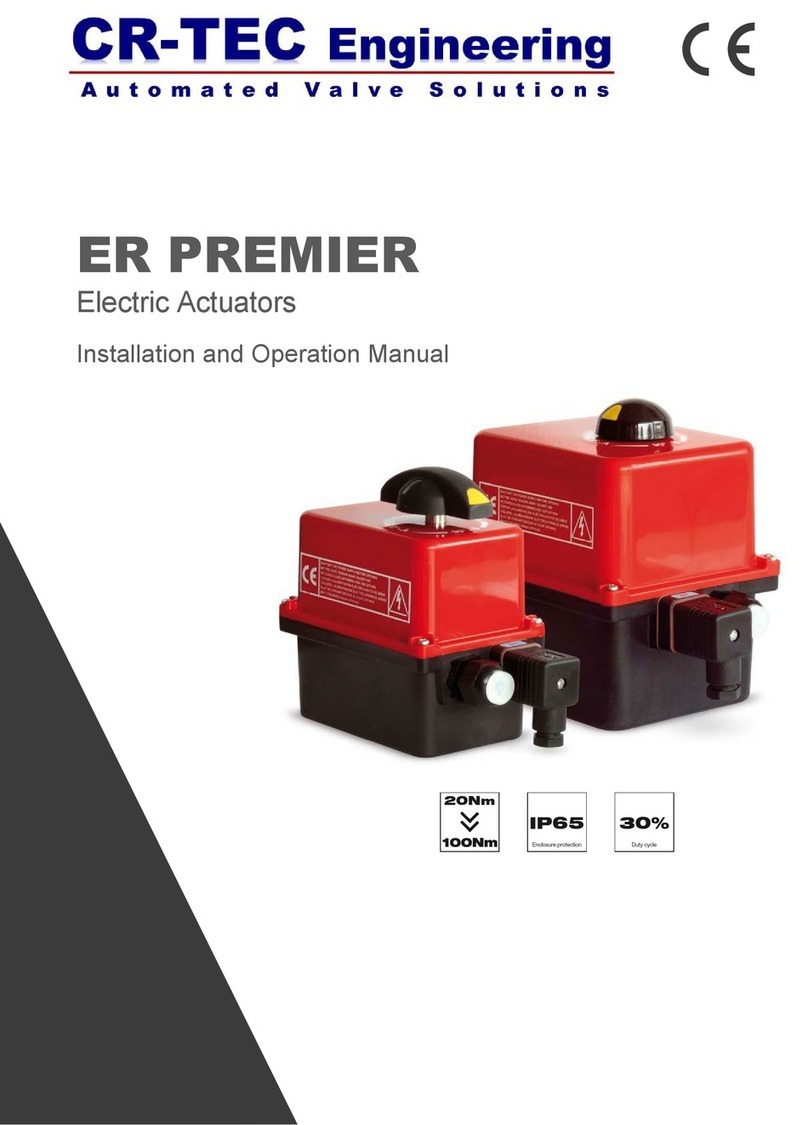
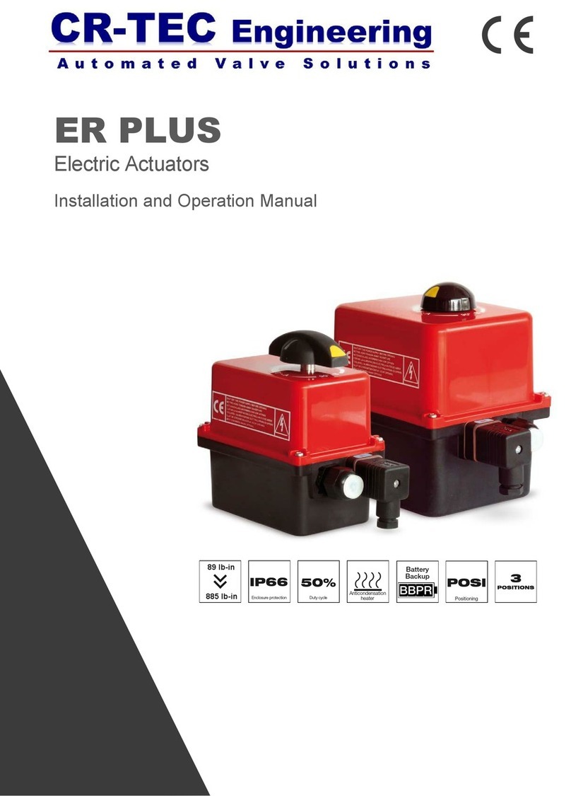
CR-Tec CR50S Guide

Installation, Operation, & Maintenance Instructions
CR50S & CR50S Modulating
Compact Electric Actuator

Table of Contents
1.Pre-Installation Inspection
2.Storage
3.Structure of Actuator
4.Specifications
5.Dimensions
6.Actuator Installation and Set-up
A. Valve mounting
B. Wiring
C. Limit switch setting
D. Manual operation
7.Troubleshooting
8.Maintenance
A. Lubrication
B. Regular Operation
C. Maintenance
9.Instruction of PCU Card
A. Layout of PCU
B. Specifications of PCU
C. Mode Setting
D. Modulating Set-up
CR-TEC Engineering Inc. • info@crtec.com • www.crtec.com • 203-318-9500

1. Pre-Installation Inspection
A. Actuator should be selected with 30% safety factor of the maximum torque of the valve when selecting
the actuators.
B. Check for correct voltage prior to wiring.
C. Turn power off before servicing or for maintenance purpose.
D. Use sealant to seal conduit connections after wiring to prevent dusting or water contamination.
E. The angle of electric actuator installation must be between 0~180 degree.
Do not install upside down or below the horizontal.
F. When more than one electric actuator needed to operate simultaneously, please connect with the individual
cables.
G. When connecting the power supply, 1mm², 18AWG or more cable should be used and it shall be connected
through over-current protection device(circuit breaker) at 125% or more of the rated current.
H. Please connect the ground wire.
I. Not intended for vacuum spaces and avoid installing (near)explosive atmospheres.
J. To avoid functional failure caused by statics, do not touch any components on the PCB with metal tools or etc.
2. Storage
If you actuator cannot be installed immediately store it in a dry place, it must be protected from excess
moisture, dust and weather until you are ready to connect incoming cables.
If the actuator has to be installed but cannot be cable, please don’t remove the plastic cable entry plugs.
When the actuator has to be cable, it is recommended that to replace with suitable water-proof plugs and
have IP67 protection
Warning : Use caution when working in, with, or around valves and actuators.
High pressures, forces, voltages and flammable media can be present.
Warning : Failure to follow instructions for proper electrical wiring, storage, set-up and
maintenance may cause serious injury, damage equipment, or void warranty.
CR-TEC Engineering Inc. • info@crtec.com • www.crtec.com • 203-318-9500
Page 3

Motor
Limit switch cam
Main P.C.B
Limit switch
Indicator
3. Structure of Actuator
Top cover
Base body
Indicator
Cable entry
Manual handle-wheel
Chamber of
terminal block
Manual lever
Bottom flange
F03, F04 & F05 Bottom bore
14X14 Double square
CR-TEC Engineering Inc. • info@crtec.com • www.crtec.com • 203-318-9500
Page 4

4. Specification
Travel Angle ±5% 90°
Supplying power ±10% 95 to 245 VAC 50/60Hz (1Ph), 24 VAC 50/60Hz, & 24 VDC
Motor S2 30 Min. (Modulating: S4 50% 1200 Start/hour)
Limit switch 2 X Open/Close SPDT (250VAC 3A , 125VAC 5A)
Auxiliary limit switch 2 X Open/Close SPDT (250VAC 3A , 125VAC 5A)
Manual override Handle-wheel with manual lever (17 Turns)
Space heater 1W
Ambient temperature -4° F to 140° F (-20° C to +60°C)
Ambient humidity 90% Rh Max. (non-condensing)
Cable entry 2 X PF ½”
Materials Aluminum Die-Casting
Bottom Flange(ISO5211 ) F03, F05 & F07
Bottom Bore 14 X 14 Double square (11X11mm available)
Operation Time (No Load) 13sec.
Indicator Dome type mechanical indicator
Power Consumption - Idle
Power Consumption - Operation 20 Watt Max
1.5 Watt Max
Wire Size 12 to 18 AWG (Use Solid Wires)
Enclosure Weather-proof IP67
CR-TEC Engineering Inc. • info@crtec.com • www.crtec.com • 203-318-9500
Page 5

5. Dimension
CR-TEC Engineering Inc. • info@crtec.com • www.crtec.com • 203-318-9500
Page 6

6. Actuator Installation and Set-up
A. Valve mounting
Mounting is most easily done with the valve shaft pointing vertically upward, but the actuator may be
mounted in any position.
CR50S actuators are supplied with a female drive output.
The bottom bolt pattern is drilled as F03, F05 & F07 according to ISO5211.
It is mandatory that the actuator be firmly secured to a sturdy mounting bracket or directly mounted to
the valves ISO mounting pad. High tensile bolts or studs with spring locking washers must be used.
The valve output stem must be in line with the actuator output drive to avoid side loading of the stem.
To prevent backlash, no flexibility in the mounting bracket arrangement should be present.
B. Wiring
a. Precaution
(1) Cable entries are machined with PF 1/2 and sealed by plug before delivery.
(2) Please remain the plug as it is if user doesn’t use both cable entries.
(3) Please make sure to seal the entries by using rubber or metallic packing after wiring,
so that water or other foreign material may not come in.
(4) If suitable cable connection is not used for wiring, factory won’t guaranty the performance.
b. Electrical wiring
(1) Check if the electrical specification like as power, wiring or etc are correct.
(2) Wiring diagram is to be supplied together with the actuator.
(3) Do the wiring as per the given wiring diagram, such as power, control power, internal wiring and
ground.
(4) Make sure to supply the electric power to the heater to keep inside of the actuator clean and
dry for anti-condensation.
(5) Make sure to check if wiring to the terminal is connected firmly.
(6) Make sure that one relay operates one actuator only (Can’t operate two or more actuators).
(7) Make sure to clean inside of the actuator and no foreign material inside.
(8) After the testing, check that all cable glands are correctly tightened.
Applicable cable glands should be selected to meet the application’s condition.
It is recommended to use the grade of IP67 cable gland.
Make sure all incoming power is disconnected before wiring!!!
c. How to connect
“Pluggable connection system” terminal block is installed for saving
time of wiring job and it is make the wiring job easy or simple
(1) Remove cable plug and open cover of chamber of terminal block
(2) Disassemble female connector from terminal block
(3) Insert wires through cable entry.
(4) Connect wires to female connector according to wiring diagram
(5) Plug female connector in male header
CR-TEC Engineering Inc. • info@crtec.com • www.crtec.com • 203-318-9500
Page 7

d. Wiring Diagram
1
GND
FREE VOLTAGE AC 3 WIRE
NEUTRAL (N) LINE (L)
NEUTRAL (N)
CLOSE (L)
OPEN (L)
CLOSE SWITCH (N/C)
POSITION OUTPUT SWITCHES
CLOSE SWITCH (N/O)
OPEN SWITCH (N/C)
OPEN SWITCH (N/O)
COMMON
GND
NEUTRAL (N) LINE (L)
NEUTRAL (N)
CLOSE (L)
OPEN (L)
CLOSE SWITCH (N/C)
POSITION OUTPUT SWITCHES
CLOSE SWITCH (N/O)
OPEN SWITCH (N/C)
OPEN SWITCH (N/O)
COMMON
Free Voltage AC 4 WIRE (ON - OFF)
GND
24V AC/DC 3 WIRE
24 VAC (N)
24 VDC (+)
CLOSE
OPEN
CLOSE SWITCH (N/C)
POSITION OUTPUT SWITCHES
CLOSE SWITCH (N/O)
OPEN SWITCH (N/C)
OPEN SWITCH (N/O)
COMMON
24V AC/DC 3 WIRE (ON - OFF)
VOLTAGE (L)
+ -
24 VAC (L)
24 VDC (-)
24 VAC (L)
24 VDC (-)
24 VAC (L)
24 VDC (-)
FREE VOLTAGE AC 3 WIRE
2345 6 78 9 10
1 2 3 4 5 6 7 8 9 10
1 2 345 6 78 9 10
Free Voltage AC 3 WIRE (ON - OFF)
CR-TEC Engineering Inc. • info@crtec.com • www.crtec.com • 203-318-9500
Page 8

d. Wiring Diagram
GND
FREE VOLTAGE AC
MODULATING
NEUTRAL (N)
POSITION OUTPUT
SWITCHES
CLOSE SWITCH (N/O)
OPEN SWITCH (N/O)
COMMON
Free Voltage AC (Modulating)
GND
24V AC/DC 4 WIRE
24 VAC (N)
24 VDC (+)
CLOSE
OPEN
CLOSE SWITCH (N/C)
POSITION OUTPUT SWITCHES
CLOSE SWITCH (N/O)
OPEN SWITCH (N/C)
OPEN SWITCH (N/O)
COMMON
+ -
24 VAC (L)
24 VDC (-)
24 VAC (L)
24 VDC (-)
24 VAC (L)
24 VDC (-)
LINE (L)
INPUT
SIGNAL
+ - + -
OUTPUT
SIGNAL
GND
POSITION OUTPUT
SWITCHES
CLOSE SWITCH (N/O)
OPEN SWITCH (N/O)
COMMON
24V AC/DC (Modulating)
INPUT
SIGNAL
+ - + -
OUTPUT
SIGNAL
24 VAC (N)
24 VDC (+)
24V AC/DC
MODULATING
+ -
24 VAC (L)
24 VDC (-)
1 2 345 6 78 9 10
1 2 3 4 5 6 7 8 9 10
1 2 345 6 78 9 10
24V AC/DC 4 WIRE (ON - OFF)
CR-TEC Engineering Inc. • info@crtec.com • www.crtec.com • 203-318-9500
Page 9

d. Wiring Diagram - Optional DIN Connector
3-Position Switch Control (Open/Close)
N
-
Open Close
Ph
+
GND
2
3
1
POWER SUPPLY : 3P+T DIN43650 CONNECTOR
SUGGESTED CUSTOMER WIRING
CR-TEC Engineering Inc. • info@crtec.com • www.crtec.com • 203-318-9500
DIN Wiring for Modulating Option
N
-
Ph
+
GND
2
3
1
Page 10

Aux. Close Limit Switch
Close Limit Switch
Open Limit Switch
Open Limit Switch Aux.
Close limit switch cam
Open limit switch cam
M4 hexagon socket head screw
C. Limit switch setting
(1) No need to adjust because Limit Switch is set at factory.
(2) In case that Limit Switch Cam re-adjust at site, operate the actuator manually to the close(open) position.
· Loosen the cam adjustment screw in the Close(Open) limit switch cam.
· Rotate the cam in a clockwise(counter-clock wise) towards the limit switch lever until cam double-
clicks on the switch.
· Tighten the cam screw
D. Manual operation
(1) Disconnect Power
(2) Rotate lever 90⁰ as the right picture.
(3) Rotate handle-wheel for open or close
(4) After manual operation or supplying
power, place the lever back in place !!!
※When turning the lever, simultaneously turn the
handle slightly in both directions.
7. Trouble Shooting
A. Actuator does not respond
(1) Check that the voltage matches the rating on the actuator
nameplate.
(2) Verify the line of power supplying to the actuator
(3) Check internal wiring against actuator wiring diagram
(4) Check limit switch cams
B. Actuator is receiving power but does not operate
(1) Check if the valve force is bigger than the torque of actuator
(2) Check limit switches and cams
(3) Check internal wiring
(4) Verify coupler/bracket are correctly installed
(5) Verify the actuator against valve rotation
C. Valve only opens or closes partially with motor
(1) Limit switch incorrectly set
(2) Over torque : Incorrectly sized actuator
(3) Jammed valve
(4) Damaged or bent valve stem
Auto mode Manual mode
CR-TEC Engineering Inc. • info@crtec.com • www.crtec.com • 203-318-9500
Page 11

8. Maintenance
A. Lubrication
Lubrication is already done by factory and generally no need field lubricate.
In places such as very dry condition below 15% Rh or high temperature higher than 30°C,
it is required to lubricate every two years through Grease nipple.
B. Regular operation
Even if you do not use an actuator, electrical power always should be supplied to actuator and it is
recommended to operate actuator once a week
C. Maintenance
Actuator should be thoroughly checked at least once a year.
· Disconnect all power to actuator.
· Check that all external bolting and mounting to the valve is secure and aligned.
· Check to see that conduit connections are installed properly and are dry.
· Open Electrical Enclosure.
· Visually inspect for cleanliness and any electrical or mechanical damage.
· Inspect for excess moisture and condensation inside the electrical enclosure.
· Confirm that wiring is insulated, connected and terminated properly.
· Check enclosure O-ring seals and verify that the O-ring is not pinched between the flanges.
· Visually inspect during open/close cycle.
CR-TEC Engineering Inc. • info@crtec.com • www.crtec.com • 203-318-9500
Page 12

9. Instruction of PCU Card
A. Layout of PCU
Zero/Span volume
Auto buttonManual button
Deadband
LED signal lamp
Mode setting
B. Specification of PCU
Supplying Electric Power 95 to 245 VAC 50/60Hz (1Ph), 24 VAC 50/60Hz, & 24 VDC
Input Signal 4~20mA, 0~10V, 2~10V
Output Signal 4~20mA, 0~10V, 2~10V
Insulation Resistance 500V DC, 50Mohm
Space Heater 1W
Input Position Conversion Accuracy ± 1%
Output Position Conversion Accuracy ± 1%
Ambient Temperature -4° F to 140° F (-20° C to +60°C)
Ambient Humidity 90% RH Max. (non-condensing)
CR-TEC Engineering Inc. • info@crtec.com • www.crtec.com • 203-318-9500
Page 13

operate 3 times around 0~10% range in close
position and operate 3 times around 90~100% range
in open position.
※Actuator do not respond to input signal or manual
mode during auto mode.
※Actuator do not respond to input signal
during manual mode.
D. Modulating Set-Up
1. Auto mode
·DIP S/W “1” is OFF.
·Push “Auto button” around 3seconds
-To minimize hunting and improve resolution,
2. Manual mode
·DIP S/W “1” is ON.
·For open, push “OP” button and push “CL” for close. CL OP
C. Mode setting (Setting of Dip switch)
AT
INPUT OUTPUT FAIL MODE
SW-1 SW-2 SW-3 SW-4 SW-5 SW-6 SW-7
ON OFF MANUAL
OFF ON AUTO
OFF OFF OFF OFF ON 4~20mA
OFF ON OFF OFF ON 2-10VDC
ON ON ON ON OFF 0-10VDC
OFF OFF STOP
ON OFF OPEN
OFF ON CLOSE
CR-TEC Engineering Inc. • info@crtec.com • www.crtec.com • 203-318-9500
Page 14

6. Dead band setting
Status FT(RED) CL(YEL) OP(GRE) AT(RED)
Normal operation ON
Auto setting ON ON ON
Opening ON
Closing ON
It is set to adjust the accuracy of the input signal.
0 step : Set as factory default
1 step : 0.1mA
Increase by 0.05mA for each step(2 ~ F step)
If the accuracy is too high, it could cause "HUNTING".
HUNTING means the actuator doesn’t stop at the right position
and repeats open or close to find the right position.
HUNTING might be the reason of the motor burning and damages of the potentiometer and PCU card.
3. Setting of In/Output signal
4. Adjustment of Output signal
Adjust zero or span volume switch to meet the exact value
of output signal in accordance with input signal value.
5. LED Signal Lamp
2) LED for error
Error LED Status
Potentiometer fault LED1 & LED2 ON
LED3 & LED4 Blink every 0.5 sec
Broken input signal LED1 & LED2 ON
SIGNAL INPUT OUTPUT
SW-1 SW-2 SW-3 SW-4 SW-5
4~20mA OFF OFF OFF OFF ON
2-10VDC OFF ON OFF OFF ON
0-10VDC ON ON ON ON OFF
CR-TEC Engineering Inc. • info@crtec.com • www.crtec.com • 203-318-9500
1) LED
Page 15

CR-TEC reserves the right to change or remove products or services from its range at any time and without prior notification or obligation. CR-TEC does not
assume any liability for consequences resulting from the use of this document. There is no guarantee that the information provided here is complete, accurate or
up to date.
CR-TEC Engineering Inc.
15 Orchard Park Road, Unit 18
Telephone 203-318-9500 • Fax 203-245-2575
[email protected] • www.crtec.com
Catalog 2020 (Verr.17-A0-001) © CR-TEC Engineering Inc.
CR-TEC Engineering Inc.
This manual suits for next models
1
Table of contents
Other CR-Tec Controllers manuals
Popular Controllers manuals by other brands

Traxon
Traxon Butler S2 Setup manual
Malmbergs
Malmbergs 99 170 24 instruction manual
National Instruments
National Instruments sbRIO-9607 user manual
Victron energy
Victron energy BlueSolar MPPT 100/30 user manual

AfterBurner
AfterBurner GPIO CAPABILITY user manual
Extech Instruments
Extech Instruments 48VFL instruction manual
