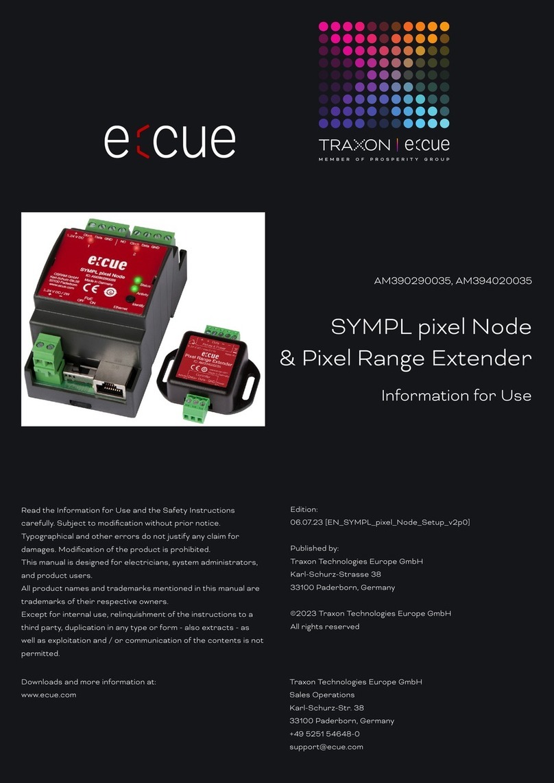
Traxon Butler S2 User guide

Butler S2
Setup Manual

Published by/Herausgegeben von
Traxon Technologies Europe GmbH
An OSRAM Business
Karl Schurz-Strasse 38
Paderborn, Germany
Setup Manual Butler S2
Edition 18.01.13
©2012, Traxon Technologies Europe GmbH
All rights reserved/Alle Rechte vorbehalten
Comments and corrections:/Kommentare und Korrekturen an:

Table of Contents
English ......................................................................5
Safety instructions .................................................................................... 6
Delivery content ........................................................................................ 6
Optional accessories ...........................................................................6
Overview ................................................................................................... 7
Transport .................................................................................................. 7
Inspect the delivery content ..................................................................... 7
Connectors and interfaces ....................................................................... 8
Cuelist displays .................................................................................... 9
System messages ............................................................................. 10
Power supply .......................................................................................... 10
e:net ........................................................................................................ 10
DMX ........................................................................................................ 11
DMX pin assignment .......................................................................... 11
System button ........................................................................................ 11
During system boot ........................................................................... 11
During normal operation in online mode ............................................. 11
In standalone mode and during normal operation .............................. 12
In standalone mode and in an error condition ....................................12
microSD card .........................................................................................12
Status LEDs ............................................................................................ 12
Using the standalone web interface ................................................... 13
Online configuration ........................................................................... 15
Basic Butler S2 settings ..................................................................... 15
Network parameters .......................................................................... 17
Setting Device Properties ................................................................... 20

Firmware update ....................................................................................22
Technical Data ........................................................................................ 23
General data ......................................................................................23
Interfaces ........................................................................................... 23
Deutsch ..................................................................24
Sicherheitshinweise ................................................................................ 25
Lieferumfang ..........................................................................................25
Optionales Zubehör ........................................................................... 25
Übersicht ................................................................................................ 26
Transport ................................................................................................ 26
Überprüfen des Lieferumfanges ............................................................. 26
Anschlüsse und Schnittstellen ............................................................... 27
Cuelist-Anzeige .................................................................................. 28
System-Meldungen............................................................................ 29
Stromversorgung .................................................................................... 29
e:net ........................................................................................................ 29
DMX ........................................................................................................ 30
DMX-Anschlussbelegung ................................................................... 30
System-Taster ........................................................................................ 30
Während der Boot-Phase .................................................................. 30
Während des Normalbetriebes im Online-Modus ...............................30
Während des Normalbetriebes im Standalone-Modus .......................31
Während eines Fehlerzustandes .........................................................31
microSDHC-Karte ..................................................................................31
Status-LEDs ........................................................................................... 31
Standalone-Webinterface................................................................... 32
Online-Konfiguration .......................................................................... 34
Butler S2 Grundeinstellungen ............................................................. 34
Netzwerk-Parameter .......................................................................... 36

5
Setup Manual - Butler S2
Setzen der Geräteeigenschaften ........................................................ 39
Firmware-Update ...................................................................................41
Technische Daten ................................................................................... 42
Allgemein ........................................................................................... 42
Schnittstellen .....................................................................................42
Appendix ................................................................43
Dimensions/Abmessungen..................................................................... 44
Notes/Notizen ......................................................................................... 45

6
Setup Manual - Butler S2
English

7
Setup Manual - Butler S2
Safety instructions
i
Only use the device in compliance with the environmental conditions
specified in the technical data. Otherwise the unit will be damaged.
i
To prevent the device from overheating, only operate it in well-ventilat-
ed environment. Otherwise the unit may overheat and fail.
i
Actions described in this manual may only be performed with special
care by skilled personnel. Incorrect handling may damage the unit
i
Repairs may only be carried out by authorized, specially trained per-
sonnel to ensure reliability. When in doubt, contact e:cue service.
Delivery content
• Butler S2 device EN.BU.0000001
• 2-pin screw terminal AC.BU.0000003
• microSDHC card for show storage AC.BU.0000002
• Setup Manual English/German
Optional accessories
• Butler S2 accessory pack AC.PS.1003401
(12 V DC/12 W plug power supply, connector)
• Butler S2 Garage AC.BG.0000001
(for up to 12 Butler S2 incl. power supply, 3U)
• RJ45-to-XLR5 adapter cable AC.BU.0000010

8
Setup Manual - Butler S2
Overview
The e:cue Butler S2 is a DMX/RDM engine that can be used either in standalone
mode to replay and loop previously uploaded lighting shows, or as a DMX output
device controlled by another e:cue server with an e:net connection. It is pro-
grammed using a PC or the e:cue Lighting Control Engine running the e:cue
software suite. One compact Butler controls up to 1024 DMX channels in two
DMX universes. Up to 99 cuelists for shows in standalone mode are stored on a
micro SD card. The DMX channel control can be increased to 16,384 channels by
clustering more Butler S2s. The Butler is powered by an external power supply with
12 - 24 V DC or via 48 V DC PoE (Power over Ethernet). A 7-segment LED is used
for message and status display.
Transport
Only transport the Butler S2 in its original packaging. This protects the device from
damage. Only unpack the at its installation location. To protect the device against
condensation water, unpack it and wait until all moisture remaining in the Butler S2
has evaporated. Condensation can occur when the device is moved from a cold to
a warm location.
Inspect the delivery content
Unpack the Butler S2 and inspect all parts for completeness. Keep the packaging
for use in case of further transport. If there is apparent damage to the device or
parts are missing from the delivery scope, please contact e:cue service.

9
Setup Manual - Butler S2
Connectors and interfaces
Power DMX 2 DMX 1 e:net
microSD slot
Select button
7-segment LED display
e:net activity
LINK (orange)
ACT (green)
Butler S2
DMX/RDM Output Engine
EN.BU.0000001
PWR
DMX2 DMX1 PoE
IEEE 802.3af
e:net
Made in Italy
www.traxontechnologies.com
Link
Activity
microSD
Power input: 12 ... 24 V DC
Max. current: 250 mA
DMX/RDM
In
1 2 3 1 2 3

10
Setup Manual - Butler S2
Control/interface Function
e:net activity Two LEDs, showing physical link to a server
system (Link) and data exchange (Activity)
microSD slot Keeps an microSD card for show and data
storage
Select button For cuelist control and system operations
7-segment LED display Show system messages and current cuelist
status
Power Power supply 12 … 24 V DC
DMX1 DMX output universe #1/RDM universe #1
DMX2 DMX output universe #2/RDM universe #2
e:net e:net/Ethernet connection
Cuelist displays
Online mode
oA clockwise rotating circle show connection to a system and the
Programmer of the Lighting Application Suite. The Butler S2 is now in
online mode to be congued or to receive cuelist uploads.
Standalone mode
When in normal operation mode the display consecutively shows the current
sync state, the output mode and the number of cuelists that are played at the
moment. The status is displayed as SYN - MODE - CL - [pause]
SYN The sync mode, either the Butler S2 is master or slave.
A»A« This Butler S2 is a master.
b»b« This Butler S2 runs in slave mode.
MODE This show the output mode of the Butler S2
d»d« The Butler outputs DMX.
CL Cuelist information. 0 … 8 for the number of simultaneously playing
cuelists. 0 means no cuelist available.
4The number of cuelists is displayed as a single digit.

11
Setup Manual - Butler S2
System messages
LOAd »LOAd« Butler S2 is in bootloader mode. This display may result
from an incomplete firmware update or when the system button
is pressed while powering up the Butler S2.
Crd »Crd« Card error, the microSD card is missing, a le is corrupt
or a read error occured. Press the button, if the error reap-
pears rewrite the card.
SEr »SEr« Serial number error. The reading of the serial number
failed. Repower system. If the error reappears contact your
e:cue service.
rES The Butler S2 executes a soft reset after the System button was
pressed for at least four seconds.
Power supply
The Butler S2 can be powered by an external AC/DC power supply or via Power-
over-Ethernet (PoE). The power supply must deliver a supply current of 250 mA.
Only use the e:cue power supply. The PoE supply voltage is 48 V DC. Power-over-
DMX is not supported.
When using Power-over-Ethernet do not connect any power supply
physically to the DC Input of the Butler S2. Otherwise the power feed
from Ethernet will not be recognized.
e:net
Use standard CAT5 (RJ45) network cabling for e:net.
Please remember that e:net requires an isolated network segment
and cannot operate properly when using e.g. internet or video/audio
streaming in the same network simultaneously.

12
Setup Manual - Butler S2
DMX
The DMX output is taken from the RJ45 connectors labeled „DMX1“ and „DMX2“.
To connect DMX using a XLR5 type plug, please use the adaptor cable, item
number 40005, available as e:cue accessory or contact your nearest e:cue distribu-
tor for a suitable adaptor cable.
DMX pin assignment for plug
DMX1–
DMX1+
GND
J1
RJ45-2X4
1
2
3
4
5
6
7
8
Do never use RJ45 cross-cables (TX and RX lines exchanged) on the
DMX interfaces. This can destroy the DMX interface of the Butler S2!
System button
During system boot
• Keeping the system button pressed while powering up the Butler S2 starts the
bootloader mode and displays LOAd, no further loading happens.
• Keeping the system button pressed for three seconds, the Butler S2 displays
dEF. If the system button is released now no changes are made.
• If you keep the system button pressed for additional three seconds all param-
eters including the IP address will be reset to factory settings. The IP address is
now 192.168.123.1 again.
During normal operation in online mode
• When in online mode, connected to the Programmer, a short press marks this

13
Setup Manual - Butler S2
Butler S2 in the Network tab with a small asterisks. This helps to identify the
Butler S2 in a Butler Garage or in a huge configuration. Additionally the assigned
Action is triggered.
In standalone mode and during normal operation
• When pressed for a short time (less than six seconds) the Butler S2 executes the
Action assigned to the system button. See the Lighting Application Suite System
Manual for a detailed list of assignable Actions.
• Keeping the button pressed for more than six seconds a fast blinking rES gets
displayed. If the button is released now a soft reset is executed and the Butler S2
returns to normal operation.
• Keeping the button pressed for more than 12 seconds a fast blinking dEF is
displayed. Releasing the button now resets the configuration of the Butler S2 to
factory settings. This includes the IP, which is then 192.168.123.1 again.
• If you keep the button pressed for more than 18 seconds no changes are made.
In standalone mode and in an error condition
• A short press acknowledges the error and restarts the system.
microSD card
The Butler S2 comes with a microSDHC card. The Butler S2 cannot operate if no
microSD card is present. As a typical show file and configuration files do not take
up more than a few Megabytes space, it is generally not necessary to replace the
provided microSD card with a bigger one. If the microSD card has been removed
during operation and is restored, the show may be continued by pressing the but-
ton on the device – otherwise you need to reboot.
Do not remove the SD card while the Butler S2 is in operation!

14
Setup Manual - Butler S2
Status LEDs
e:net Link OFF: no Ethernet link
ON: link established
e:net Activity OFF: no data transfer
ON: Ethernet data exchange in progress
System configuration
For a complete overview of other functions like clustering and assignments of Ac-
tions and programming of shows see the System Manual for the Lighting Applica-
tion Suite, available for download from www.traxontechnologies.com for free.
The Butler S2 can either be configured in standalone mode without the Lighting
Application Suite and only with a web browser and a PC, or it can be setup in online
mode with the Lighting Application Suite. Configuration in standalone mode is most
recommended when the Butler S2 has his factory settings.
Using the standalone web interface
You can set the network parameters of the Butler S2 without any other system us-
ing a standard web browser on any PC or PC-like system.
Connect the Butler S2 with power and via a standard LAN patch cable over an
Ethernet switch to the server (LCE or PC). If you want to connect the Butler S2
without Ethernet switch to the server use a so called cross cable, as not all Ethernet
interfaces support automatic RX/TX detection.
LAN
Ethernet switch
Power supply
Butler S2
RJ45
RJ45 12 ... 24 V DC
Start the web browser and enter the IP address of the Butler S2 in the address

15
Setup Manual - Butler S2
field of the browser, in factory state 192.168.123.1 (if the Butler was configured
differently before and you do not know the IP address, perform a »Reset to factory
settings«). You can now see the current settings and parameters.
To change the configuration, click the Congure button and enter the password.
The default password is “ecue”, it can be changed during configuration.
Click Enter and the main configuration dialogue gets displayed. Change the
parameters (explained in the following chapter) and click Submit.

16
Setup Manual - Butler S2
Online configuration
If not already available, download the e:cue Lighting Application Suite (LAS), for this
visit www.traxontechnologies.com and follow the download link from the LAS page.
Install the e:cue Lighting Application Suite on a server system like a notebook or a
PC system.
The Butler S2 requires e:cue LAS Version 5.6 or higher.
Connect the Butler S2 with power and via a standard LAN patch cable over an
Ethernet switch to the server (LCE or PC). If you want to connect the Butler S2
without Ethernet switch to the server use a so called cross cable, as not all Ethernet
interfaces support automatic RX/TX detection.

17
Setup Manual - Butler S2
LAN
LAS server
Ethernet switch
Power supply
Butler S2
RJ45
RJ45 12 ... 24 V DC
Start the Programmer from the Lighting Application Suite. In the Application
Options in the main icon menu use the Advanced settings tab. Adjust the net-
work card and IP address for the adapter that will be used to connect the server to
the network switch and the Butler S2.
Basic Butler S2 settings
Select the Network tab from the upper left window to see network configuration
and settings. Here you should see all devices in the network segment including the
Butler S2. If you need more details see the System Manual for the Lighting Applica-
tion Suite, also available for download from the Traxon Technologies website.
To set the basic configuration the Butler must not be used in the Programmer. Click
on the Butler S2 line. This opens the dialogue for all basic settings including the
network parameters.

18
Setup Manual - Butler S2
Set the necessary parameters for the Butler S2. The factory settings for the IP
address is 192.168.123.1, be sure that no other device in the network uses this IP
address.
When setting up more then one Butler S2 with factory settings, con-
nect only one to the network, set a new IP address, then connect and
configure the next Butler S2.
Network parameters
Device Basics
Device Name The device will be displayed with this name in the e:cue
programmer.
IP address The IP address of the device (default: 192.168.123.1)
Subnet Mask The netmask of the device (Default: 255.255.255.0)
Gateway address The default gateway of the device (Default: no gateway)
MAC address The physical address of the device (read only)

19
Setup Manual - Butler S2
Versions
Hardware Build Version The hardware version (read only).
Software Build Version The software version (read only).
Cluster Mode
Cluster ID Generated ID of the cluster for master/slave mode.
Cluster Size Number of engines in this cluster.
Device Mode Master or Slave n/m (n of m).
Advanced Setup
Lock Settings Checkmark, set by default, avoids changes for DMX
and RDM by chance.
BRK Length Break signal length in µs for the DMX protocol.
MAB Length Mark after break length in µs for the DMX protocol.
BRK Length RDM Break length in µs for the RDM protocol.
MAB Length RDM Mark after break length in µs for the RDM protocol.
RDM Switch Time The RDM Tx to Rx length in in µs.
BRK Length Break length for e:pix protocol (not used).
MAB Length Mark after break length for e:pix protocol (not used).
Do not modify the Advanced Settings, if you are not fully aware of the results.
Close the Network Configuration Dialogue, the changes will be transferred to the
Butler S2. You can now integrate the Butler S2 to the Programmer for DMX output
or show upload.
Execute the Device Manager dialogue of the Programmer by clicking the smart-
phone symbol in the top menu.

20
Setup Manual - Butler S2
The Device Manager becomes active. Use the Network Wizard to find all new
devices in the network, click the hat icon in the upper menu.
The Device Manager Wizard will find the new Butler S2 in the network. Deselect the
option to check for e:bus devices, as the Butler S2 has no e:bus interface.
Table of contents
Languages:
Other Traxon Controllers manuals
