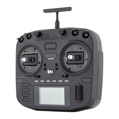
RadioMaster MT12 User manual

MT12
Instrucon manual
Version:1.0
WWW.RADIOMASTERRC.COM
This manual is adapted from the EdgeTX online manual, which is provided and maintained by the EdgeTX team under
the Creave Commons Aribuon-ShareAlike 4.0 Internaonal (CC BY-SA 4.0) license. Full credit is given to the EdgeTX
team and contributors. More details can be found here: EdgeTX Online manual

Contents
1. Overview .......................................................................................................................................................................4
1.1. Introducon ...........................................................................................................................................................4
1.2. Safety informaon..................................................................................................................................................4
1.3. Radio overview.......................................................................................................................................................5
1.4. Baery and charging informaon..........................................................................................................................6
1.5. Manual and rmware download............................................................................................................................6
1.6. Specicaons .........................................................................................................................................................6
1.7. Warranty and repair...............................................................................................................................................7
1.8. Disclaimer & Legal status and copyright................................................................................................................7
1.9. Quick Start How-to videos .....................................................................................................................................8
2. User Interface................................................................................................................................................................8
2.1. Buon layout..........................................................................................................................................................8
2.2. Main View ..............................................................................................................................................................9
2.3 Reset......................................................................................................................................................................10
2.4. Stascs ...............................................................................................................................................................10
2.5. Custom RGB LED Setup ........................................................................................................................................12
2.6. Switch and Joysck Expansion Modules ..............................................................................................................13
3. Model Sengs ............................................................................................................................................................14
3.1. Model Select ........................................................................................................................................................14
3.2. Setup ....................................................................................................................................................................14
3.2. Drive Modes.........................................................................................................................................................21
3.3. Seng Fail Safe ....................................................................................................................................................24
3.4. Reversing a Servo.................................................................................................................................................25
3.5. Seng EXPO.........................................................................................................................................................25
3.6. Seng Dual Rate..................................................................................................................................................25
3.7. Seng End points ................................................................................................................................................26
Inputs, Mixes & Outputs .................................................................................................................................................27
3.5. Inputs ...................................................................................................................................................................27
3.6. Input conguraon page......................................................................................................................................28
3.7. Mixes....................................................................................................................................................................30
3.8. Outputs ................................................................................................................................................................31
4. Curves..........................................................................................................................................................................32
5.1 Seng curves........................................................................................................................................................32
5. Logical Switches ..........................................................................................................................................................33
6.1. Using Logical Switches..........................................................................................................................................33
6. Special Funcons.........................................................................................................................................................34
7.1. Conguring Special Funcons..............................................................................................................................34
7. Telemetry ....................................................................................................................................................................37

7.1. Sensors.................................................................................................................................................................37
8.2. Sensor Conguraon............................................................................................................................................38
8.3. Common Telemetry Sensors ................................................................................................................................40
8. Display.........................................................................................................................................................................41
8.1. Display screen conguraon................................................................................................................................41
9. Radio Sengs..............................................................................................................................................................43
10.1. Tools ...................................................................................................................................................................43
10.2. Radio Setup........................................................................................................................................................43
10.3. Global Funcons ................................................................................................................................................45
10.4. Trainer ................................................................................................................................................................45
10.5. Hardware............................................................................................................................................................46
10.6. Version ...............................................................................................................................................................48
10. Contributors and Further informaon......................................................................................................................48
11.1 Special thanks......................................................................................................................................................49
11.2 Links and resources.............................................................................................................................................49

1. Overview
1.1. Introducon
Thank you for purchasing the RadioMaster MT12 radio system. Advanced and highly-versale, MT12 is adaptable for
drivers of any skill level. To ensure safe and reliable operaons, please read this manual carefully prior to use.
As the soware and hardware are constantly improved, the informaon contained in this manual is subject to change
without prior noce. Please visit our website for up-to-date informaon and radio rmware.
MT12 is an open-sourced, ergonomic radio with powerful mul-protocol capability. Able to bind to most
contemporary protocols on the market, this is one radio to rule them all! MT12 runs EdgeTX, an open-sourced
operang system; for more informaon, please visit the EdgeTX link below.
-The RadioMaster team
1.2. Safety informaon
Radio-controlled models commonly contain sharp components like gears, rotang at high RPMs; when operang or
maintaining the model, always use common sense and proceed with cauon.
Always disconnect power to the model during the assembly or maintenance process.
Never operate the MT12 radio system in the following condions:
• In severe weather or strong windy condions, such as rain, hail, snow, storms or electromagnec environments.
• In limited visibility
• In the proximity of other people, property, high-voltage power lines, public roads, vehicles or animals
• When feeling unwell, or under the inuence of drugs or alcohol.
• If the MT12 radio system/model is damaged or showing signs of interference.
• In areas with high 2.4GHz interference or where 2.4GHz radios are prohibited.
• When the Transmier or receiver baery is low.
• In areas where local regulaons prohibit the use of R/C models.
WARNING!
MT12 is pre-installed with the most stable rmware at the factory at me of release. please only aempt to update
the rmware if you are condent in the process. Incorrect rmware updates may cause the remote control to
become inoperable. Damage as a result of improper rmware update may not be covered under warranty.

1.3. Radio overview

1.4. Baery and charging informaon
MT12 is powered by 2x 3.7V 18350 Lithium Ion cells and is charged using the built-in USB-C port. The charging
circuitry is designed for charging 2x 3.7V Lithium Ion/Poly or 1x 7.4V Lipo baery pack only; the nominal voltage is
3.7V and the maximum charging voltage is 4.2V.
Never charge 3.6V LiFe and 3.6V 18350 Lithium Ion packs with the onboard charger. Charging or using the wrong
baery chemistry/polarity may cause permanent damage to the PCB and in certain situaons cause res.
Check the voltage and condion of the baery regularly and never charge the device unaended. Only charge in safe
areas away from combusble materials. Refrain from charging the radio unit if it was exposed to water or was
damaged in any way. RadioMaster does not assume any responsibility for any adverse consequences caused by the
use or misuse of this product.
1.5. Manual and rmware download
MT12 is pre-installed with factory approved EdgeTX rmware and is also capable of operang OpenTX. To download
the latest manual or stock factory rmware, please visit the RadioMaster website: hps://www.radiomasterrc.com
When updang your radios rmware we would encourage you to use EdgeTX Buddy.
EdgeTX
hp://edgetx.org/ (Informaon about EdgeTX)
hps://buddy.edgetx.org/ (easy to use tool for FW updates)
hps://edgetx.gitbook.io/edgetx-user-manual/ (EdgeTX Online manual)
ExpressLRS
hps://www.expresslrs.org/quick-start/geng-started/ (ExpressLRS Online guide)
Mul-Module
hps://www.mul-module.org/ (Online resources)
1.6. Specicaons
Physical dimensions:177.8*118.4*207.8mm
Weight:480 grams
Operang frequency:2.400GHz-2.480GHz
Internal RF Opons:4-in-1 mul-protocol / ELRS 2.4GHz
Supported protocols :Module dependent
Operaonal current: 160mA for 4 in 1. 400mA for ELRS 250mW .
Operaonal voltage:6.6-8.4V DC
Operang system:EdgeTX
Control channels:Maximum 16 (Rx dependent)
Display :128*64 Monochrome LCD
Baery :2 x 18650 cells or a 2s 7.4v 5000mah baery pack (Baeries not included)
Charging :Built in USB-C Charging
Firmware Upgrade method:Via USB or SD card
Gimbal:Hall-eect
Module bay :Nano size (RadioMaster Ranger Nano Module / RadioMaster RM 4in1 module /
TBS Crossre Nano module)

1.7. Warranty and repair
Should any issues arise with your radio system's hardware, please keep the proof of purchase and contact the retailer
where you made the MT12 purchase. . You may also visit our warranty support page
hps://www.radiomasterrc.com/contact
The limited warranty covers defects in workmanship for one year from the date of purchase
1.8. Disclaimer & Legal status and copyright
EdgeTX is open source rmware. No warranty or implied warranty is given for the quality and reliability of this
rmware. If not handled properly, the RC model can cause serious injury or even death. If you decide to use EdgeTX
rmware, you are solely responsible for your model. EdgeTX and RadioMaster are not liable for any injury or damage
caused by using EdgeTX rmware or RadioMaster hardware. Use with cauon.
This project is free soware: you can redistribute and / or modify it in accordance
with the GNU General Public License Agreement, V3 version agreement, or (oponally)
an updated version agreement issued by the Internaonal Free Soware Associaon. You should receive a copy of
the GNU General Public License Agreement for the EdgeTX project. If not, see www.gnu.org/licenses. EdgeTXis open
sourced rmware for RC radio controllers. The rmware is highly congurable and has more features than tradional
radios. Daily feedback from thousands of users ensures connuous rmware updates as well as stability andquality.
The release of EdgeTX rmware hopes that it will benet the public, but it has no warranty; it does not include
implied commercial licenses or applicability for a special purpose. For more details, see the GNU General Public
License Agreement. EdgeTXsource les and more can be found at hps://github.com/opentx/opentx and
hps://github.com/edgetx/edgetx.

1.9. How to BIND videos
How to bind an R85C Receiver with a 4in1 MT12
How to bind an ER3C-I receiver with ExpressLRS MT12
2. User Interface
2.1. Buon layout
•[SYS] - System Button - Short
press [SYS] button from the
main screen to go to the tools
page of the Radio Settings
menu.
•[MDL] - Model Button - Short
press [MDL] button from the
main screen to go to the
Model Select of the Models
menu
•[RTN] - Return / Back - Short
press [RTN] button to return
to the previous page,
previous menu or cancel
action
•[PAGE>] / [PAGE<] - Page
next & page previous - Used
to navigate between different
screens, tabs, or options
settings, depending on the screen.
•[TELE] - Telemetry - Press the [TELE] button to go to the configured telemetry screens. More
information about the telemetry screens is found in the Display section.
•[Roller] or [Dial] - Next & previous value The roller is used to navigate through menu options.
•[Enter] - Accept - Used to select option, function or accept value - Push [Roller] button to select or
enter.

2.2. Main View
Screen 1 - This view displays the model name, trim positions (if trims are
enabled), clock, transmitter battery voltage, Drive mode, receiver signal
strength, and Timers 1 and 2 (if enabled).
Screen 2 - This view displays the model name, trim positions (if trims are
enabled), clock, transmitter battery voltage, Drive mode, receiver signal
strength, and Timer 1 (if enabled). It also has a graphical representation
of the stick, pot, and switch positions.
Screen 3 - This view displays the model name, trim positions (if trims are
enabled), clock, transmitter battery voltage, Drive mode, receiver signal
strength, and Timer 1 (if enabled). It also shows the numerical values of
the output channels, 8 channels per page. Use the [Roller] to scroll thru
the additional pages.
Screen 4 - This view displays the model name, trim positions (if trims are
enabled), clock, transmitter battery voltage, Drive mode, receiver signal
strength, and Timer 1 (if enabled). It also shows the values of output
channels as a bar graph, 8 channels per page. Use the [Roller] to scroll
thru the additional pages.
Screen 5 - This view shows either the channel monitor or mixer monitor,
8 channels per page. Use the roller or dial to scroll thru the additional
pages. Push the [Roller] button to switch between the channel monitor
and mixer monitor.
Long pressing the [Roller] button from the main view screen will show a
pop-up menu with the options below:
•View Notes - Displays the congured model checklist. This opon is only visible if a valid model checklist le
is in the Models folder.
•Reset - See Reset page.
•Stascs - See Stascs page.
•About - Displays the EdgeTX rmware version being used by the radio.

2.3 Reset
Selecng Reset from the pop-up menu will give you the following opons:
Reset ight - When selected, this opon:
•Resets all mers congured with a persistence seng of Flight to zero.
•Resets all discovered telemetry sensor values.
•Resets all logical switch states
•Triggers the same checks as loading the model - i.e. throle posion, switch state, is failsafe set check,
display pre-ight checklist if congured, stuck keys test, etc.
Reset mer 1 / 2 / 3 - Resets only the selected mer to zero regardless of the congured persistence seng.
Reset telemetry - This opon resets all discovered telemetry sensor values
2.4. Stascs
The Stascs screen presents you with stascs regarding radio usage. All data is reset once the radio is powered o.
The following informaon is provided:
•SES - The amount of me that the radio has been turned on.
•THR - The amount of me that the throle has was above the 0% sck posion.
•TH% - The amount of me that the throle has was above the 50% sck posion.
•TM1/2/3 - The current values of Timer 1, Timer 2, and Timer 3.
•Throle Graph - Shows the throle percentage over me.
Long pressing the [Roller] or [Dial] buon will reset the Stascs and Debug screens.
Pressing [PAGE>] will take you to the Debug screens.
Debug screen 1

The Debug screen provides data points used by the developers when debugging issues in the soware. Most users
will not nd the informaon useful on this screen unless debugging issues with developers. The following debug
informaon is provided.
•Free mem - Current free radio memory in bytes.
•Lua scripts
o[D] - Maximum Lua duraon in milliseconds.
o[I] - Maximum Lua interval in milliseconds.
•TMix max - Maximum mixer task duraon.
•Free stack - [Menu] / [Mix] /[Audio]
o[Menu] - Minimum free stack memory for menu tasks.
o[Mix] - Minimum free stack memory for mixer tasks.
o[Audio] - Minimum free stack memory for audio tasks.
•Tlm RX Err - Numer of received telemetry errors

2.5. Custom RGB LED Setup
The MT12 features RGB LEDs that are user programable via LUA scripts. A basic set of LUA scripts are included with
the radio. You will be able to program any sequences of lights and aects you choose with a LUA script and can share
your scripts with other users.
The LUA scripts for RBG eects are in the “\SCRIPTS\RGBLED” folder of the MT12 SD card.
To choose a colour or eect for your MT12 you can use one of the included LUA scripts, create your own LUA script or
download a community made script and place it in the folder above.
To set one universal colour/eect turn on the RGB leds funcon in GLOBAL FUNCTIONS and choose a script.
To set a colour/eect for each dierent model turn on the RGB leds funcon in SPECIAL FUNCTIONS and choose a
script.
Advanced uses for RGB LEDS
Other than looking cool the RGB LEDs have some praccal applicaons too! A combinaon of Logical Switches and
special funcons can be used to add extra funconality to the RGB lighng system.
For example, the RGB light colour can be linked to telemetry data from the baery of the model. A voltage threshold
could be set to change the RGB colour from GREEN to RED when the baery reaches a specied voltage and the
“POLICE” eect (ashing blue and red) when the model has not been powered up yet or Telemetry is lost.
First create these logical switches:
Then setup these special funcons.
The possibilies are endless and can be customised to suit your needs.

2.6. Switch and Joysck Expansion Modules
The MT12 features interchangeable expansion modules and includes a two 2 posions switch module and a 4 way
Joysck module. You can choose the module you wish to install based on your own preferences.
Hardware Installaon
Two 2 Posion switch module:
4 way Joysck module:
Soware Setup
Two 2 Posion Switch module:
For the two 2 Posion switch plate, press the SYS buon and then Page > buon to reach the HARDWARE page.
Using the roller scroll down to S3 and S4. Set both S3 and S4 to “Switch”. Next, scroll down to FL1 and FL2. Set FL1 to
S3 and choose “2POS”. Set FL2 to S4 and choose “2POS”.
4 Way Joysck module:
For the 4 way Joysck plate, press the SYS buon and then Page > buon to reach the HARDWARE page. Using the
roller scroll down to S3 and S4. Set S3 to Axis X and set S4 to Axis Y. Once this is set, please enter the calibraons
screen and do a calibraon (as you would for the wheel, trigger and knobs). Please note, at the me of wring this
manual there is no visual display of the 4 way joy sck movement when calibrang, however the calibraons is taking
please. Please move the 4 way joysck across both axis and complete the calibraon.

3. Model Sengs
3.1. Model Select
Pressing the [MDL] buon from the Main view will open the Model Select screen.
Use the [Roller] or [Dial] to scroll through the model slots.
Pressing [Enter] on an empty model slot will give you the following opons:
•Create Model - This opon creates a new model with the default conguraon opons.
•Restore Model - This opon creates a new copy of a selected model that has been previously backed up.
Pressing [Enter] on an occupied model slot that is not the acve model (not marked with an asterix *) will
give you the following opons:
•Select Model - this opon selects this model as the acve model.
•Backup Model - This opon makes a copy of the model in the Backup folder on the SD Card.
•Copy Model - This opon makes an exact copy of the model and allows you to select which model slot it will
be placed in.
•Move Model - This opon allows you to move the selected model to a dierent model slot.
•Delete Model - This opon deletes the selected model.
Pressing [Enter] on an occupied model slot that is the acve model (marked with an asterix *) will give you
the following opons:
•Move Model - This opon allows you to move the selected model to a dierent model slot.
•Copy Model - This opon makes an exact copy of the model and allows you to select which model slot it will
be placed in.
•Backup Model - This opon makes a copy of the model in the Backup folder on the SD Card.
3.2. Setup
The Setup screen is where you start to congure your model. It contains the following sengs:
Name - Name of the model. The maximum number of characters is 10.

•To edit the text, using the [roller] or [dial], press the buon, scroll to select the desired leer, then press the
buon again to move to the next space. To toggle between lower and upper case, long-press the buon.
Press the [RTN] buon to exit out of text eding mode.
Image - Image displayed on the main view (only for radios with 212 x 64 displays).
Image dimensions shall be 64 x 32 pixels, 16 bit, grayscale, .bmp le. The image must be stored in the IMAGES folder
of the SD card.
Timers
Timer 1/2/3 - There are 3 congurable mers in EdgeTX. The following conguraon opons will be displayed once
the mer is no longer set to OFF:
Timer 1 [Mode] [Switch]
[Mode]: The opons include:
•OFF- The mer is not used
•ON - The mer runs all the me
•Strt (Start) -The mer starts once the congured switch is acvated. Aer the me is started, the mer
ignores the switch posion.
•THs (Throle) - The mer starts once the throle is raised and the congured switch is acvated. The mer
will stop counng if either the throle posion is lowered back to the minimum value or the congured
switch is deacvated.
•TH% (Throle %) - The mer counts proporonally to the throle. It counts in real-me at full throle and
half speed at 50% throle.
•THt (Throle Start) - The mer starts once the throle is raised and the congured switch is acvated. Aer
starng, the mer ignores the throle posion and will keep counng unless the switch is deacvated.
[Switch]- Select the switch that will trigger the mer to start. If no switch is selected, the mer will trigger based only
on the congured mode. In addion to a switch, you can also select a trim, a telemetry source (triggered when
telemetry data is received from that source), or physical acvity (sck movement or buon press) (labelled as ACT)
Those items with a "!" mark in front of the trigger name mean that the condion is reversed. For example, "!SA-"
means "when SA switch is not in middle/centre posion (= up or down)".
Name: Name of the mer
Start- The me used for the mer's advanced funcons. The default value is 00:00 and when le as such, the mer
operates like a stopwatch, counng upward unl stopped. If a dierent me is entered in this box, then the
addional eld will appear next to the me with the opons: Remain or Elaps.
If set to Remain, the counter will funcon like a countdown mer - counng down from the designated me to zero
and then alerng the user. If set to Elaps, the mer funcons like an alarm, counng up from zero unl the
designated me and then alerng the user.
Persist (Persistence):
•O - The mer value is reset when switching models or when the radio is turned o / on.
•Flight - The mer value is NOT reset when switching models or when the radio is turned o / on. The mer
value is only reset when the Reset ight opon is selected in the Reset menu.
•Manual Reset - The mer value is reset only when it is individually selected to be reset (example: Reset
mer1) in the Reset menu.

Minute (Minute Call) - If selected, you will be noed every minute that passes as described in the Count Down
opon.
Count Down:
•Silent - No nocaon is given unl the mer reaches zero. When it reaches zero, you will hear one beep.
•Beeps - The radio will beep every second starng at the me designated.
•Voice - The radio will count down by second starng at the me designated.
•Hapc -The radio will vibrate every second starng at the me designated.
Trims sengs
Trims
E.Limits (Extended Limits) - When enabled, it increases the minimum and maximum range for the output values to -
150 and 150. Extended limits are necessary if the full range of the control surface cannot be reached with standard
limits.
E. Trims) Extended Trims: Increases the maximum trim adjustment value from ±25% to ±100%.
Reset - This resets all trim values to zero.
Show trims: When set to Yes, it will display the numerical trim value on the trim bar. When set to CHANGE, it will
display the numerical value once the trim is no longer at zero.
Trim Step: Denes the amount of increase/decrease in trim when the trim switch is pressed.
•Course = 1.6%
•Medium = 0.8%
•Fine = 0.4%
•Extra Fine = 0.2%
•Exponenal = 0.2% near the centre and the step value increases exponenally as the distance from the
centre increases.
Throle Sengs
Throle
The throle related conguraon opons below are displayed in collapsible menu.
T-Reverse: When enabled, this opon reverses the output direcon of the congured throle channel.

T-Source: The source that will be used for the throle.
T-Trim-Idle: When enabled, the throle trim will only aect the boom poron of the throle band.
For example, with Trim idle only enabled, the throle sck at the lowest point might have a value of -80 and the
center point will sll be 0 and the highest point of 100. Without this enabled, the throle sck at the lowest point
might have a value of -80 however, the center point will be 20 and the highest point of 100.
T-Trim-SW: The trim switch that will be used to trim the throle. It is possible to substute the throle trim switch
with the aileron, rudder, or elevator trim switches.
Preight Checks opons
Preight Checks
Whenever a new model is loaded, EdgeTX will conduct pre-ight checks based on the checks that are congured on
this page. If any of the checks are failed, EdgeTX will give the user an audio and visual warning that must be
acknowledged before using the model. The following preight checks below are displayed in collapsible menu.
Checklist - When this opon is selected, the model notes le will be displayed when the model is loaded. A valid
model notes le must be in the Models folder on the SD card. The model notes le must be a .txt le and must have
the EXACT same name as the model it is for, for example: Mobula6.txt. The text in the le is up to the user.
T-Warning - When selected, the radio will check that the throle is at the minimum value for the congured throle
source in the T-Source conguraon opon.
Cust-Pos - When this opon is selected, the value designated in POS.% will be used for the T.Warning.
Pos.% - minimum value of the throle for the throle warning when Cust-Pos is enabled.
S-Warning - The secon displays all the switches that are congured on the radio and allows you to select which
posion is the correct posion for the switch state check. Selecng the switch will cycle through the available switch
posions or turn the check o for the switch completely.
Pot warn- When acvated, this opon checks the posion of the pots & sliders. There are three opons - OFF, ON
and AUTO. When ON or AUTO is selected, buons for the available pots and sliders will appear. To enable the Pot
warning for an individual Pot, select the pot with the [roller] or [dial] and click the buon to highlight it. Highlighted
pots are enabled.
•OFF - Pot and slider posions are not checked.
•Manual - Posions are checked against manually congured pot and slider posions. To manually set the
check posion, select manual the from menu, select the item that you want to set, and long-press the
[Enter] buon to set its current posion for the check.
•AUTO - Posions are checked for pots and sliders and compared to the last automacally saved posion
before the radio was turned o or the model was changed.
Ctr Beep - Allows you to turn on/o the centre beep funcon for the individual scks, pots, and sliders by
highlighng them with the [roller] or [dial] and pressing the buon. When a switch is highlighted, the funcon is
enabled.

Glob. Funs - When enabled, global funcons programmed in the radio sengs will apply to this model. When
disabled, global funcons will not apply to this model.
ADC Filter - Enables/disables the ADC lter for this model. The global opon will take the value designated in the
radio sengs, which is on by default.
The ADC lter is a lter for the proporonal channels (scks, pots, sliders), smoothing out smaller fast movements
that occur due to noise in the system electronics. Normally, this lter should be disabled for models with ight
controllers.
Internal / External RF
The conguraon sengs for both the Internal and External RF secons work the same. The only dierence is that
the Internal RF secon is for conguring the built-in module and the External RF secon is for conguring an RF
module in the external module bay.
The conguraon opons are: o or the module name of the installed module as congured in the Radio sengs.
Conguraon opons are unique to each installed module. Please consult the manufacturer's documentaon for
conguraon opons.
Conguraon opons for the mul-protocol module are described here: hps://www.mul-module.org/using-the-
module/protocol-opons
Receiver number - A receiver number is a user-assigned number for a model that is sent to the receiver when bound.
Each model must have a unique receiver number. However, models using dierent protocols may have the same
receiver number without issues. EdgeTX will inform you when a receiver number is unique or if it is already being
used with a text above the number eld.
If using the radio in gamepad mode, both internal and external RF modules should be turned o. This will result in
increased performance when connected to a computer via USB.
Trainer
Trainer Mode - The Trainer Mode opon is where you can congure the CPPM passthrough mode and method.
When enabled, this allows the CPPM signals from a radio in Slave mode to be passed through to another radio in
Master mode which will then pass the signal to the model it is connected to. CPPM passthrough can be used for
several dierent use cases, such as: connecng a head tracker, Instructor / Student training mode, and controlling
complex models that require more sck inputs than available on a standard transmier.
Master mode - This is the mode for the radio that will be connected to the model. This radio also shall congure the
special/global funcon (Trainer) to acvate the passthrough mode. When the passthrough mode is acvated, the
CPPM signals from the radio in Slave mode will be sent to the model for control.
Slave mode - This is the mode for the radio that will pass it's CPPM values to the radio in Master mode, which are
then sent to the model.
Below are the possible conguraon opons:
•O - Trainer mode is not used for this model.
•Master / Jack - Master mode using a cable connecon.
•Slave / Jack - Slave mode using a cable connecon.
oChannel Range - This is the range of channels that will be sent to the radio in Master mode. Channel
10 is the recommended last channel to use.
oPPM Frame - The rst eld is the length of the PPM frame. The second eld is the stop length/delay
between pulses. The dropdown is to select the polarity of the signal. The frame length is
automacally adjusted to the correct value when the number of transmied channels is changed.

However, this automacally assigned value can be manual changed. Note: In most cases, the default
seng does not need to be changed.
•Master / Bluetooth - Master mode using a Bluetooth connecon (if installed in radio).
•Slave / Bluetooth - Slave mode using a Bluetooth connecon (if installed in radio).
•Master / Mul - Master mode using an addional externally mounted Mul-protocol module for the
connecon. For more informaon on this setup, see Set-up wireless trainer with a Mul -protocol module
Enabled Features opons
Enabled Features
The Enabled Features secon allows you to congure which pages are visible in the selected model's radio setup and
model sengs area of EdgeTX. The page names are displayed in a collapsible menu with the following congurable
opons:
•Global - When selected, the tab will take the global value congured in the Enabled Features area in Radio
Setup. The congured global value will display next to the opon.
•On - When selected, this tab will be visible when this model is loaded.
•O - When selected, this tab will not be visible when this model is loaded.
Note: Turning o a tab only hides the tab and does not change the items already congured in that tab. For example,
if you congure a special funcon and then turn o the special funcons tab, the special funcon will sll work as
congured.
EXCEPTION: Turning o the Global Funcons tab will disable congured global funcons for that model.
USB Joysck advanced mode sengs
USB Joysck
The USB Joysck has two possible modes, Classic and Advanced.
In Classic mode, the radio's congured output channels will be sent to the target device in numerical order and
mapped to the device's precongured USB controller axes and buons. Below is the default channel mapping for
Microso Windows.
•Ch1 - X Axis
•Ch 2 - Y Axis

•Ch 3 - Z Axis
•Ch4 - X Rotaon
•Ch 5 - Y Rotaon
•Ch 6 - Z Rotaon
•Ch 7 - Dial
•Ch 8 - Slider
•CH 9 - Ch 32 - Buons 1 - 24
In Advanced mode you can congure the following addional opons:
If mode (Interface mode): This indicates to the target device (the device you are connecng your transmier to)
what type of device you are connecng. The opons are Joysck, Gamepad, MulAxis.
Note: Currently there is a limitaon in MS Windows that may limit your transmier to being only detected only as a
Joysck, regardless of what is selected in this opon. In MacOS, Linux and Andriod this funcons properly.
Circular cutout: For axis pairs (X-Y, Z-rX): By default, the range of the axis pairs is a rectangular area. With this opon,
the axis will be limited to a circular area (like gamepad controllers commonly are). Opons are : None or X-Y, Z-rX or
X-Y, Rx-Ry
Channel Sengs
Mode: For each output channel, you can select the mode that you want to use for that channel. The available
opons are None, Btn, Axis, Sim.
None - Channel is not used
Buon mode opons for a selected channel
Btn - Channel is used to simulate a buon. Conguraon opons include:
•Inversion - Inverts the output channel signal. Opons are: On / O
•Buon Mode -
oNormal - Each posion of a mulposion switch is represented by a buon. The current switch state
is represented by a connuous buon press.
oPulse - Similar to "Normal" mode. However, instead of connuous buon press it is represented by a
short buon press.
oSWEmu - The toggle switch emulaons a push buon. The rst press turns the virtual buon on, the
second press turns it o.
oDelta - The change of the output channel is represented by 2 buons. While the output value is
decreasing, the rst buon is pressed. When the output value is increasing, the second buon is
pressed. If there is no change, then no buons will be pressed.
oCompanion - This opon should be selected when using your transmier to control the simulator in
EdgeTX Companion. It allows the mul-posion switches to funcon properly in the simulator.
Other manuals for MT12
1
Table of contents
Other RadioMaster Controllers manuals
Popular Controllers manuals by other brands

Energy Master
Energy Master HHPM SERIES Installation, Operation, Maintenance, Service Manuals

SIGMAKOKI
SIGMAKOKI OptoSigma PGC-04-U manual

Coelbo
Coelbo OPTIMATIC 22 instruction manual

Val Controls
Val Controls IHP24 Troubleshooting

GO Regulator
GO Regulator HPR-2 Wiring instructions

Geco
Geco GC202 Installation, operating and maintenance manual