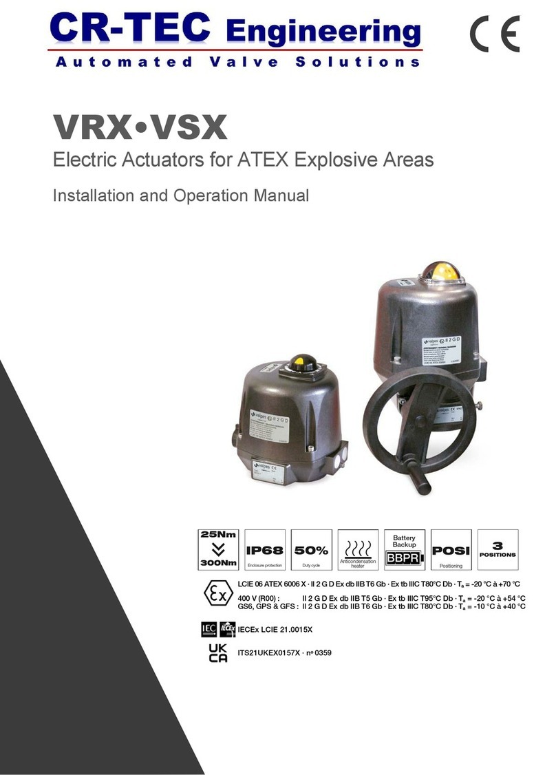
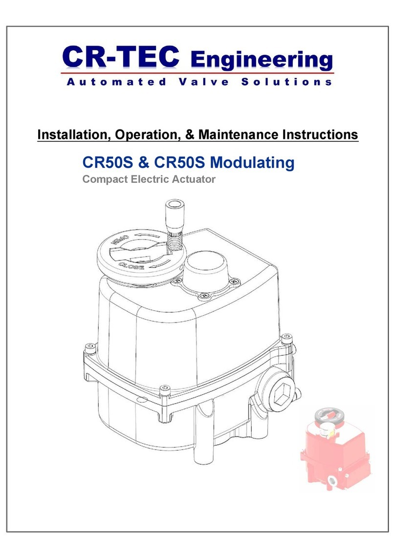
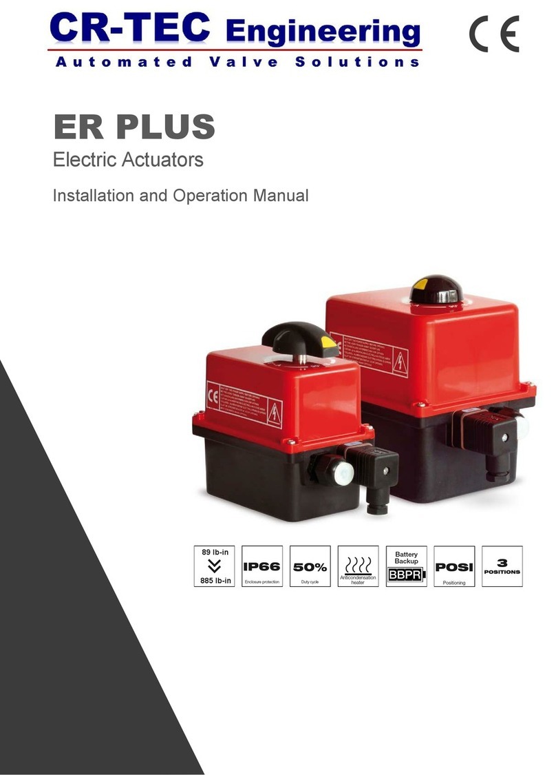
CR-Tec ER PREMIER ER20 User manual

20Nm
30%
Duty cycle
IP65
Enclosure protection
ER PREMIER
Electric Actuators
Installation and Operation Manual

1
Index
General information.......................................................................................................
Description
Transport and storage
Maintenance
Safety instructions
Position indicator...........................................................................................................
Emergency manual override..........................................................................................
Dimensions ....................................................................................................................
Electric wiring ................................................................................................................
Warnings
Wiring Instructions
Electric diagram
Electronic boards
Technical data................................................................................................................
This product meets the European Directive 2012/19/UE about electrical and electronic equipment (DEEE). It mustn't
be mixed with common waste. Please, recycle or dispose of them according to your country laws.
2
3
3
4
5
9
CR-TEC Engineering Inc. • [email protected] • www.crtec.com • 203-318-9500

2
DESCRIPTION
These electric actuators have been designed to perform the control of a valve with 90° rotation. Please consult us for any different appli-
cation. We cannot be held responsible if the mentioned actuators are used in contradiction to this advice..
TRANSPORT AND STORAGE
The forwarding agents being held as responsible for damages and delays of the delivered goods, the consignees are obliged to ex-
press if applicable their reserves, prior to accept the goods. The goods delivered directly ex works are subject to the same conditions.
The transport to the place of destination is carried out by using rigid packing material.
The products must be stored in clean, dry, and ventilated places preferably on appropriate palettes or shelves.
MAINTENANCE
Maintenance is ensured by our factory. If the supplied unit does not work, please check the wiring according to the electric diagram as
well as the power supply of the concerned electric actuator.
For any question, please contact our after-sales service.
To clean the outside of the actuator, use a lint and soapy water. DO NOT USE CLEANING PRODUCT WITH SOLVENT OR ALCOHOL
SAFETY INSTRUCTIONS To be read prior to the installation of the product
The electric power supply must be switched-off before any intervention on the electric actuator (i.e. prior demounting its cover or ma-
nipulating the manual override knob).
Any intervention must only be carried out by a qualified electrician or other person instructed in accordance with the regulations of
electric engineering, safety, and all other applicable directives.
Strictly observe the wiring and set-up instructions as described in the manual: otherwise, the proper working of the actuator can not be
guaranteed anymore. Verify that the indications given on the identification label of the actuator fully correspond to the characteristics of
the electric supply.
Do not mount the actuator « upside down ». Risks:
Declutching mechanism failure
Possible flow of the grease on the electronic board
Do not mount the actuator less than 30 cm of a electromagnetic disturbances source.
Do not position the equipment so that it is difficult to operate the disconnecting device.
CR-TEC Engineering Inc. • [email protected] • www.crtec.com • 203-318-9500

3
Position indicator
Handle with position indicator for ER20 and round
indicator for ER 35/60/100
Modular position indicator with three removable position markers (3 yellow +
2 black), adjustable according the type of valve to be actuated
Valve 0° 180°
2-way:
0° = close
90° = open
3-way (L):
3-way (T):
Ex: T1
90°
Emergency manual override
The priority functioning mode of this actuator is electric. Be sure than the power supply is switched off before using the manual
override
1. Turn the knob to position MAN (counter-clockwise) and hold it in position.
2. Turn the outgoing drive shaft of the actuator with the help of an adjusting spanner.
3. In order to re-engage the reduction, release the knob (spring return).
1 2 3
CR-TEC Engineering Inc. • [email protected] • www.crtec.com • 203-318-9500

4
Dimensions
Visual position indicator
Nylon
PA6
cover
F03/F05-F04 plate
Ou / Or
Sleeve
9
Nylon GF
PA6 Housing
Clutch
knob 11
Square / Star (mm) Depth (mm)
14 16
17 19
22 24
ISO F flange Diameter (mm)
F03 36
F04 42
F07 70
M threaded Depth (mm)
M5 14.2
M5 14.2
M8 16.4
Screws quantity
4
4
4
F05 50 M6 14.2 / 16.4 4
ER20
Star 14 (mm)
ER35/60/100
Star 22 (mm)
Handle for manual override
CR-TEC Engineering Inc. • [email protected] • www.crtec.com • 203-318-9500

5CR-TEC Engineering Inc. • [email protected] • www.crtec.com • 203-318-9500
Electric wiring
As stipulated in the applicable regulation, the connection to earth contact is compulsory for devices with working voltages exceeding 42V.
The actuator is always powered, so it must be connected to a disconnection system (switch, circuit breaker) to ensure the actuator power
cut, correctly located, easily reached and marked as being the disconnecting device for the equipment.
An Inrush current may occur when actuators are switched on. Therefore it is necessary to limit the number of actuators on the same line.
Alternatively an inrush current limiter at the output of the circuit breaker may be used.
The terminal temperature can reach 90°C
For a use with a long power supply wiring, the induction current generated by the wires mustn't be higher than 1mA
In order to ensure the IP65 tightness, the cable gland for feedback wiring must be used (7 to 12mm cable). Otherwise, the cable
gland must be replaced by a ISO M20 IP65 cap.
Protective
earthing
Ground Direct voltage Alternating voltage
Dangerous
voltage
Warnings
Instructions
Our cable glands are designed for cables with a diameter between 7mm and 12mm.
The actuator can support MAINS supply voltage fluctuations up to ±10 % of the nominal voltage.
It is necessary to connect all actuators to an electrical cabinet
Remove the position indicator, unscrew the four screws and take off the cover.
SUPPLY AND CONTROL WIRING
Ensure that the voltage indicated on the actuator ID label corresponds to the voltage supply.
Connect the wires to the connector in accordance with the required control mode. (see diagram p.15)
WIRING OF THE FEEDBACK SIGNAL
Our actuators are equipped with two simple limit switch contacts normally set either in open position, either in closed position (see wir-
ing diagram DSBA0436). As per factory setting, the white cam is used to detect the open position (FC1) and the black cam is used to
detect the closed position (FC2).
The auxiliary limit switches must be connect with rigid wires. If the applied voltage is higher than 42V, the user must foresee a
fuse in the power supply line.
The voltages applied to each feedback switch (FC1 and FC2, SNAA690000 electronic board) must be exactly the same .The
reinforced insulation between the feedback signal and the motor control authorizes voltages up to 250V AC.
Unscrew the right cable gland and insert the cable.
Remove 25mm of the cable sheath and strip each wire by 8mm.
Connect the wires to the terminal strip in accordance with the diagram p.15
Tighten the cable gland (Ensure that it’s well mounted to guaranty the proofness).
Connection to feedback microswitches:
4 to 24 V DC and 12 to 250 V AC
minimum current 100 mA
maximum current 5 A (resistive), 0.5 A (motor), 0.125 A (capacitive loads)
SETTING OF END LIMIT SWITCHES
The actuator is pre-set in our factory. Do not touch the two lower cams in order to avoid any malfunctioning or even damage to the
actuator.
To adjust the position of the auxiliary contacts, make rotate the two superior cams by using the appropriate wrench.
Re-mount the cover, fasten the four screws and attach the position indicator.

Wiring the electrical connector:
1. Remove the connector screw first, and then use a flat screwdriver to pry apart the two
connector halves. Note that the screw placed in the connector locks the two halves
together.
2. The center terminal is an optional ground that is normally used with AC current, and not
normally used with DC current.
3. When used with a solenoid valve, the polarity for the power con-nections is not
important. The two power wires can each be con-nected to either of the side terminals.
With electric motor actua-tors, the polarity should be observed for both AC and DC
opera-tion.
4. Place the connector on the electric motor actuator or solenoid valve coil and hold in
place with the supplied screw.
5. There are two different types of connectors that you may be using, ½” NPT Conduit and
Lead Wire. If you are using the Lead Wire type, a jacketed multi-conductor wire is
recommended. A rubber grommet is compressed around the jacketed conductor to
make a seal. If a tight seal is not important, then any type of wiring can be used.
ELECTRIC WIRING
INSTRUCTIONS - DIN Electrical Connector
6
CR-TEC Engineering Inc. • [email protected] • www.crtec.com • 203-318-9500

SNAA690000
FCF
FC0
A
+
— ~
~
FC2
FC1
A
321
24V 50/60Hz (24V DC)
100V-240V 50/60Hz (100V-350V DC)
C
B
M
GND 987654
2
3
1
COMMON FC1/FC2 FEEDBACK FC1FEEDBACK FC2
1
2 3
ECD.1A
Grey connector
987654
1
2 3
SUGGESTED CUSTOMER WIRING
N
-
Open Close
Ph
+
N
-
Open
Ph
+
GND GND
2
3
1 2
3
1
POWER SUPPLY : 3P+T DIN43650 CONNECTOR
IF CONNECTOR OPTION (ECD.1A)
IF WIRING TROUGH THE CABLE GLAND
7CR-TEC Engineering Inc. • [email protected] • www.crtec.com • 203-318-9500
3-Position Switch Control On-Off Switch Control
POSITION OUTPUT SWITCHES
Switch Description
•Terminal temperature maximum 194°F / 90 °C
•Use solid wires, 18 AWG maximum (250 VAC/VDC / 5A Max)
FCO Open Position Limit Switch FC1 Open Position Output Switch
FCF Close Position Limit Switch FC2 Close Position Output Switch
Switch Description
FC! COMMON
FC2 COMMON
FC1 OPEN SWITCH (N/O)
FC2 CLOSE SWITCH (N/O)

Power supply and Control boards
for ER 20
* Fuses for multivolt boards
- SNAA670100 board: 1A / T (Schurter 0034.6615 )
- SNAA670000 board: 500mA / T (Schurter 0034.6612 )
- SNAA680100 board: 3.15A / T (Schurter 0034.6620 )
- SNAA680000 board: 1A / T (Schurter 0034.6615 )
** Possible defects : limitation of current, thermic limitation or program error
=> check that the valve torque is not superior to the maximum torque stand by the actuator
=> check that the actuator do not exceed the duty cycle indicated (possible overheat)
To re-start the actuator, reverse the sense of rotation or switch the power off and on.
Electronic boards
REP DESIGNATION REP DESIGNATION
A Earth screw D** LED 2 : detected failure
B Power supply and control terminal E LED 1 : power supply presence
*C* Protection fuses
Power supply and Control boards
for ER 35-60-100
SNAA670100
24V 50/60Hz (24V DC)
SNAA670000
100V-240V 50/60Hz (100V-350V DC)
SNAA680100
24V 50/60Hz (24V DC)
SNAA680000
100V-240V 50/60Hz (100V-350V DC)
A E D
B C
A
B C
E D
A B
E
D
CC A B
E
D
CC
8
CR-TEC Engineering Inc. • [email protected] • www.crtec.com • 203-318-9500

8
TECHNICAL DATA
Type (1/4 turn electric actuator) ER20 ER35 ER60 ER100
Housing type Small housing (see p.4) large housing (see p.4)
IP protection (EN60529) IP65
Corrosion resistance (indoor use only) Housing: PA6 UL94V0 + 25% GF and cover: PA6 UL94V0
Raw material : 304L Stainless Steel or Steel + Zn treatment
Temperature -10°C to +55°C
Hygrometry maximum relative humidity 80 % for temperatures up to 31 °C decreasing linearly
to 50 % relative humidity at 40 °C
Pollution degree Applicable POLLUTION DEGREE of the intended environment is 2 (in most cases).
Altitude altitude up to 2 000 m
Sound level 61 dB
Weight 1 Kg 2.1 Kg
MECHANICAL DATA
Nominal torque 20Nm 35Nm 60Nm 100Nm
1/4 turn travel time 13s 8s 15s 25s
Mounting actuator base (ISO 5211) Star 14
F03-F04-F05
Star 22
F05-F07
Swing angle 90° (others on request)
Mechanical end stops 90° +/- 5°
Manual override Out axle
Direction of rotation Anticlockwise to open
ELECTRICAL DATA
Voltage ±10% 24V AC 50/60Hz or 100V to 240V AC 50/60Hz
24V DC or 100V to 350V DC
Frequency 50/60Hz
Power consumption 15W (0.08A) cos j = 0.75 45W (0.15A) cos j = 0.75
Overvoltage category TRANSIENT OVERVOLTAGES up to the levels of OVERVOLTAGE CATEGORY ll
TEMPORARY OVERVOLTAGES occurring on the MAINS supply
Torque limiter Electric
Duty cycle (CEI34) 30%
Limit switches maximal voltage 4 to 250V AC/DC
(Overvoltage category II)
Limit switches maximal current 1mA to 5A max
Electrical wiring 1 ISO M20 cable gland and 1 DIN43650 3P+T connector
Inrush current Circuit breaker type D, nominal current according the number of actuators (max. 4 actuators) or
use a inrush current limiter at the output of the circuit breaker.
CR-TEC Engineering Inc. • [email protected] • www.crtec.com • 203-318-9500

CR-TEC Engineering Inc.
15 Orchard Park Road, Unit 18
Telephone 203-318-9500 • Fax 203-245-2575
Catalog DSBA3100 • Rev. 02/21/2022
CR-TEC Engineering Inc.
This manual suits for next models
3
Table of contents
Other CR-Tec Controllers manuals
