Crafco SS60-Diesel User manual

Parts Manual - 26618
Revision B

Fill in appropriate fields that apply to this machine
Machine S/N: ________________________________
1st Hose S/N: _______________________________
2nd Hose S/N: _______________________________
1st Pump S/N: _______________________________
2nd Pump S/N: ______________________________
Engine S/N: ________________________________
Compressor S/N: _____________________________
Gear Box S/N (Patcher): ______________________
Blower S/N (Magnum): ________________________

SUPER SHOT 60 Diesel Melter Part
Manual
Revisions
Revision
Date
Updated to new format.
6/9/2015
Added trailer mount information
8/2016
SUPER SHOT 60 DIESEL SKID MOUNT MELTER
PN 46800
SUPER SHOT 60 DIESEL TRAILER MELTER
PN 46950


Super Shot 60 Diesel Melter Part
Manual
Table of Contents
1.0 About This Manual.................................................................................................................. 1-1
1.1 How to use this manual:...................................................................................................... 1-1
2.0 Safety Precautions.................................................................................................................. 2-1
2.1 General Safety.................................................................................................................... 2-1
2.2 Personal Safety................................................................................................................... 2-1
2.3 Equipment or Operational Safety......................................................................................... 2-1
2.4 Safety Symbols and Notices................................................................................................ 2-2
3.0 Limited Warranty..................................................................................................................... 3-1
3.1 Warranty Claim Instructions................................................................................................. 3-2
4.0 Machine Specifications ........................................................................................................... 4-1
5.0 Operating Instructions............................................................................................................. 5-1
5.1 Preparing the Machine for Start Up ..................................................................................... 5-1
5.2 Machine Start Up for Electric Hose...................................................................................... 5-3
5.3 About the Heated Hose, Wand, Valve, and Tip Guard......................................................... 5-5
5.4 Electric Hose Care and Cautions......................................................................................... 5-6
5.5 Storing the Electric Hose for Transport................................................................................ 5-6
5.6 Loading Material into the Sealant Tank ............................................................................... 5-7
Material Tank Depth Chart....................................................................................... 5-85.6.1
5.7 Dispensing the Material....................................................................................................... 5-9
5.8 Shutting Down and Cleaning Out the Machine.................................................................. 5-10
5.9 Storing the Machine .......................................................................................................... 5-10
6.0 Maintenance Instructions........................................................................................................ 6-1
6.1 Engine................................................................................................................................. 6-1
6.2 Hydraulic System ................................................................................................................ 6-1
6.3 Heat Transfer Oil................................................................................................................. 6-1
6.4 Wheel Bearing..................................................................................................................... 6-1
6.5 Material Sensor Tube.......................................................................................................... 6-1
6.6 Lug Nuts.............................................................................................................................. 6-1
6.7 Brakes................................................................................................................................. 6-2
6.8 Tongue Jack........................................................................................................................ 6-2
6.9 Temperature Control Calibration ......................................................................................... 6-2
6.10 Maintenance Chart............................................................................................................ 6-3
6.11 Service Instructions........................................................................................................... 6-4
6.12 General Maintenance Parts............................................................................................... 6-4

Super Shot 60 Diesel Melter Part
Manual
Table of Contents
6.13 Recommended Spare Parts...............................................................................................6-5
6.14 Recommended Fluids and Lubricants................................................................................6-5
6.15 Applicable Brands of Heat Transfer Oil..............................................................................6-6
6.16 Typical Heat Transfer Oil Specifications ............................................................................6-6
6.17 Material Pump Replacement..............................................................................................6-7
7.0 How to Use a Multimeter.........................................................................................................7-1
7.1 Checking DC Voltage with a Multimeter...............................................................................7-1
7.2 Checking AC Voltage with Multimeter..................................................................................7-1
7.3 Checking Resistance (Ohms)..............................................................................................7-1
7.4 Checking Amperage............................................................................................................7-2
8.0 Burner Troubleshooting...........................................................................................................8-1
8.1 Sealant heating Slowly ......................................................................................................8-11
8.2 Mixer Troubleshooting.......................................................................................................8-12
Symptom: Mixer Does Not Rotate..........................................................................8-128.2.1
Mixer Hydraulic Troubleshooting............................................................................8-188.2.2
8.3 Hose Troubleshooting........................................................................................................8-21
Symptom: Hose Does Not Heat.............................................................................8-218.3.1
Symptom: Trigger is not Working...........................................................................8-268.3.2
RTD Sensor Ohms vs. Temperature......................................................................8-278.3.3
8.4 Pump Troubleshooting.......................................................................................................8-29
Symptom: Material Does Not Dispense When the Pump is Activated....................8-298.4.1
Pump Hydraulic Troubleshooting...........................................................................8-358.4.2
9.0 About the Illustrated Parts List.................................................................................................9-1
9.1 Ordering Crafco Parts..........................................................................................................9-1
9.2 Super Shot 60 Diesel Skid Mount Melter .............................................................................9-2
9.3 Super Shot 60 Diesel Trailer Melter.....................................................................................9-6
9.4 Tank Assembly..................................................................................................................9-10
9.5 Control Box Assembly .......................................................................................................9-12
9.6 Engine Assembly...............................................................................................................9-16
9.7 Hydraulic Control Valve Assembly.....................................................................................9-18
9.8 Pump/Mixer Motor Assembly: PN 44832 ...........................................................................9-20
9.9 Diesel Burner Assembly: PN46380....................................................................................9-22
9.10 Hydraulic Schematic........................................................................................................9-24
9.11 Electrical Schematic ........................................................................................................9-28


Super Shot 60 Diesel Melter Part
Manual
List of Figures
Figure 5.1 Hydraulic Fluid Level and Temp. Gauge ......................................................................5-2
Figure 5.2 Heat Transfer Oil Dipstick ............................................................................................5-2
Figure 6.1 Lug Bolt Tightening Sequence .....................................................................................6-1
Figure 6.2 Scale Plate...................................................................................................................6-2
Figure 6.3 Material Pump Replacement........................................................................................6-9
Figure 7.1 Standard Multimeter.....................................................................................................7-2
Figure 7.2 Clamp –On Amp Meter/Multimeter..............................................................................7-3
Figure 8.1 Diesel Burner Schematic..............................................................................................8-6
Figure 8.2 Diesel Burner Electrode Adjustment...........................................................................8-10
Figure 8.3 Diesel Burner Air Settings..........................................................................................8-10
Figure 8.4 Checking Din Plug Voltage.........................................................................................8-16
Figure 8.5 Mixer Circuit Schematic..............................................................................................8-17
Figure 8.6 Hydraulic Valve Pressure Setting...............................................................................8-19
Figure 8.7 Din Plug Layout..........................................................................................................8-20
Figure 8.8 Junction Box Voltage Test..........................................................................................8-23
Figure 8.9 Hose Circuit Schematic..............................................................................................8-24
Figure 8.10 Junction Box Wiring .................................................................................................8-25
Figure 8.11 Pump Circuit Schematic...........................................................................................8-36
Figure 9.1 Super Shot 60 Diesel Skid Mount Melter......................................................................9-2
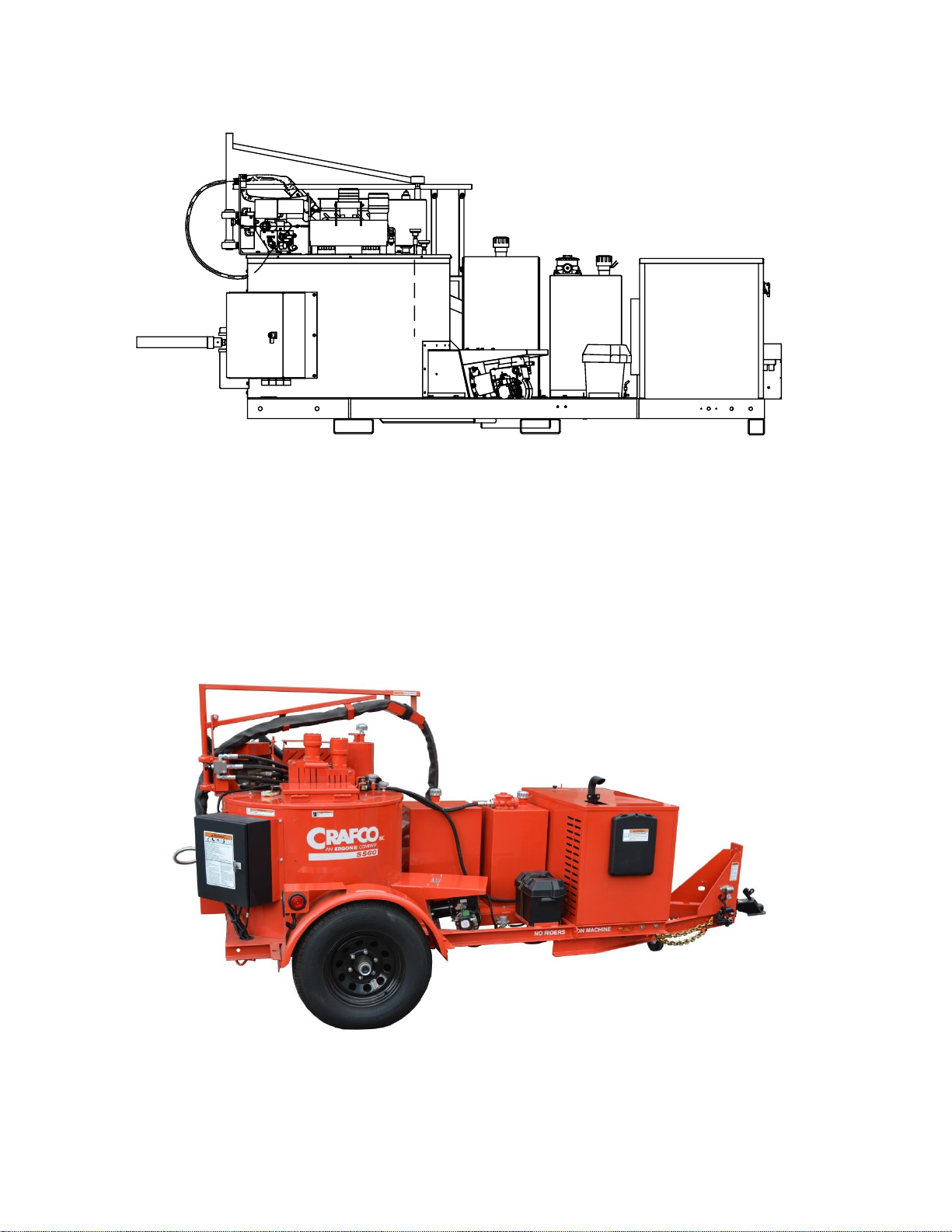
Figure 9.2 Super Shot 60 Diesel Trailer Melter..............................................................................9-6
Figure 9.3 Tank Assembly ..........................................................................................................9-10
Figure 9.4 Control Box Assembly................................................................................................9-12
Figure 9.5 Engine Assembly .......................................................................................................9-16
Figure 9.6 Hydraulic Control Valve Assembly: PN 45420............................................................9-18
Figure 9.7 Pump/Mixer Motor Assembly: PN 44832....................................................................9-20
Figure 9.8 Diesel Burner Assembly: PN 46380 ...........................................................................9-22
Figure 9.9 Hydraulic Diagram: PN 46959....................................................................................9-24
Figure 9.10 Electrical Schematic.................................................................................................9-28

Super Shot 60 Diesel Melter Part
Manual
List of Tables
Table 2-1 Safety Symbols and Notices......................................................................................... 2-2
Table 2-2 Safety Symbols and Notices (continued)....................................................................... 2-3
Table 4-1 Machine Specifications ................................................................................................. 4-1
Table 5-1 Preparing the Machine for Start Up............................................................................... 5-1
Table 5-2 Starting the Burner........................................................................................................ 5-3
Table 5-3 Electric Hose Care........................................................................................................ 5-6
Table 5-4 Hose for Transport Instructions..................................................................................... 5-6
Table 5-5 Loading Material into the Sealant Tank......................................................................... 5-7
Table 5-6 Material Tank Depth Chart............................................................................................ 5-8
Table 5-7 Dispensing the Material ................................................................................................ 5-9
Table 5-8 Shutting Down the Machine........................................................................................ 5-10
Table 6-1 Maintenance Chart........................................................................................................ 6-3
Table 6-2 Service Instructions....................................................................................................... 6-4
Table 6-3 General Maintenance Parts .......................................................................................... 6-4
Table 6-4 Recommended Spare Parts.......................................................................................... 6-5
Table 6-5 Recommended Fluids and Lubricants........................................................................... 6-5
Table 6-6 Applicable Brand of Heat Transfer Oil........................................................................... 6-6
Table 6-7 Material Pump Replacement......................................................................................... 6-7
Table 6-8 Material Pump Replacement (continued)...................................................................... 6-8
Table 8-1 Basic Visual Burner Troubleshooting............................................................................ 8-1
Table 8-2 Basic Visual Burner Troubleshooting (continued).......................................................... 8-2
Table 8-3 Burner Electrical Troubleshooting................................................................................. 8-2
Table 8-4 Burner Electrical Troubleshooting (continued)............................................................... 8-3
Table 8-5 Burner Electrical Troubleshooting (continued)............................................................... 8-4
Table 8-6 Burner Electrical Troubleshooting (continued)............................................................... 8-5
Table 8-7 Smoke Coming Out of Exhaust Stack........................................................................... 8-7
Table 8-8 Burner Lights But Shuts Down After 15 Seconds.......................................................... 8-7
Table 8-9 Testing the DC Controller.............................................................................................. 8-8
Table 8-10 Burner Fuel Solenoid Testing...................................................................................... 8-8
Table 8-11 Burner Ignition Coil Testing......................................................................................... 8-9
Table 8-12 Bleeding the Burner.................................................................................................... 8-9

Super Shot 60 Diesel Melter Part
Manual
List of Tables
Table 8-13 Sealant is Heating Slowly..........................................................................................8-11
Table 8-14 Basic Visual Mixer Troubleshooting...........................................................................8-12
Table 8-15 Mixer Electrical Troubleshooting ...............................................................................8-13
Table 8-16 Mixer Electrical Troubleshooting (continued).............................................................8-14
Table 8-17 Mixer Electrical Troubleshooting (continued).............................................................8-15
Table 8-18 Mixer Hydraulic Troubleshooting...............................................................................8-18
Table 8-19 Basic Visual Hose Troubleshooting...........................................................................8-21
Table 8-20 Hose Electrical Troubleshooting................................................................................8-21
Table 8-21 Hose Electrical Troubleshooting (continued).............................................................8-22
Table 8-22 Trigger is not Working...............................................................................................8-26
Table 8-23 RTD Sensor Ohms vs. Temperature.........................................................................8-27
Table 8-24 RTD Sensor Ohms vs. Temperature (continued).......................................................8-28
Table 8-25 Basic Visual Pump Troubleshooting..........................................................................8-29
Table 8-26 Pump Electrical Troubleshooting...............................................................................8-30
Table 8-27 Pump Electrical Troubleshooting (continued)............................................................8-31
Table 8-28 Pump Electrical Troubleshooting (continued)............................................................8-32
Table 8-29 Pump Electrical Troubleshooting (continued)............................................................8-33
Table 8-30 Pump Electrical Troubleshooting (continued)............................................................8-34
Table 8-31 Pump Hydraulic Troubleshooting ..............................................................................8-35
Table 9-1 Super Shot 60 Diesel Skid Mount Melter: PN 46800.....................................................9-3
Table 9-2 Super Shot 60 Diesel Skid Mount Melter: PN 46800 (continued)...................................9-4
Table 9-3 Super Shot 60 Diesel Trailer Melter: PN 46950.............................................................9-7
Table 9-4 Super Shot 60 Diesel Trailer Melter: PN 46950 (continued)..........................................9-8
Table 9-5 Super Shot 60 Diesel Trailer Melter: PN 46950 (continued)..........................................9-9
Table 9-6 Tank Assembly ...........................................................................................................9-11
Table 9-7 Control Box Assembly.................................................................................................9-13
Table 9-8 Control Box Assembly (continued)..............................................................................9-14
Table 9-9 Engine Assembly........................................................................................................9-17
Table 9-10 Hydraulic Control Valve Assembly: PN 45420...........................................................9-19
Table 9-11 Pump/Mixer Motor Assembly: PN 44832...................................................................9-21
Table 9-12 Diesel Burner Assembly: PN 46380 ..........................................................................9-23

Super Shot 60 Diesel Melter Part
Manual
List of Tables
Table 9-13 Hydraulic Diagram: PN 46959................................................................................... 9-25
Table 9-14 Hydraulic Diagram: PN 46959 (continued)................................................................ 9-26
Table 9-15 Electrical Schematic.................................................................................................. 9-29

Super Shot 60 Diesel Melter Part
Manual
Chapter 1 Introduction
©2016 by Crafco, Inc. All Rights Reserved …….. Introduction 1-1
1.0 About This Manual
This manual is supplied with each new Crafco Super Shot 60 Diesel Melter. The manual assists
your machine operators in the proper use of the melter applicator and provides information about
the machine’s mechanical functions.
Your Crafco Super Shot 60 Diesel Melter is specially made to give excellent service and save
maintenance expense. However, as with all specially engineered equipment, you get best results at
minimum cost if you:
Operate your machine as instructed in this manual.
Maintain your machine regularly as stated in this manual.
1.1 How to use this manual:
This manual is formatted to start each new chapter on the right page. There may be a blank page
on the left page if the previous chapter ends on the right page.
If you are viewing this in a digital format (PDF) the following features are available:
1. The Table of Contents, List of Tables, and List of Figures are all hyperlinks, when left
mouse clicked on section, table, or figure you will be sent to that page.
2. The blue highlighted text throughout the manual is a hyperlink, when left mouse clicked you
will be sent to that page, table, or figure.
3. The panel to the left in the PDF is a bookmarks panel, if you left mouse click on any
section/heading in the bookmarks panel you will be sent to that page.
4. There is an attachments icon (paper clip) to the left of the bookmarks, this is where you will
find full size prints of the control box, electrical, and hydraulic schematics.
WARNING
California Proposition 65 Warning
Engine exhaust and some of its constituents are known to the State of
California to cause cancer, birth defects, and other reproductive harm. Always
use care to avoid breathing engine exhaust. Failure to comply could result in
death or serious injury.


Super Shot 60 Diesel Melter Part
Manual
Chapter 2 Safety
©2016 by Crafco, Inc. All Rights Reserved………………………………………..…………………………………Safety 2-1
2.0 Safety Precautions
For more in-depth safety information, please see Safety Manual (PN 26221) which comes with the
machine. Or contact your nearest authorized Crafco Distributor at crafco.com/Distributors.
2.1 General Safety
Crafco, Inc. assumes no liability for an accident or injury incurred through improper use of
the machine.
Read this manual thoroughly before operating the machine.
Obey all CAUTION and WARNING signs posted on the machine.
Make sure an operator fully knows how to operate the machine before using the machine.
2.2 Personal Safety
The high operating temperatures of this machine and the sealant it contains requires that
protective clothing, gloves, hard-soled shoes, and safety glasses or a face shield be worn at
all times by operators of the machine.
Prevent water from going into any part of the machine. If there is indication of water in the
heat transfer oil system, warm heating oil to 250-300°F (121.1-148.96°C) for 2 to 3 hours.
Bodily contact with hot sealant or heat transfer oil can cause severe burns.
If the mixer is not stopped before adding solid material, hot material can get on an operator’s
body and cause severe burns.
Keep hands, feet, and clothing away from all moving parts.
2.3 Equipment or Operational Safety
Do not operate the machine in buildings or work areas that do not have sufficient airflow.
Shut-down the burner and the engine before refilling the fuel tank.
Make sure mixer stops before adding solid material to the sealant tank. Lift the lid, place the
material on the lid and close the lid. The mixer should restart automatically.
Always keep a correctly maintained fire extinguisher near the machine and know how to use
it.
DO NOT heat transfer oil to a temperature of more than 525°F (273.9°C).
DO NOT put too much heat transfer oil in the reservoir. The expansion of oil while it heats
up can cause overflow. With the machine on level ground, check the oil each day before
starting the burner. Add oil to the top mark on the dipstick if required (at 70°F (21.1°C)). Use
only recommended heat transfer oil. Change the oil after 500 hours of machine operation, or
one year, whichever comes first.
Follow the operating instructions for starting and shutting down the burner. Instructions are
mounted on the control box on the machine.
Calibrate the temperature control operation after each 50 hours of machine operation. Refer
to section 6.9 Temperature Control Calibration.
Replace any hoses which show signs of wear, fraying or splitting.
Make sure all fittings and joints are tight and do not leak each time the machine is used.
Do not leave the machine unattended while the burner is lit.
Tighten all bolts and screws every 100 hours of machine operation.

Super Shot 60 Diesel Melter Part
Manual
Chapter 2 Safety
©2016 by Crafco, Inc. All Rights Reserved………………………………………..…………………………………Safety 2-2
2.4 Safety Symbols and Notices
Important safety symbols and notices are marked on the machine and in this manual. Failure to
comply could result in equipment damage, operational malfunction, serious injury, or death. Please
read and comply with all symbols and notices. The table below includes the most commonly used
symbols and notices.
Symbol
Item
Remarks
WARNING
Warning
Refers to possible bodily injury or death.
CAUTION
Caution
Refers to possible equipment damage or operational
malfunction.
Severe Burn Hazard
Hot material can cause severe burns.
Protective Shoes
Wear hard-soled work shoes.
Protective Gloves
Wear heat resistant gloves.
Protective Face or Eye Wear
Wear face shield or safety glasses.
Body Crush Hazard
Do not stand between trailer and hitch when hooking
melter to truck.
Table 2-1 Safety Symbols and Notices

Super Shot 60 Diesel Melter Part
Manual
Chapter 2 Safety
©2016 by Crafco, Inc. All Rights Reserved………………………………………..…………………………………Safety 2-3
Symbol
Item
Remark
Crush Hazard
Keep feet and legs clear.
Pinch Hazard
Keep hands and feet clear.
Exhaust Hazard
Avoid breathing engine exhaust.
Read Manual
Read and understand operator and safety manuals
before operating machine.
Table 2-2 Safety Symbols and Notices (continued)


Super Shot 60 Diesel Melter Part
Manual
Chapter 3 Warranty Information
©2016 by Crafco, Inc. All Rights Reserved………………………………………………………….…Warranty Information 3-1
3.0 Limited Warranty
Crafco, Inc., through Crafco or one of its affiliated distributors, will replace for the original purchaser
free of charge any parts found upon examination by the factory at Chandler, Arizona, to be
defective in material or workmanship. This warranty is for a period one year from in-service date,
but excludes engine or components, tires, and battery as these items are subject to warranties
issued by their manufactures.
Crafco, Inc. shall not be liable for parts that have been damaged by accident, alteration, abuse,
improper lubrication/maintenance, normal wear, or other cause beyond our control.
The warranty provided herein extends only to the repair and/or replacement of those components
on the equipment covered above and does not cover labor costs. The warranty does not extend to
incidental or consequential damages incurred as a result of any defect covered by this warranty.
All transportation and labor costs incurred by the purchaser in submitting or repairing covered
components must be borne by the purchaser. Crafco, Inc. specifically disavows any other
representation, warranty, or liability related to the condition or use of the product.
CAUTION
Use of replacement parts other than genuine Crafco parts may impair the safety or reliability of your
equipment and nullifies any warranty.

Super Shot 60 Diesel Melter Part
Manual
Chapter 3 Warranty Information
©2016 by Crafco, Inc. All Rights Reserved………………………………………………………….…Warranty Information 3-2
3.1 Warranty Claim Instructions
Crafco, Inc. warrants parts and machinery purchased through Crafco or one of its affiliated
distributors for one year from purchased or in-service date. If parts fail to function within the first
year of purchase, a return authorization number (RA) must be obtained. If the part was purchased
number or if purchased through a Crafco distributor please contact your distributor. Note: if the part
has a serial number associated with it, for example; a machine or electric hose or wand, this must
be furnished when requesting the RA number. The customer will be emailed or faxed an RA form
with all instructions to return the item to Crafco, Inc. See example. If the part is found to be within
the one year warranty period and has not been abused or modified, a credit will be issued to the
customer’s account or credit card. The customer may request the part be replaced instead of a
credit, if desired.
Wear items are not covered under Crafco, Inc. limited warranty. A wear item is defined as but not
limited to: material pumps, sealing tips, tires, etc.
Note: All engine warranties are covered through the engine manufacture. If you need information for
a distributor in your area please contact us and we will direct you to the closest engine distributor.
All parts returned are tested and evaluated. If the part has been modified in any way without prior
consent from a Crafco, Inc. representative, warranty is void.
Please follow the instructions stated below when calling in a Warranty Claim. Failure to follow these
procedures may be cause to void the warranty.
Call your local Crafco Distributor. If you do not know who your local distributor is, call a Crafco
Customer Service Representative, (Toll Free 1-800-528-8242) for name, location and telephone
number.
On contacting the distributor, be prepared to identify the serial number, model number, engine
number, engine manufacturer, and the date of purchase if available.
Should the cause of the malfunction be a defective part, the Distributor will advise you of the
procedure to follow for a replacement.
The warranty is valid only for parts, which have been supplied or recommended by Crafco, Inc.
If you have any additional questions regarding warrant repairs and parts, please do not hesitate to
call toll free 1-800-528-8242.
For Warranty:
Crafco, Inc.
25527 South Arizona Avenue, Chandler, AZ
85248
Phone: (480) 655-8333 or (800) 528-8242
Fax: (480) 655-1712
For all other inquires:
Crafco, Inc.
6165 W Detroit St, Chandler, AZ 85226
Phone: (602) 276-0406 or (800) 528-8242
Fax: (480) 961-0513
CustomerServ[email protected]
.
Table of contents
Other Crafco Construction Equipment manuals


