IMT 9/63 User manual

99903278 : IM-9/63: PAGE 1:
Instruction Manual
IOWA MOLD TOOLING CO., INC.
BOX 189, GARNER, IA 50438-0189
TEL: 641-923-3711
TECHNICAL SUPPORT FAX: 641-923-2424
Model 9/63
NOTE
Read and understand this manual, the
IMT Operators Crane Safety Manual
and Safety Manual Supplement
before operating or maintaining your crane.
20061113
Iowa Mold Tooling Co., Inc. is an Oshkosh Truck Corporation company.
View thousands of Crane Specifications on FreeCraneSpecs.com
View thousands of Crane Specifications on FreeCraneSpecs.com

99903278 : IM-9/63: PAGE 2:
Table of Contents
20010507
Table of Contents ................................................................................................................................................... 2
Revisions List ......................................................................................................................................................... 2
1.0 Loader Terminology ........................................................................................................................................ 3
2.0 General Safety Considerations ..................................................................................................................... 3
3.0 Loader Operation ............................................................................................................................................ 4
3.1 Start-up Preparation ........................................................................................................................................ 4
3.2 Outrigger Activation ........................................................................................................................................ 5
3.3 Unfolding the Loader ...................................................................................................................................... 5
3.4 Using the Loader ............................................................................................................................................ 6
3.5 Post Operation ................................................................................................................................................ 7
4.0 Maintenance ................................................................................................................................................... 7
4.1 Lubrication Intervals ...................................................................................................................................... 7
4.2 Lubrication Chart ............................................................................................................................................ 8
4.3 Recommended Lubricants .............................................................................................................................. 8
5.0 Lifting Capacity ............................................................................................................................................... 8
5.1 Capacity Charts ............................................................................................................................................... 8
6.0 Technical Data ............................................................................................................................................... 13
7.0 Working Pressure / Performance ................................................................................................................ 14
8.0 Hydraulic System .......................................................................................................................................... 15
8.1 Description .................................................................................................................................................... 15
8.2 Recommended Hydraulic Oil Types ............................................................................................................ 15
8.3 Hydraulic Diagrams ...................................................................................................................................... 15
9.0 Bleeding of Cylinders ................................................................................................................................... 17
10.0 Repair .......................................................................................................................................................... 17
11.0 Service .......................................................................................................................................................... 17
11.1 Initial Service Overhaul ............................................................................................................................. 17
11.2 Annual Service Overhaul ........................................................................................................................... 18
12. Load Moment Limitation ............................................................................................................................... 18
13. Heavy Duty Lifting - HDL ............................................................................................................................... 18
14. Hoses and Hydraulic Pipes ........................................................................................................................... 18
DATE LOCATION DESCRIPTION OF CHANGE
-- -
Revisions List
20061113 1 NEW OWNERSHIP STATEMENT
View thousands of Crane Specifications on FreeCraneSpecs.com
View thousands of Crane Specifications on FreeCraneSpecs.com

99903278 : IM-9/63: PAGE 3:
1.0 Loader Terminology
The loader is designed as a truck mounted loader and therefore stationary mounting of the loader, mounting on
agricultural tractors, special purpose vehicles and the like may only be performed according to specific agreement
with IMT.
1. Suspension traverse
2. Control valve, loader
3. Outrigger / Stabilizer beam
4. Extension cylinder
5. Outrigger / Stabilizer leg
6. Control valve, stabilizers
7. Rotation / Slewing cylinder
8. Planetary gear
9. Boom cylinder
10. Base
11. Mast / Column
12. Link arm, boom
13. Hinge pin
14. Main boom
15. Outer / Jib cylinder
16. Outer / Jib pin
17. Link arm, jib
18. Outer boom / Jib
19. Extension
20. Extension cylinder
20010507
FIGURE 1:LOADER OVERVIEW
2.0 General Safety Considerations
WARNING
Prior to operation, read and understand the IMT Operator’s Crane Safety manual and any other safety manuals
which accompanied the loader.
General Considerations for Loader Safety and Stability
Prior to starting the loader, the operator must check the following factors:
1. Ground Stability - The ground must be stable enough to withstand the outrigger leg pressure. Steel plates should
be placed beneath the outrigger foot plates to support heavy lifts.
2. Ground Surface Conditions - The ground must not be slippery (i.e., covered with ice, sand, etc.).When the parking
brake is applied, the truck must not skid or move during horizontal pressure from the loader.
3. Visibility - The operator must have a complete and unobstructed view of the field of operation.
4. Overhead Powerlines - The operator must make sure that there are no electric wires or any other obstacles within
the working radius of the loader.
5. Unauthorized Entry - The operator must inform any unauthorized persons that entry into the working area is not
permitted.
View thousands of Crane Specifications on FreeCraneSpecs.com
View thousands of Crane Specifications on FreeCraneSpecs.com

99903278: IM-9/63: PAGE 4:
DANGER
Maintain safe clearance from electrical lines.
Allow for boom,electrical line, and loadline swaying.
This crane does not provide protection from contact
with or proximity to an electrically charged conductor.
Maintain a clearance of at least 10 feet between
any part of the crane, loadline or load and any electrical
line carrying up to 50,000 volts (50 kV). If electrical
line voltage is unknown, assume maximum voltage
and maintain a clearance of at least 45 feet.
NOMINAL VOLTAGE, kV MINIMUM REQUIRED
(Phase to Phase) DISTANCE
to 50_____________10 feet
Over 50 to 200_____________15 feet
Over 200 to 350_____________20 feet
Over 350 to 500_____________25 feet
Over 500 to 750_____________35 feet
Over 750 to 1000_____________45 feet
ELECTROCUTION HAZARD
THIS CRANE IS NOT INSULATED
WILL RESULT FROM CONTACT
OR INADEQUATE CLEARANCE
DEATH OR SERIOUS INJURY
20010507
FIGURE 2:
DECAL DANGER,
ELECTROCUTION
General Rules for Powerlines or Power Supply Stations
When working in proximity to power supply stations or overhead wires, follow these general rules:
1. Be careful in planning, instructing, and executing work to prevent any risk or danger to persons, equipment or
goods.
2. onsider any power supply plant, installation or wire live until proven otherwise.
3. Follow any and all directions or guidelines from the responsible power supply authorities .
Any person or company directly responsible for the implementation of work in the proximity of overhead wires or
electric power stations must make sure that all personnel involved in the execution of such work is familiar with any
laws, rules or safety regulations.
3.0 Loader Operation
3.1 Start-up Preparation
I. Switch the hydraulic change-over valve to the loader position.
II. Engage the PTO at low revolutions. The engine revolution speed is regulated
via the hand accelerator to ensure that the oil flow from the hydraulic pump
corresponds to the recommended pump flow for the loader. If starting the loader
in cold weather, the oil should circulate for a few minutes before operation
starts.
III. Apply the vehicle parking brake.
IV. R L System - Prior to setting the outriggers or starting loader operations,
the R L (rated-capacity limitation) system must be activated. To activate the
R L system, pull out the emergency stop button(s). Push the green button
once. The RUN diode on the R L system control panel (Figure 3) is lit and
the R L safety system is activated.
FIGURE 3: RCL 5100 CONTROL
PANEL
View thousands of Crane Specifications on FreeCraneSpecs.com
View thousands of Crane Specifications on FreeCraneSpecs.com

99903278: IM-9/63: PAGE 5:
3.2 Outrigger Activation
I. To activate the outrigger function, push the yellow button. The FUNC and F diodes are
lit. After 10 seconds the diodes are turned off, but the outrigger function remains activated.
II. To set the outriggers, release the outrigger lock and extend the outrigger beam completely.
LOCK IT AGAIN. The stability of the vehicle and the loader is based on the outrigger legs being
fully deployed, and the loader should only be used when the outriggers are fully deployed. The
operator must make sure that the vehicle has sufficient stability in the area in front of the
outriggers (over the cab).The outriggers should be lowered just enough to raise the truck chassis
slightly, while keeping the tires in full contact with the ground.
When loading the truck, the operator must raise the outrigger legs periodically to ensure that the truck and not the
outriggers carry the weight. The outrigger legs are not designed to support a fully loaded truck.
III. Position the vehicle as close to horizontal as possible. Use the outriggers if necessary to achieve horizontal
positioning if the ground is not level.
IV. Use plates (steel) beneath the outrigger legs if the ground cannot support the outrigger leg pressure.
3.3 Unfolding the Loader
I. Extend outrigger beams fully and
engage swivel locks.
II. Lower the outrigger legs.
III. Lower the outer boom slightly to release it from the bracket.
IV. Raise the inner (main) boom to release it from the
bracket. Raise the inner (main) boom about 10° above
horizontal so that the outer boom can be moved freely downwards.
V. Raise the outer boom (jib) until it is free from the base.
VI. If the loader is equipped with a stop bracket on the outer boom, extend the extension booms until the stop
bracket is released.
20010507
FIGURE 4:
OUTRIGGER LOCK
FIGURE 5: UNFOLDING A KNUCKLE-BOOM CRANE FIGURE 6: STOP BRACKET
View thousands of Crane Specifications on FreeCraneSpecs.com
View thousands of Crane Specifications on FreeCraneSpecs.com

99903278: IM-9/63: PAGE 6:
3.4 Using the Loader
Loader Valve Bank Activation
To activate the loader working functions, move one of the control levers of the loaders control valve OR Push the
yellow button twice. FUN is lit and F5 is turned off.
Now the loader functions can be operated using the control valves. Each control valve is labeled with the functions of
that particular valve. See Figure 7 for the control valve functions. Operate the control levers steadily and smoothly to
avoid unnecessary strain on the loader.
The lifting capacity of the loader is shown on the apacity hart on the loader and in this instruction manual. Never
exceed the indicated capacity limits.
The loader is designed to lift loads vertically. Diagonal stress must be avoided. Do not drag loads across the ground
using the extension cylinders or the rotation system. Activate these functions when the load is free of the ground.
When mounting a grapple, the total weight (grapple, rotator, and contents) must not exceed the lifting capacity of the
loader at maximum reach. The grapple may be used to move soil only. It must not be used to excavate earth.
If the load is extended so far that the lifting capacity is exceeded, the load moment increasing movements will be
stopped. See the R L Safety System Instruction Manual.
WARNING
Never stand under the boom when the loader is working.
NOTES FOR SAFE OPERATION:
Position the truck as closely to the load as possible to lift the load on the shortest possible boom.
Operate the rotation system carefully, especially when the inner boom is at an acute angle to the outer boom.
Do not activate the outriggers when the loader is working.
Never drive off with a suspended load.
20010507
FIGURE7: CONTROL VALVES
View thousands of Crane Specifications on FreeCraneSpecs.com
View thousands of Crane Specifications on FreeCraneSpecs.com

99903278: IM-9/63: PAGE 7:
3.5 Post Operation
To stow the loader, reverse the procedure in Section 3.3, Unfolding the Loader. If the boom is parked on the truck
platform, it must be properly secured so it does not swing out during transport. The total height should not exceed
13 6 per Federal Highway Regulations.
If the loader is equipped with swing-up outrigger legs, they must also be secured in position before driving off.
Before starting the vehicle, disengage the PTO. This turns off the pump.
4.0 Maintenance
Regularly check the items below on the loader. Log the inspection in the IMT Crane Log
included with the manual.
1. The oil level in tank and rotation system. Oil must be visible in the oil level glass of the tank
when the loader is folded. If the loader is equipped with a planetary gear, check its oil level.
2. Check for defects, damage or leaks . If found, take the loader to an authorized IMT
service center for repair as soon as possible.
3. Check the loader to truck mounting hardware.
4. Slide blocks and bushings reduce friction and therefore they are naturally subject to wear. Slide blocks should be
replaced when slack is detected in the boom system. Bushings should be replaced before the metal components
physically touch each other.
5. Check all hoses for defects and kinks.
6. Check that hooks, straps and safety latches are in good working order.
7. Check all lock pins and bolts for wear.
4.1 Lubrication Intervals
Pinion of mast/Planetary gear (if any):
after 50 hours of operation/1 month (whichever occurs first)
Base bearings:
after 20 hours of operation/1 week (whichever occurs first)
Extension system/Slide blocks:
after 50 hours of operation/1 month (whichever occurs first)
Guide rail on extension cylinders:
after 50 hours of operation/1 month (whichever occurs first)
Pin connections/Bolts:
after 50 hours of operation/1 month (whichever occurs first)
Outrigger beams:
as required
Control al es and rod connections (Oil spray):
as required
FIGURE 8: OIL LEVEL
View thousands of Crane Specifications on FreeCraneSpecs.com
View thousands of Crane Specifications on FreeCraneSpecs.com

99903278: IM-9/63: PAGE 8: 20010507
4.2 Lubrication Chart
When lubricating the bearings in the base, activate the rotation system and swing the loader from stop to stop within
the entire rotation area.
Lubricate the telescopic extensions and planetary gear are lubricated with a special grease (Statoil Grease Way
Ca or Castrol ALV).
CAUTION
If the loader is not folded after use, retract all cylinders at least once per day to avoid corrosion on the
piston rod surface.
4.3 Recommended Lubricants
Grease Brand Grease for Bearings
BP Energrease L52
Castrol LM Grease
ESSO MP Grease I Beacon EP 2
Mobil Mobilux EP 2 or Mobilgrease P
Shell Retinox MS
Statoil Uni Way EP 2
Texaco Multifak All Purpose EP 2
Grease containing molybdenum disulphide must not be used.
Grease Brand Grease for Telescopic E tensions
Statoil Grease Way Ca 92
Castrol ALV
5.0 Lifting Capacity
5.1 Capacity Charts
The loader is marked with factory-installed lifting capacity decals. These decals must be intact and legible. If the
decal has been damaged or removed, order a new decal from IMT using the part number from the decal or consult
the parts manual, decal kit.
As a supplement to the loaders lifting capacity decals, the following pages contain load and lifting capacities of the
different K-versions in standard applications. Special applications and customized decals and options are not
shown.
WARNING
Never exceed the lifting capacity limits.
FIGURE 9: LOADER LUBRICATION POINTS
View thousands of Crane Specifications on FreeCraneSpecs.com
View thousands of Crane Specifications on FreeCraneSpecs.com

99903278 : IM-9/63: PAGE 9:
IOWA MOLD TOOLING CO., INC.
BOX 189 GARNER IA 50438 641-923-3711
llll
Model
9/63K1
l
Working loads will be limited to those shown.
Deduct the weight of load handling devices.
Before lift is made, stability must be checked
per SAE J765A.
l
70395973
0
MOUNTING
SURFACE
3'-0"
(0.91m)
-3'-0"
(-0.91m)
6'-0"
(1.83m)
9'-0"
(2.74m)
12'-0"
(3.66m)
15'-0"
(4.57m)
18'-0"
(5.49m)
21'-0"
(6.40m)
0
CENTERLINE
3'
(0.91m)
6'
(1.83m)
9'
(2.74m)
12'
(3.66m)
15'
(4.57m)
18'
(5.49m)
LBS
KGS
21'
(6.40m)
24'-0"
(7.32m)
27'-0"
(8.23m)
20010507
View thousands of Crane Specifications on FreeCraneSpecs.com
View thousands of Crane Specifications on FreeCraneSpecs.com

99903278 : IM-9/63: PAGE 10:
IOWA MOLD TOOLING CO., INC.
BOX 189 GARNER IA 50438 641-923-3711
llll
Model
9/63K2
l
Working loads will be limited to those shown.
Deduct the weight of load handling devices.
Before lift is made, stability must be checked
per SAE J765A.
l
70395974
0
MOUNTING
SURFACE
3'-0"
(0.91m)
-3'-0"
(-0.91m)
6'-0"
(1.83m)
9'-0"
(2.74m)
12'-0"
(3.66m)
15'-0"
(4.57m)
18'-0"
(5.49m)
21'-0"
(6.40m)
0
CENTERLINE
3' 6' 9' 12' 15' 18'
LBS
KGS
21'
24'-0"
(7.32m)
27'-0"
(8.23m)
24' 27'
30'-0"
(9.14m)
33'-0"
(10.06m)
20010507
View thousands of Crane Specifications on FreeCraneSpecs.com
View thousands of Crane Specifications on FreeCraneSpecs.com

99903278 : IM-9/63: PAGE 11:
IOWA MOLD TOOLING CO., INC.
BOX 189 GARNER IA 50438 641-923-3711
llll
Model
9/63K3
l
Working loads will be limited to those shown.
Deduct the weight of load handling devices.
Before lift is made, stability must be checked
per SAE J765A.
l
70395975
0
MOUNTING
SURFACE
3'-0"
(0.91m)
-3'-0"
(-0.91m)
6'-0"
(1.83m)
9'-0"
(2.74m)
12'-0"
(3.66m)
15'-0"
(4.57m)
18'-0"
(5.49m)
21'-0"
(6.40m)
0
CENTERLINE
3' 6' 9' 12' 15' 18'
LBS
KGS
21'
24'-0"
(7.32m)
27'-0"
(8.23m)
24' 27'
30'-0"
(9.14m)
33'-0"
(10.06m)
36'-0"
(10.97m)
30' 33'
20010507
View thousands of Crane Specifications on FreeCraneSpecs.com
View thousands of Crane Specifications on FreeCraneSpecs.com

99903278 : IM-9/63: PAGE 12:
IOWA MOLD TOOLING CO., INC.
BOX 189 GARNER IA 50438 641-923-3711
llll
Model
9/63K4
l
Working loads will be limited to those shown.
Deduct the weight of load handling devices.
Before lift is made, stability must be checked
per SAE J765A.
l
70395976
0
MOUNTING
SURFACE
3'-0"
(0.91m)
-3'-0"
(-0.91m)
6'-0"
(1.83m)
9'-0"
(2.74m)
12'-0"
(3.66m)
15'-0"
(4.57m)
18'-0"
(5.49m)
21'-0"
(6.40m)
0
CENTERLINE
3' 6' 9' 12' 15' 18'
LBS
KGS
21'
24'-0"
(7.32m)
27'-0"
(8.23m)
24' 27'
30'-0"
(9.14m)
33'-0"
(10.06m)
36'-0"
(10.97m)
30' 33' 36' 39'
39'-0"
(11.89m)
42'-0"
(12.80m)
20010507
View thousands of Crane Specifications on FreeCraneSpecs.com
View thousands of Crane Specifications on FreeCraneSpecs.com

99903278 : IM-9/63: PAGE 13:
6.0 Technical Data
Load moment K1 - 62930 ft-lb (8.7 tm) K2 - 61483 ft-lb (8.5 tm)
K3 - 58590 ft-lb (8.1 tm) K4 - 57867 ft-lb (8.0 tm)
Hydraulic reach K1 - 18.7 ft (5.7 m) K2 - 24.9 ft (7.6 m)
K3 - 30.8 ft (9.4 m) K4 - 37.1 ft (11.3 m)
Hyd. Telescopic movement K1 - .07” (1.8 mm) K2 - .14” (3.6 mm)
K3 - .21” (5.4 mm) K4 - .28” (7.2 mm)
Reach with Manual Ext. K1 - 23.9 ft (7.3 m) K2 - 30.2 ft (9.2 m)
K3 - 42.3 ft (12.9 m) K4 - 42.3 ft (12.9 m)
Standard loader weight, K1 - 2314 lb (1050 kg) K2 - 2513 lb (1140 kg)
excluding outriggers K3 - 2711 lb (1230 kg) K4 - 2888 lb (1310 kg)
Lifting speed at max. reach K1 - 3 ft/sec (.9 m/sec) K2 - 3.9 ft/sec (1.2 m/sec)
K3 - 3.6 ft/sec (1.1 m/sec) K4 - 4.3 ft/sec (1.3 m/sec)
Lifting capacity K1 - 5291 lb - 11.8’ (2400 kg - 3.6 m)
3571 lb - 17.7’ (1620 kg - 5.4 m)
K2 - 5071 lb - 12.14’ (2300 kg - 3.7 m)
3351 lb - 18’ (1520 kg - 5.5 m)
2535lb - 24’ (1150 kg - 7.3 m)
K3 - 4806 lb - 12.14’ (2180 kg - 3.7 m)
3153 lb - 18’ (1430 kg - 5.5 m)
2337 lb - 24’ (1060 kg - 7.3 m)
1863 lb - 29.8’ (845 kg - 9.1 m)
K4 - 4630 lb - 12.5’ (2100kg - 3.8 m)
2976 lb - 18.4’ (1350kg - 5.6 m)
1698 lb - 30.2’ (770kg - 9.2 m)
1411 lb - 36.1’ (640kg - 11.0m)
Lifting capacity, Man. Ext K1 - 2557 lb - 24’ (1160 kg - 7.3 m)
K2 - 1896 lb - 30.2’ (860 kg - 9.2m)
K3 - 1433 lb - 36.1’ (650 kg - 11.0m) 1212 lb - 42.3’ (550 kg - 12.9 m)
K4 - 1212 lb - 42.3’ (550 kg - 12.9 m)
Slewing torque 10054 ft-lb (1390 kg-m)
Slewing angle 400 °/sec
Max. heel at max. load moment 5 °/sec
Height above chassis when folded 7’1” (2130 mm)
Width when folded 7’10” (2350 mm)
Length, without extra valves 2’3” (680 mm)
Lenght, with extra valves 2’6” (740 mm)
Outrigger spread, standard 15’6” (4650 mm)
Outrigger spread, double ext. 19’2” (5750 mm)
Working speeds
Slewing speed 20 °/sec
Outrigger legs, standard 381 lb (173 kg)
Outrigger legs, double ext. 540 lb (245 kg)
Mounting bolts 116 lb (53 kg)
Oil in base and cylinders 88 lb (40 kg)
Standard tank with oil 123 lb (56 kg)
Power consumption /
pump performance
Working pressure 4567 PSI (31.5 MPa)
Pump performance 9.2 gpm (35 l/min)
Power consumption 18 KW
Oil capacity in base 7.4 gal (28 l)
Oil capacity in separate tank 11.1 gal (42 l)
20010507
View thousands of Crane Specifications on FreeCraneSpecs.com
View thousands of Crane Specifications on FreeCraneSpecs.com

99903278: IM-9/63: PAGE 14:
7.0 Working Pressure / Performance
The working pressure should be set with a pressure gauge. Keep the pressure below the limits as shown in the
following tables. Check the working pressure at least annually, and during ay major repair, following the procedure
described in the IMT Crane Log manual. ll adjustable valves must be resealed after pressure setting adjustment.
WORKING PRESSURE-9- 3
Basic position
during test and
adjustment of
valves
Working pressure on main-relief valve & port-relief valves
Function Port 02 03 04
Main-relief valve 4568 psi (31.5 MPa)
Stabilizer legs/ up -port 2175 psi (15.0 MPa)
grab, rotator down B-port 2175 psi (15.0 MPa)
-port 2175 psi (15.0 MPa)
-port 2175 psi (15.0 MPa)
Inner boom cylinder down -port 1813 psi (12.5 MPa)
up B-port 4713 psi (32.5 MPa)
Outer boom cylinder up -port 3988 psi (27.5 MPa)
down B-port 2538 psi (17.5 MPa)
Extension extend -port P
cylinders retract B-port P
Rotation system right -port 2175 psi (15.0 MPa)
left B-port 2175 psi (15.0 MPa)
Separate outrigger 2175 psi (15.0 MPa)
valve
Opening pressure on load holding valves
Inner boom cylinder 4931 psi (34.0 MPa)
Outer boom cylinder 3988 psi (27.5 MPa)
Extension cyl C1-V1 retract B-port 6236 psi (43.0 MPa)
Extension cyl C2-V2 extend -port 3045 psi (21.0 MPa)
External relief valve
Pressure setting for load moment limitation
LMB 4423 psi (30.5 MPa)
Max. Pump performance
Pump performance K2 9.25 gpm (35 l/min)
Pump performance K3-K4 7.93 gpm (30 l/min)
20010507
FIG RE 10: WORKING PRESS RE VALVE TEST/ADJ STMENT POSITION
View thousands of Crane Specifications on FreeCraneSpecs.com
View thousands of Crane Specifications on FreeCraneSpecs.com

99903278 : IM-9/63: PAGE 15:
8.0 Hydraulic System
8.1 Description
The loader valve block is a “stack” type, consisting of a number of separate control valves. A main relief valve is fitted
in the inlet section of the valve block to ensure that the oil pressure in the pump line does not exceed the
permissible limit. This valve is adjustable and must always remain sealed.
Port relief valves are mounted at the ports of the individual control valves to limit the pressure in the individual
circuits. The port relief valves are pre-set and not adjustable.
The inner, outer, and extension cylinders are mounted with load holding valves with the following functions:
1. Protect cylinders against excessive pressure.
2. Speed control when the boom is lowered.
3. To maintain the boom in position during operations where a fixed boom position is required.
4. Lock the boom and maintain the load in position in case of hose or pipe rupture.
The outrigger cylinders are equipped with a piloted check valve that locks the cylinder in case of damage to the
hydraulic system.
CAUTION
The main relief valve, the load holding valves, the dump valve and the external relief valve are sealed. Check these
seals regularly and have an authorized IMT service center replace them if damaged.
8.2 Recommended Hydraulic Oil Types
Oil Brand Oil Type Low Temp Oil Type
BP Bartran HV 32 Bartran HV 22
Castrol Hyspin AWS 32 Hyspin AWH 32
ESSO Nuto H 32 Univis N 22
Mobil DTE 13 DTE 11
Shell Tellus S 32 Tellus T 32
Statoil Hydra Way HM 32 Hydra Way HV 22
Texaco Rando HD 32 Rando HDZ 32
8.3 Hydraulic Diagrams
The following page contains the hydraulic diagram for the loader in standard application. There may be changes in
design of the hydraulic system when applied to special and/or customized loaders. In these cases refer to the
supplementary documentation.
20010507
View thousands of Crane Specifications on FreeCraneSpecs.com
View thousands of Crane Specifications on FreeCraneSpecs.com

99903278 : IM-9/63: PAGE 16:
STANDARD HYDRAULIC DIAGRAM
20010507
View thousands of Crane Specifications on FreeCraneSpecs.com
View thousands of Crane Specifications on FreeCraneSpecs.com

99903278 : IM-9/63: PAGE 17:
9.0 Bleeding of Cylinders
If air has entered the hydraulic system, bleed the air from the loader.
1. Raise and lower each outrigger leg twice.
2. Extend and retract the inner boom cylinder twice.
3. Extend and retract the outer cylinder twice with the inner boom pointing downward, and twice with the
inner boom pointed upward.
4. Extend and retract the extension cylinder twice with the outer boom pointed almost vertically upward, and twice
with the outer boom pointed almost vertically downward.
10.0 Repair
If defects, damage or leaks are found, repair them immediately. Always have your repairs performed by an
authorized IMT service center. Repairs to the hydraulic system must be made only at an authorized service center.
When ordering parts for your loader, please state:
• Loader model (9/63)
• Loader serial number (found on serial number placard on loader)
11.0 Service
11.1 Initial Service Overhaul
The initial service overhaul is recommended after the first 20 hours of service or after one month of loader use,
whichever comes first.
The service overhaul should include:
1. Change of return filter element and high pressure filter cartridge, if applicable.
2. The oil level in tank and rotation system. Oil must be visible between maximum and minimum lubrication on the
oil level rod, when the loader is in the folded position. The oil level in the slewing system should also be visible in the
inspection tube.
3. Overall lubrication according to the lubrication chart in this manual.
4. Leak check and tightening of fittings, if required.
5. Checking of working pressure and lead seals. The correct working pressures are stated in Section 7.0.
6. Test all functions under load.
7. Checking and, if required, tightening of mounting bolts and pin connections.
8. Checking of all lock bolts and pins.
20010507
View thousands of Crane Specifications on FreeCraneSpecs.com
View thousands of Crane Specifications on FreeCraneSpecs.com

99903278 : IM-9/63: PAGE 18:
11.2 Annual Service Overhaul
Each year the loader should be given a complete service overhaul at an authorized IMT service center. The service
check must include:
1. Oil change for hydraulic oil in tank and rotation system.
2. Filter change for return filter element and high pressure filter cartridge.
3. Air filter cleaning or replacement.
4. Working pressure and valve lead seal check.
5. Idling pressure check.
6. Complete function test under load.
7. Check slide blocks and bearing bushings for wear. Replace if necessary.
8. Check hydraulic hoses.
9. Leak check and tighten all connections.
10. Check pump and transmission.
11. Check loader base to chassis mounting hardware.
12. Check all bolt connections. Tighten if required.
13. Check overallloader structure for damage. Any damage found should be repaired immediately.
14. Check bolts and lock plates.
20010507
12. Load Moment Limitation
The loader is equipped with a load moment limitation system (LMB). THis system ensures that the permissible load
moment is never exceeded, irrespective of the operator’s doings.
However, it is important to keep in mind that the LMB-system does not necessarily ensure sufficient vehicle stability.
Before starting to work with the loader, the operator must always make sure that the vehicle is stable in the entire
slewing area of the loader. However, if the loader is equipped with an EVS-system (Electronic Vehicle Stability), the
stability of the vehicle is ensured in the entire working area, because the system is constantly checking the vehicle,
and immediately stopping the load moment increasing movement in case of instability, irrespective of the operator’s
doings.
Note
The RCL system is described in detail in the Instruction Manual - RCL Safety System. The loader
operator should be familiar with the RCL system.
13. Heavy Duty Lifting - HDL
If the loader is equipped with a Heavy Duty Lifting (HDL) system, the loader can attain an increased lifting capacity
at reduced speed.
When the loader reaches its normal lifting capacity limit, the HDL-system will automatically be activated and the oil
flow to the control valve will be reduced to approximately 20 percent of the normal oil flow. At the same time, the
loader lifting capacity is increased by approximately 10 percent in the entire working area of the loader. When the
HDL-system is activated, the operator will be able to continue extending the load without interruption, although at
reduced speed.
If the load moment is reduced to permitted load limits again, the HDL-system will increase the oil flow to normal and
the working speed will increase again. However, the automatic disconnection implies that all control levers have
been into neutral position at the same time as the load moment has been reduced to the permitted load limit.
Please also see chapter on “Heavy Duty Lifting, HDL” in the manual: Instruction Manual - RCL Safety System.
14. Hoses and Hydraulic Pipes
The hoses must comply with the SAE R100 2AT standard.
The pipes are manufactured in St.35.4C-NBK.
View thousands of Crane Specifications on FreeCraneSpecs.com
View thousands of Crane Specifications on FreeCraneSpecs.com

99903278 : IM-9/63: PAGE 19:
IOWA MOLD TOOLING CO., INC.
BOX 189, GARNER, IA 50438-0189
TEL: 641-923-3711
TECHNICAL SUPPORT FAX: 641-923-2424
20010507
View thousands of Crane Specifications on FreeCraneSpecs.com
View thousands of Crane Specifications on FreeCraneSpecs.com
Table of contents
Other IMT Construction Equipment manuals
Popular Construction Equipment manuals by other brands

Jerr-Dan
Jerr-Dan MPL40 Operation and safety manual
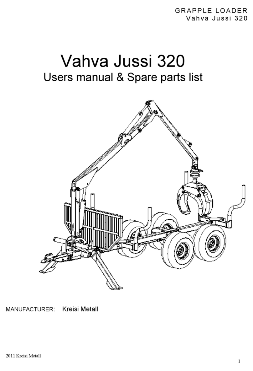
Vahva Jussi
Vahva Jussi 320 Users manual & Spare parts list
Manitowoc
Manitowoc MLC650 Operator's manual
Roper Whitney
Roper Whitney MBB 4181 MAGNABEND Operation, parts & maintenance manual
Weiler
Weiler E2850 Operator and maintenance manual

stellar labs
stellar labs 13500 owner's manual
