Tornomeccanica Securpulley Manual
OPERATING AND MAINTENANCE INSTRUCTIONS
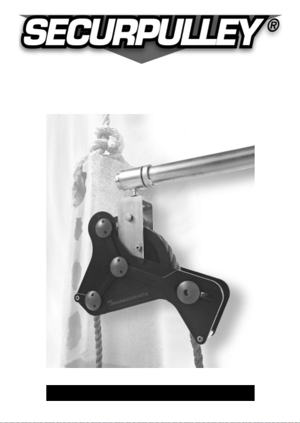
PULLEY WITH SAFETY BRAKE
FOR THE BUILDING INDUSTRY
by TORNOMECCANICA s.r.l.

TORNOMECCANICA s.r.l.
Genova • Via Renata Bianchi 67N
Tel: 010 650 94 04
Telefax: 010 650 94 05
SHEAVE FOR BUILDING INDUSTRY
WITH SAFETY BRAKE
MODEL: SECURPULLEY®
SAFE WORKING LOAD:50 KG
TORNOMECCANICA 99112036.1-2309

INDEX
1. PURPOSE OF THE INSTRUCTION MANUAL pag. 1
2. SPECIFICATIONS: 1
3. FORESEEN USE AND SAFE USE OF THE SHEAVE
3.1 Generals
2
3.2 General directions for the safe use
2
4. DESCRIPTION AND FUNCTIONING OF THE SHEAVE
4.1 Descripition
3-4
4.2 Functioning
5-6
5. INSTRUCTIONS OF INSTALLATION AT THE WORKING PLACE
7-8
6. INSTRUCTIONS FOR USE
6.1 Generals
9
6.2 Insertion of the rope into the sheave
10
6.3 Regulation of the counterweight according to the lifting height
11
6.4 Check of the wedge-pressing bush for adapting to the rope diameter
12
6.5 Functional test before use
13
6.6 Lifting of loads (building of scaffolds)
14-15
6.7 Descent to ground of the empty rope
16
6.8 Lifting of the empty rope to the floor (scaffolds dismantling)
17
6.9 Lowering of loads
17
7. TROUBLE SHOOTING 18
8. INSTRUCTIONS FOR MAINTENANCE AND PERIODICAL CHECK
8.1 Generals
19
8.2 Periodical check and maintenance
20
8.3 Substitution of parts
21
•
8.3.1 Substitution of the wedge- brake
21
•
8.3.2 Substitution of the rope reeving roller
21
•
8.3.3
Substitution of the spacers counterweight side and reeving roller side
21
•
8.3.4 Substitution of shaft and knobs of the counterweight
21
9. SPARE PARTS
22
10. WARRANTY
22
Graphic symbols used in the manual:
= important remark: consider carefully
= warning of possible danger

1. PURPOSE OF THE INSTRUCTION MANUAL
These instructions are done in conformity with the requirements of the Machinery
Directive (89/392 CEE) para. 1.7.4, 4.4.2 - Enclosure 1.
They give the directions for the correct and safe execution of:
- installation at the working place
- use
- maintenance and periodical check
It is very important that the instructions are available to the personnel charged with
the said operations, and clearly understood by it, before the execution of the operations
themselves.
The manual is integral part of the supply of the machine and must be kept with care
and kept at the users’ disposal.
In case of incomprehension of the explanations of the manual, of malfunctioning or for
repair interventions that do not belong to the foreseen maintenance, please contact
our After Sale Service.
2. SPECIFICATIONS:
WEIGHT: kg 5
MAXIMUM WORKING LOAD: kg 50
MINIMUM WORKING LOAD: kg 8÷10
MAXIMUM SUGGESTED WORKING HEIGHT: m 30
MAXIMUM WORKING HEIGHT: m 40
ROPE DIAMETERS TO BE USED: mm 18
mm 20
SUPPORTING ON STANDARD SCAFFOLDING PIPE
EXTERNAL DIAMETER: mm 48
FOR THE GOOD RUNNING AND THE SAFETY OF “SECURPULLEY®”
WE SUGGEST TO USE OUR FAST RELEASE SUPPORT (O SYSTEM).
INSTRUCTION MANUAL FOR SAFETY SHEAVE
pag. 1
by TORNOMECCANICA s.r.l.

INSTRUCTION MANUAL FOR SAFETY SHEAVE
pag. 2
by TORNOMECCANICA s.r.l.
3. FORESEEN USE AND SAFE USE OF THE SHEAVE
3.1 Generals
For using the sheave without dangers it is necessary to
follow the instructions contained in this manual.
The sheave SECURPULLEY® is foreseen for manual lifting and lowering of loads during
building and dismantling of scaffoldings.
SECURPULLEY‚introduces in this working ambient a new and basic safety concept: the
warranty of an automatic braking of the load as the human effort on the rope ceases.
3.2 General directions for the safe use
Do not install and use the sheave in a different way from this manual indicates.
The manufacturer does not respond for any damage due to improper use or neglecting
the safety measures.
The working area must respond to the safety requirements foreseen by the law.
In particular it is forbidden to stay below the suspended loads.
Do not use the sheave for lifting heigths or loads exceeding the values indicated at
chapter 2.
Do not use ropes of diameters different from the ones indicated at chapter 2.
Do not use ropes with the diameter reduced by wear below the minimum diameter
indicated at chapter 2, nor with strands deformed o damaged.
The malfunctioning
of the sheave and the possible troubles coming out from the use of a
damaged rope are under the only responsibility of the user.
Before starting the use of the sheave, check the correct positioning of the setting
counterweight related to the working height and rope weight, and test the braking
efficiency
For the use of SECURPULLEY® always wear safety gloves and shoes, beyond to other
safety individual protection means if any, foreseen by the safety plan of the yard.
Store the sheave in a dry and clean ambient; after the use in presence of powder,
clean the sheave, preferably by a compressed air stream.
Do not eliminate, nor substitute with not original spare parts any component of the
sheave, not to risk compromising its safety features.
Detailed safety directions for installation, use and maintenance are given in chapters
5, 6, 7, 8.

4. DESCRIPTION AND FUNCTIONING OF THE SHEAVE
4.1 Description
The sheave SECURPULLEY‚ is a Tornomeccanica patent: it is marked with the CE mark
in conformity with the Machinery Directive on the safety of the machinery and is
supplied with the CE Conformity Declaration.
Overload static tests with 400% of rated load have been succesfully done on one
prototype.
Each unit is tested with 150% overload.
These tests conform to the standard prEN 13157
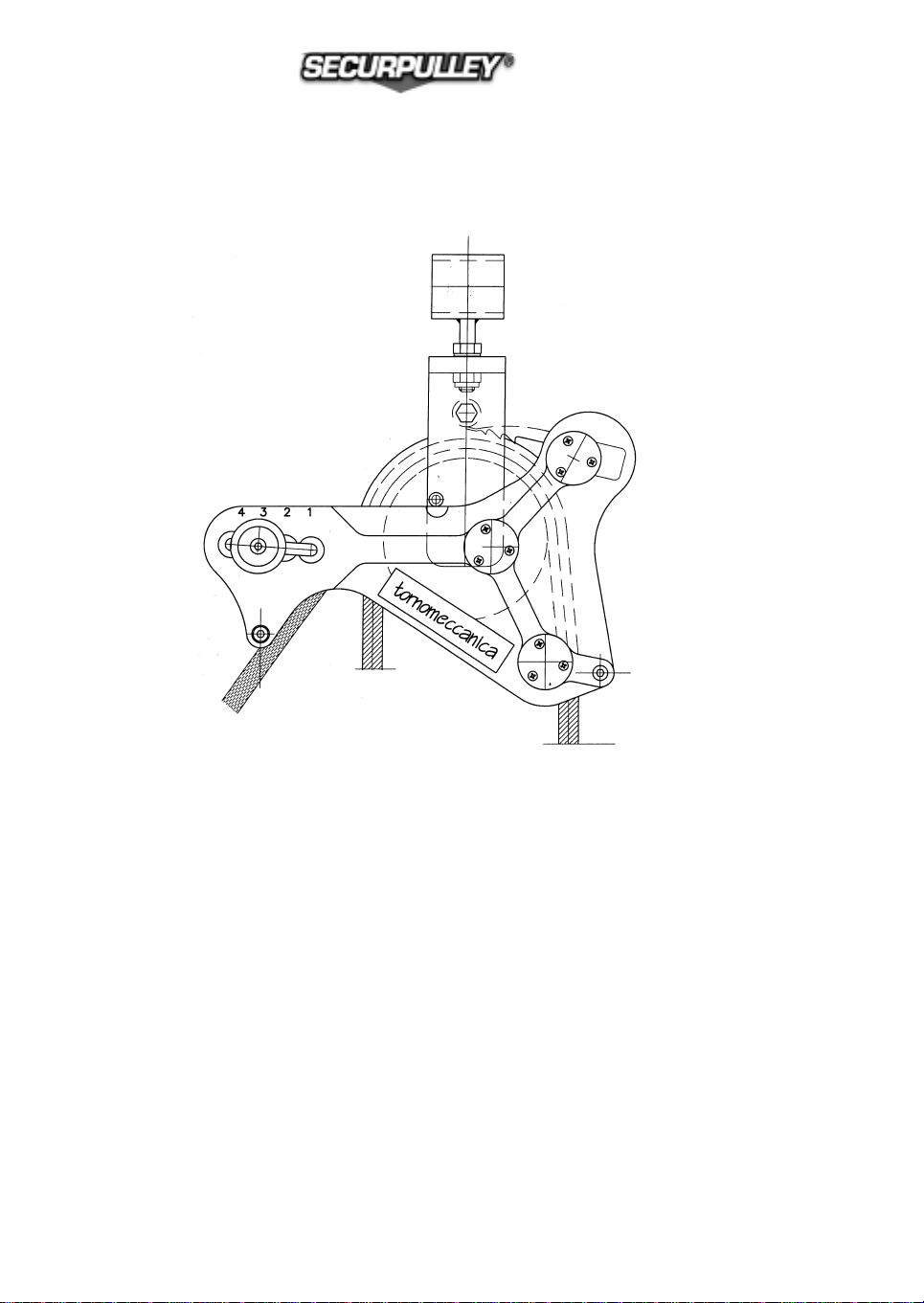
Figure 1: SECURPULLEY assembly
Legenda:
1.Rotating sleeve
2.Supporting bracket
3.Sheave axle
4.Sheave
5.Side plates
6.Reeving roller
7.Wedge-brake
8.balancing counterweight
9.counterweight unlocking screws
10.spacers counterweight side and reeving roller side
INSTRUCTION MANUAL FOR SAFETY SHEAVE
pag. 3
by TORNOMECCANICA s.r.l.

The rotating sleeve 1allows to safely fix the sheave to the supporting point and allows its
oscillation in a vertical plane.
The bracket 2is slewing relative to the sleeve 1, so that the whole body of the sheave
assembly can rotate in comparison with such support.
The bracket 2houses the axle 3on which the sheave 4is arranged, through small rollers
bearings.
The two side plates 5are fixed to the bracket 2and are rotating around an axle eccentric
relative to the sheave axle.
In turns, the two side plates bears the reeving roller 6, the floating wedge-brake ≤and the
balancing counterweight 8.
La counterweight 8position setting is done by the loosening of the screws 9which requires,
for safety reasons, of a special key supplied with the sheave.
The spacer located on the “fore” part of SECURPULLEY®‚ allows unlocking the brake,
operating the rope from the height for the descent at no load.
The spacer located on the “rear” part of SECURPULLEY®‚ has an anti-spooling function for
the rope.
INSTRUCTION MANUAL FOR SAFETY SHEAVE
pag. 4
by TORNOMECCANICA s.r.l.
INSTRUCTION MANUAL FOR SAFETY SHEAVE
pag. 5
by TORNOMECCANICA s.r.l.
4.2 FUNCTIONING
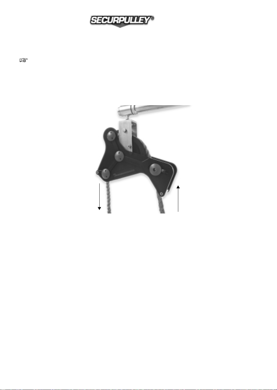
For the use of SECURPULLEY® two operators must always be employed: one at
ground and one at the working level
The load to be handled must be connected to the rope on the side where the
counterweight is arranged
The manoeuvring rope is thus the one on the opposite side (see Figure)
Figure 1a:position of manoeuvre and hoisting rope falls
The force exerted by the operator on the rope for hoisting or retaining the load involves a
push on the reeving roller 6that in turns involves a rotation of the side plates and the
opening of the brake.
Closing of the brake: the wedge-brake is in contact, with its upper surface, with a bush,
assembled on an axle, which involves the self-locking action of the lower part of the wedge
onto the rope.
This happens whenever the operator’s force on the rope ceases and the two side plate
rotate, putting the wedge in contact, at one side with the bush and at the opposite side with
the rope.
Two bushes are supplied, having different dimensions, suitable, respectively for 18 mm dia
and 20 mm dia ropes.
MANOEUVRING SIDE
LOAD SIDE

The settable counterweight 8has the function of adapt the sheave configuration to the
various heights, through a compensation of the rope weight, which changes a function
of its length.
Thanks to this regulation the braking action can always be set to the best conditions that
means to be as quick as possible in case of load fall, thus preventing dangerous ways in free
motion that involve a reduced safety and excessive dynamic efforts on the assembly at the
braking phase.
N° 4 regulation positions are foreseen for the counterweight, related to the working height
and to the rope diameter.
The table shows the suggested settings for the counterweight, according to the tests results.
The specified conditions could not be the best ones when operating with wet rope, or with
a rope having different density: always proceed to a functional test before the use.
INDICATIVE TABLE FOR THE SETTING OF THE COUNTERWEIGHT
HEIGHT (m) COUNTERWEIGHT POSITION
ROPE DIA 18 ROPE DIA 20
Up to 10 1 1
from 10 to 20 1,2 2,3
from 20 to 30 2,3 3,4
from 30 to 40 3,4
(*) limit conditions: operate with care
INSTRUCTION MANUAL FOR SAFETY SHEAVE
pag. 6
by TORNOMECCANICA s.r.l.
5. INSTRUCTIONS OF INSTALLATION AT THE WORKING PLACE
The support for SECURPULLEY® must be a standard pipe for scaffolds, with external
diameter 48 mm.
The supporting pipe must be arranged horizontally; the supporting sleeve for
SECURPULLEY® must be positioned at the free extremity of the pipe, coupled to the
pipe and locked against the longitudinal movement.
N° 3 types of supports are foreseen for SECURPULLEY®, all of them made from a pipe
with diameter 48 mm:
a) piece of standard scaffolds pipe: connection to the vertical pipe by a scaffolds clamp
preferably of pressed type of thickness adequate to insure a good stiffness.
The sleeve for SECURPULLEYÆ is fixed at the extremity of the pipe and locked against
the longitudinal movements by two clamps, one per side of SECURPULLEYÆ
b) supporting pipe for SECURPULLEY® manufactured by TORNOMECCANICA:
includes a strong clamp for the connection to the scaffolding pipe, and a locking
system at one extremity, for quick locking and unlocking of SECURPULLEY® .
The connection of SECURPULLEY® by a cantilever pipe involves a bending stress in
the clamp and in the supporting pipes: with heavy loads in free fall, the braking efforts
can make such stresses become considerable.
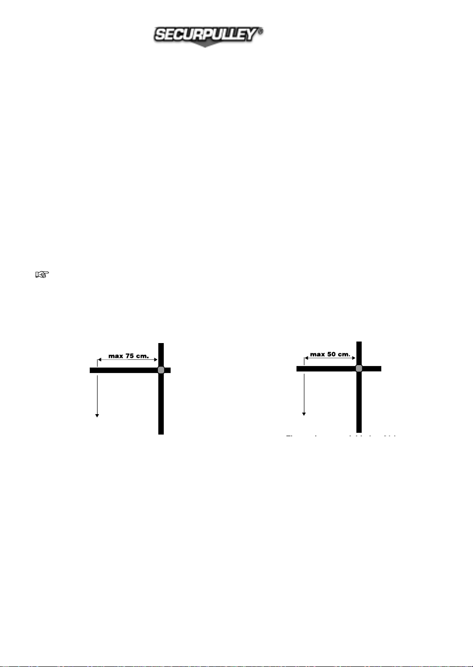
Do not overcome the cantilever dimensions indicated by figure 2,
not to charge excessively the supports
Frequently check the tightening of the clamp screws
Figure 2: cantilever support for per SECURPULLEY®
c) slewing support manufactured by TORNOMECCANICA.
The TORNOMECCANICA made slewing support, with quick slewing lock is a accessory
which includes the locking device for the SECURPULLEY? sleeve (see page9): it is made
from aluminium alloy, and therefore is particularly light.
The reinforced frame ensures a high rigidity under any load condition, and the
connection to the scaffolding pipe in N° 2 points eliminates the bending stresses on the
clamps and reduces quite a lot the efforts on them.
The slewing of the support allows to work at the working floor in an easier, qicker and safer
way, because the hanging loads can be rotated from/to the working floor together with the
whole support and SECURPULLEY®.
INSTRUCTION MANUAL FOR SAFETY SHEAVE
pag. 7
by TORNOMECCANICA s.r.l.
Fixing scheme for loads over 30 kg
Fixing scheme for loads up to 30 kg
Assembling instructions:
With every type of support, before assembling the sleeve onto the pipe, clean the two
mating surfaces and slightly grease the pipe, in order to prevent rusting (for steel pipes) and
allow the free movement between sleeve and pipe.
Assemble the support at an height of 160 - 190 cm from the working floor, for the
best working conditions of the operator who must receive the loads and make the rope
descent to ground.
Before starting operating with SECURPULLEY® check that the supporting pipe is
correctly installed and the scaffold on which the support is fixed is strong and stiff
enough.
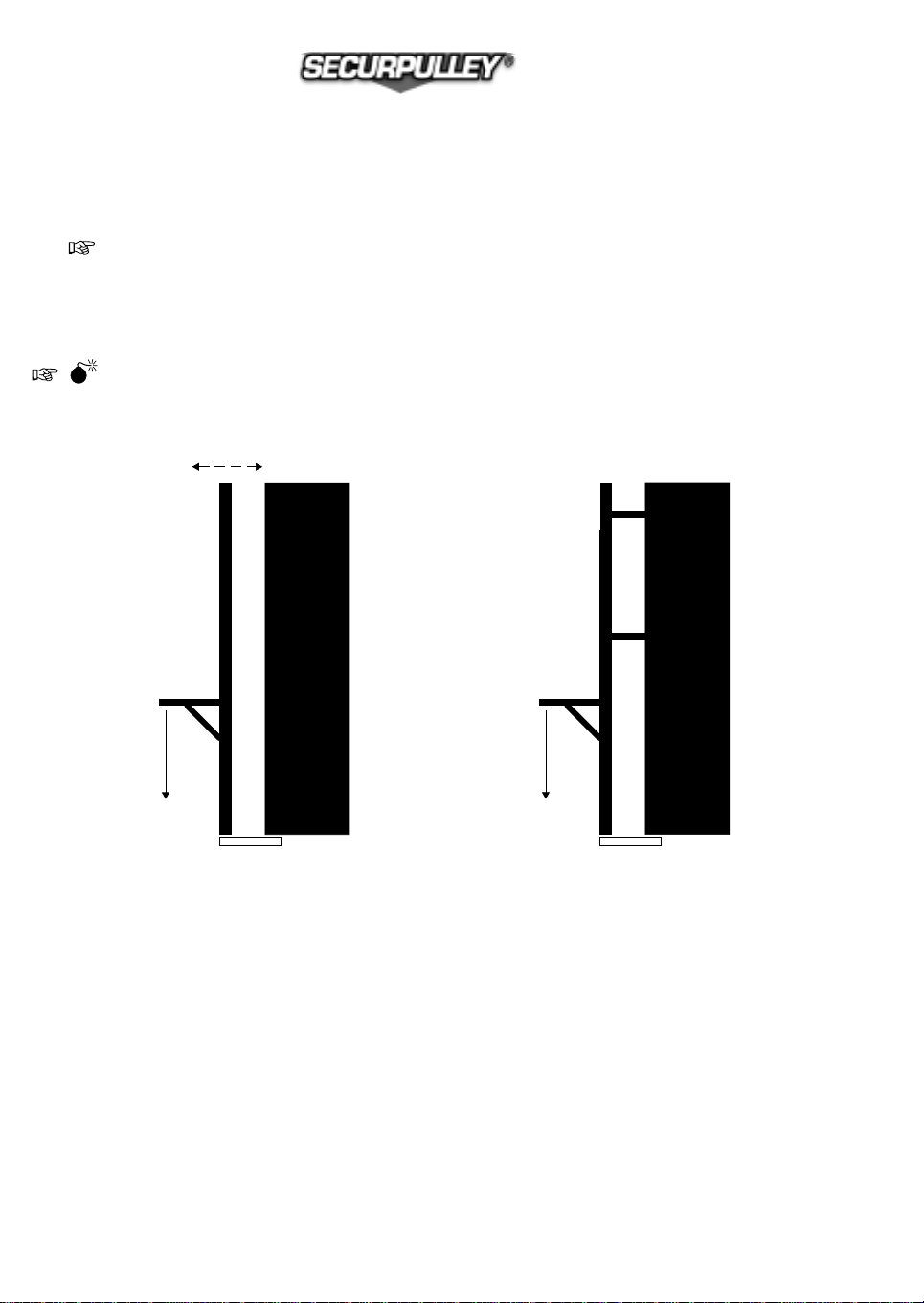
Figure 3: scheme of correct and incorrect arrangements for the support
of SECURPULLEY®
INSTRUCTION MANUAL FOR SAFETY SHEAVE
pag. 8
by TORNOMECCANICA s.r.l.
A) The pipe on which he support for
SECURPULLEY is fixed, is free at
the top, and can swing, causing an
incorrect functioning of the sheave:
incorrect arrangement
B) The pipe on which he support
for SECURPULLEY is fixed, is
stiffened by a correct connection to
the wall and cannot swing: correct
arrangement for the sheave
functioning
NO! YES!

6. INSTRUCTIONS FOR USE
6.1 Generals
SECURPULLEY® has been designed with the specific purpose of eliminating the risks
due to manual handling of parts of scaffolds, and moreover to allow the operators to
temporary stop the lifting, for rest, of for a sudden inconvenience, leaving the load
safely hanging
For the best and safe functioning, it is necessary that the setting of the balancing
counterweight is corresponding to the actual operating conditions, as previously
described.
Always lift loads adequate to the physical capacity of the operator, also related to the
lifting height
Put the due attention to the fastening of the load onto the rope:
danger of load fall
For the best safety of the operator at ground, he must stand, during the loads
handling, as far as possible from the vertical below the suspension point, in a
compatible way with the manoeuvre angle of the rope and the available space around
the scaffolding.
INSTRUCTION MANUAL FOR SAFETY SHEAVE
pag. 9
by TORNOMECCANICA s.r.l.
6.2 Insertion of the rope into the sheave
For inserting the rope into SECURPULLEY? refer to figure 4
Figure 4: insertion of the rope
Make the side plates rotate such in a way to space out the brake from the sheave.
Keep the wedge lifted, pulling downwards its rear part (not serrated)
Insert the rope in the sheave, according to figure 4: the rope must pass between the pulley
and the counterweight at the ìload sideî and over the roller at the ìpulling ropeî side.
The rope could be inserted from both sides of the sheave, but usually a knot is foreseen on it
(for locking purposes during the lowering of the empty rope) on the load lifting side. In this
case, the rope must be inserted from the counterweight side.
INSTRUCTION MANUAL FOR SAFETY SHEAVE
pag. 10
by TORNOMECCANICA s.r.l.

6.3 Regulation of the counterweight according to the lifting height
Before starting each working shift, it is compulsory to check the balancing
of the counterweight according to the working height. Move the
counterweight in the position indicated at para.4.2, and marked in the
side plate of SECURPULLEY® in correspondence with the slotted housings.
To move the counterweight proceed as follows:
— Insert the plastic key with n∞three pins in the three holes existing in one of the two
knobs located at the sides of the counterweight, at the external of the two side plates
— Keep with one hand the key and with the other hand the opposite knob
— Rotate counterclockwise until the unlocking of the counterweight is achieved, and it
can slide along the side plates
— Position the counterweight in the selected position (see table at para. 4.2)
— Tighten again the counterweight in the housing, with reverse operation of before.
Do not excessively tighten the knobs!
— Pull out the key from the knob.
INSTRUCTION MANUAL FOR SAFETY SHEAVE
pag. 11
by TORNOMECCANICA s.r.l.

6.4 Check of the wedge-pressing bush for adapting to the rope diameter
SECURPULLEY® is factory assembled with a bush suitable for rope diameter 18 mm
and marked with the 18 mm mark.
For use with a rope of 20 mm diameter the bush must be substituted with the other
one supplied with the sheave and marked with the 20 mm mark.
For substitute the bush do as follows:
For substitute the bush do as follows:
— by two 17 mm spanners unscrew the nut from the screw that keeps the
bush in place
— take off the screw and make free the bush, the bronze bush on which the
bush is assembled and the two side spacers.
— insert the new wedge-pressing bush onto the bronze bush and assemble it
on the screw with the two spacers.
— Pay attention to the position of the wedge that must have its flat part below
the wedge-pressing bush
— Tighten the nut
INSTRUCTION MANUAL FOR SAFETY SHEAVE
pag. 12
by TORNOMECCANICA s.r.l.

6.5 Functional test before use
Before starting any working shift it is compulsory to check the brake
efficiency, as herein described
After the settings described at para. 6.1.1 e 6.1.2, check the functioning as follows:
lift a little from ground a load equal to the maximum load to handle during the shift.
Release the rope and check the brake closing, which must quickly stop the load.
If the braking action is not quick, check the sheave
as described in chapter 7 before start working.
Make also the following functional checks:
• Check the free rotation of the sleeve onto the pipe
• Check the free rotation of the sheave
• Check the free rotation of the reeving roller
• Check the free movement of the two side plates
• Check the free rotation of the supporting bracket onto the sleeve
• Check the free rotation of the wedge-pressing bush
The directions for the following operations are herein given:
• Lifting of loads
• Lowering of the empty rope
• Lifting of the empty rope
• Lowering of loads
INSTRUCTION MANUAL FOR SAFETY SHEAVE
pag. 13
by TORNOMECCANICA s.r.l.

INSTRUCTION MANUAL FOR SAFETY SHEAVE
pag. 14
by TORNOMECCANICA s.r.l.
6.6 Lifting of loads (building of scaffolds)
For scaffolds erection the sequence is:
loads lifting – empty rope lowering.
Remind that SECURPULLEY• must be oriented, for a good functioning, at a right angle
to the supporting pipe during lifting and lowering of loads.
Figure 4: scheme in plant of SECURPULLEY®
orienting for loads handling
After the routine checks described at para. 3.1, firmly secure the load to lift and start pulling
the rope lifting the load towards the desired level.
As the force on the rope is decreased, as well suddenly released, the loads starts a small
descent and immediately afterwards the brake is automatically engaged and locks the rope.
The brake is operated also when the rope is taken away from the vertical, such in a way that
the lifting rope becomes inclined and the action of the rope onto the reeving roller is less
and less effective.
If the operator wants to stop the load for rest during the lifting stroke it is sufficient that he
decreases the lifting force, until the load starts come down: after a few operations it will
become easy to understand the response of SECURPULLEY® to the manoeuvres on the rope!
ROPE
SECURPULLEY®
SUPPORTING PIPE
WORKING FLOOR

When the load reaches the working level, it shall be stopped with the action before
described, and the operator at the floor will handle it to the floor. If you are working
with a rotating support TORNOMECCANICA, the operator at the floor first unlock the
rotation, than makes it rotate towards him thus taking the load towards the landing
surface.
He then takes the load and pulls the rope slightly and progressively towards him, thus
unlocking the brake: the loads will come down to the floor.
Pay attention not to make the load to descent suddenly: danger of feet
crushing!
The operator at the floor, after having the load resting down, makes the rope becoming
a little slack, unties the load and the provides the rope to go down for the next load.
INSTRUCTION MANUAL FOR SAFETY SHEAVE
pag. 15
by TORNOMECCANICA s.r.l.
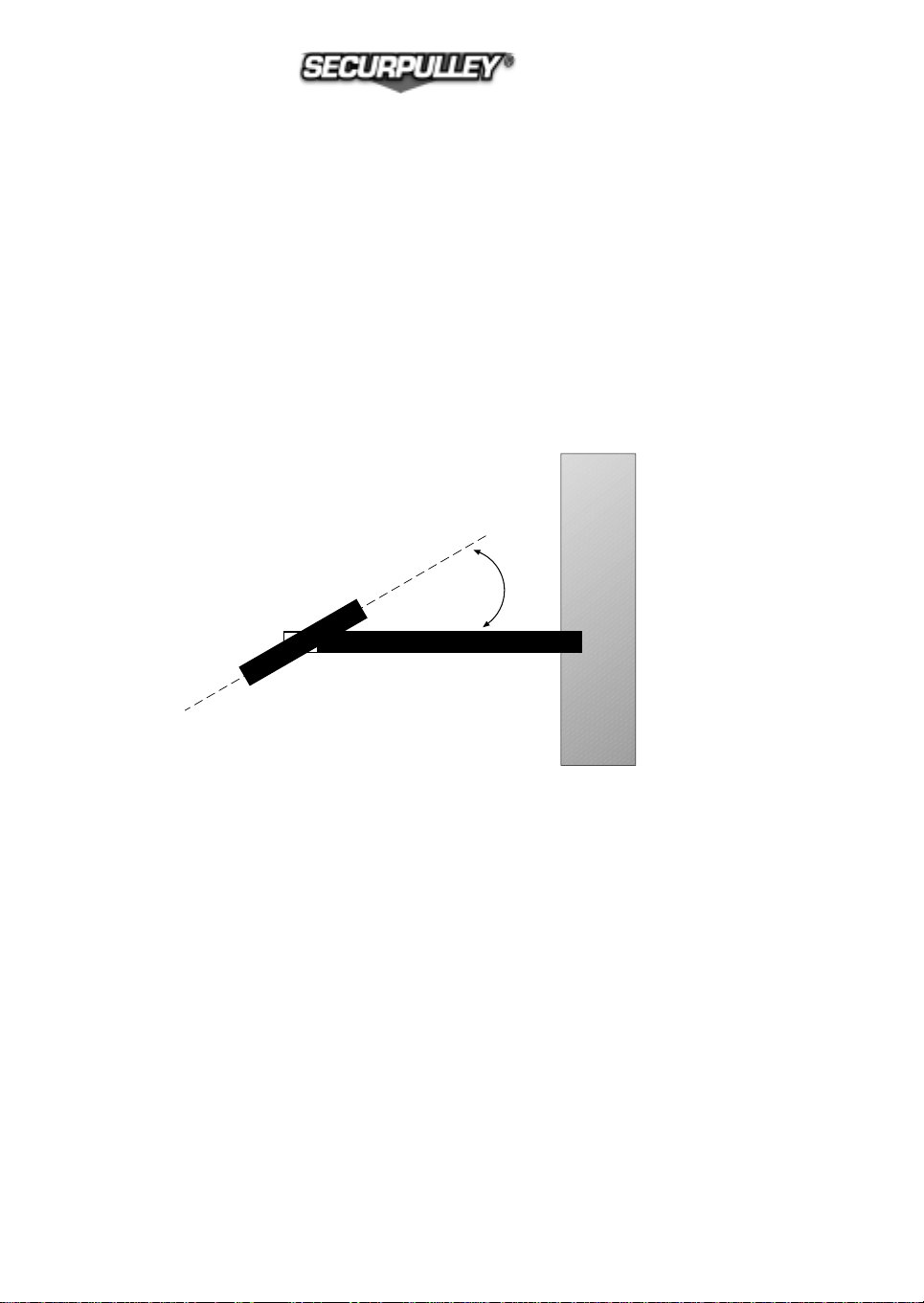
6.7 Descent to ground of the empty rope
If you are working with a rotating support TORNOMECCANICA, the operator at the
floor pulls it out and locks the support, in order to make easier the descent of the
rope, avoiding that it can entangle.
The operator at the floor pulls the rope ñ at the ìloadî(counterweight) side towards him,
orienting SECURPULLEY® at an angle of about 30° with the supporting pipe.
During this pulling action, the rope comes in contact with the counterweight spacer
and the brake is released.
In this way the ropes comes to ground. As the length and thus the weight of the rope
fall going down increases, the descent of the rope becomes easier and quicker.
Figure 5: scheme in plant of SECURPULLEY®
orienting for the descent of the empty rope.
INSTRUCTION MANUAL FOR SAFETY SHEAVE
pag. 16
by TORNOMECCANICA s.r.l.
30°

6.8 Lifting of the empty rope to the floor (scaffolds dismantling)
For scaffolds dismantling the sequence is:
empty rope lifting ñ loads lowering.
The operator at ground pulls the empty rope, that, with its dead weight keeps the brake
open.
The operator at the floor controls the rope lifting, to avoid that, over a certain height, it
increases its speed and hits the SECURPULLEY® body.
To avoid damages to SECURPULLEY® in the case the rope slips, a rubber ring
is supplied with SECURPULLEY® , to be assembled on the rope at the end used
for the load fastening.
6.9 Lowering of loads
SECURPULLEY® is gifted with a safety brake, against the loads fall, and
not to be used as a friction brake: do not use the brake for slow-down of
loads, or the rope and the brake itself will be damaged
The operator at the floor fastens the load to be lowered; the operator at ground slightly pulls
the rope and lifts the load. The brake will keep the load steady.
The operator at the floor in the meanwhile helps the load to be pulled out.
If you are working with a rotating support TORNOMECCANICA, the operator at the floor
rotates the support outwards and locks it.
The lowering can start: the operator at ground make the load go down with a continuous con-
trol of the speed.
The load must go down at a reasonable speed: an excessive speed can
involve dangers for the operator himself and other people.
In the case the rope should slip from the operator, and the load starts to go down in free
motion, the safety brake immediately stops it.
INSTRUCTION MANUAL FOR SAFETY SHEAVE
pag. 17
by TORNOMECCANICA s.r.l.
Table of contents


