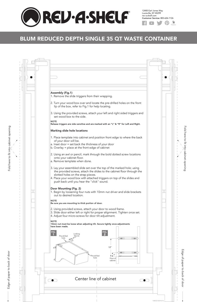
CraftBilt Materials RETRACTABLE PLEATED SCREENST User manual

!
!
Please read the instructions thoroughly before installing your new screen
system.
RETRACTABLE PLEATED SCREEN
ST - STANDARD MODEL
INSIDE MOUNT INSTALLATION

!
!
! ! Revised:!March-11-16!
!! 2!
Description Drawing Reference
Top Track A
Jamb Profile B
Pull-Bar C
Base-Jamb Mount D
Screen Cartridge E
Anchor Plate F
Bottom Guide G
Fixed Handle H
Collapsible Handle I
Dual-Central Stop (Dual-Central
Screen Systems) J
3/8" Teks Screws: Robertson #1 K
Jamb Lock (Optional) L
Required Tools and Materials Parts List
üScrewdriver and screw bits:
- Phillips #1 & #2
-Robertson #1
üScrew gun and drill
üCarpenters level or laser level
üStraight edge
üPencil
üCleaning cloth
üDegreaser or alcohol based cleaner
üHand saw or chop saw
üAnchoring screws for top track, base-jamb
mount and anchor plates (16-20 screws)
üDrill bit to pre-drill holes for anchoring screws
üPlywood or similar:
-Thickness: 1/2” or 3/4” (13mm-19mm)
-Width: 1-3/4” (45mm)
-Height: 6” (152mm)
Screen Diagram

!
!
! ! Revised:!March-11-16!
!! 3!
Installation
1. Ensure the Installation location is level and clean
2. Install the Top Track to the Header -
Part: A
üFasten the top track to the header using screws that best fit the application
ü
Note: Pre-drill the top track before fastening the top track to the header
ü
Note: Make sure the top track is positioned where you would like your retractable screen to operate - plumb
the top track with the bottom surface where your bottom guide will be positioned
3. Dual Central Screen Configurations
ONLY
-
Parts: J and K
üIf you have ordered a dual-central screen configuration, you will be required to install a dual-central stop in
the center of the top track
üFind the center of the top track and mark it with a pencil
üFasten the D/C stop to the top track with the provided TEK screws -
Part: K
ü
Note: Use the centerline in the top track as a guide when installing the D/C stop
4. Install the Jamb Profile -
Part: B
üFind the center of the top track by measuring 7/8” (23mm) from either side of top track
üUse a straight edge or a laser to inscribe a line down the vertical surface
üPeel the backing off of the anchor plates for temporary positioning
üAlign the center of the anchor plates with the inscribed line
ü
Note: Ensure that the anchor plates are evenly spaced
üFasten the anchor plates to the inside surface with fasteners that best fit the application
üJamb Lock Option: Insert jamb lock into the jamb profile by sliding the metal plate on the rear of the jamb
lock into the center groove on the jamb profile -
Part: L
üInsert the top of the jamb profile into the top track and then push the jamb profile into the anchor plates
ü
Note: The jamb can be fastened to either vertical inside surface depending on which direction you want the
screen to operate
- Left to Right: Install jamb profile on right side
- Right to Left: Install jamb profile on left side
ü
Note: The jamb profile can be directly fastened to the inside surface with fasteners if required
5. Install the Base Jamb Mount -
Part: D
üInstall the base-jamb mount on the vertical surface opposite of the jamb profile that was installed in Step #4
üPre-drill the base-jamb mount every 2 feet (610mm)
üThe top of the base-jamb mount inside the top track and align the bottom of the jamb mount so that it’s level
and square
üFasten the base-jamb mount to the vertical surface with fasteners that best fit the application

!
!
! ! Revised:!March-11-16!
!! 4!
6. Install the Bottom Guide -
Part: G
üClean the bottom surface using a degreaser or alcohol based cleaner
üAlign the bottom guide with the anchor plates, jamb profile and top track
üTemporarily position the bottom guide to ensure proper fitment, the bottom guide should fit under the
magnet located in the jamb profile
ü
Note: Do not place the bottom guide underneath the jamb profile
ü
Note: The bottom guide may require additional cutting to fit the application
ü
Note: When connecting two lengths of the bottom guide connect the ends marked with a red line
üOnce the bottom guide has been positioned, peel the backing off of the guide and press down on the bottom
guide to ensure a secure bond
ü
Note: The bottom guide may not fully adhere in cold weather applications. It is recommended that the
bottom guide adhesive is at room temperature before installation and that the bottom surface is clean and
dry. In addition, the bottom guide can always be fastened to the bottom surface with a countersunk, flat
head screw.
7. Install the Screen Cartridge -
Part: E
üCut a piece of plywood or similar wood product to the following dimensions: 1-3/4” (45mm) wide x 6”
(152mm) long
üUse the piece of wood to spread the top track, while inserting the pull-bar retainer into the top track
üLine up the pull-bar retainer besides the wooden spreader and insert the top of the screen cartridge into the
top track
üNote: be carefully not to bend the steel band when inserting the screen cartridge into the top track
üRemove the wood spreader from the top track
üAlign the bottom of the screen cartridge with the bottom guide
üSnap the ST base jamb profile into the “base-jamb mount ” by applying moderate horizontal force to the
screen cartridge
8. Install Handles -
Parts: H and I
üFind the knob on the rear of the handle
üInsert the knob into the groove in the pull-bar (
Part: C
) at 90 degrees
üAdjust the handle to your desired height and turn the handle counter-clockwise until it snaps into place
9. Adjust the Jamb Lock -
*Optional - Part: L
üExtend your screen system so that the pull-bar engages the jamb lock. If the jamb lock does not fully engage,
please perform the following steps:
üRetract your screen system
üPull the handle on the jamb lock upwards, while holding the base of the jamb lock in place
üUse a #1 Phillips screwdriver to turn the mounting screw 1/2 turn, counter-clockwise
üAdjust the jamb lock up and down so that the jamb lock fully engages the pull-bar in the locked position.
üAfter the height has been adjusted, tighten the mounting screw on the jamb lock
10. After installing your screen system, repetitively extend and retract the screen to ensure a smooth operation. If
you experience any one of the following problems, please refer to the trouble-shooting guide:
üThe pull-bar does not completely close to the jamb
üThe screen does not completely retract
üThe screen does not operate smoothly

!
!
! ! Revised:!March-11-2016!5!
Troubleshooting
I have successfully installed my new Craft-Bilt pleated screen, but the screen does not fully
extend?
Occasionally during the shipping process the strings in the screen cartridge can become tangled. To un-tangle the
wires, repetitively extend and retract the screen system until the screen fully extends. When retracting the screen
system, use enough force to pull the wires free, but not to the point where the screen cartridge detaches from the
base jamb mount.
The chain on the bottom of the screen has come off of the bottom guide?
The screen system is designed to allow the chain to come off of the bottom guide when a person, object or animal
unintentionally hits the screen. If this situation occurs, simply place the chain back on the bottom guide.
My Craft-Bilt pleated screen takes an unusually large amount of force to extend and retract, and
is not running smoothly
1) If the tensioning strings going across the mesh are too tight, the screen will run rough and require an
unusually large amount of force to move the pull-bar. See the adjustment instructions in the User’s Manual
to adjust the wire tension for your specific screen model.
2) Check the plastic chain that runs on the bottom of the screen for any debris. Use a vacuum cleaner, water
hose and/or cloth to clean any debris out of the chain.
My Craft-Bilt pleated screen does not fully retract?
If your screen does not fully retract, the horizontal tensioning strings are too loose. The more tension you put on
the strings, the better the pull-bar will fully retract.
Caution: If you put too much tension on the strings the screen will not operate smoothly. See the adjustment
instructions in the User’s Manual to adjust the string tension for your specific screen model.
My Craft-Bilt pleated screen does not extend parallel to the jamb profile.
See the adjustment instructions in the User’s Manual to adjust the parallelism for your particular screen model.
The height of my opening has increased/decreased. Will my Craft-Bilt pleated screen still
operate?
Each screen system can tolerate a height fluctuation of 1/4” (6mm) downwards and 1/2” (14mm) upwards. If your
rough opening is out more then these tolerances, your screen system will not operate safely.
The width of the top track is more then the width of my opening?
If the top track is wider then your opening you will be required to cut the top track and bottom guide. Use a chop
saw or handsaw to cut top track and bottom guide to the correct width. The top track will equal the total width of
the rough opening. The bottom guide will equal the total width of the rough opening less 3/4” (20mm).
Note: Every Craft-Bilt pleated screen is manufactured to close 1/2” (12.7mm) past the total width of your opening.
!
!
Table of contents
