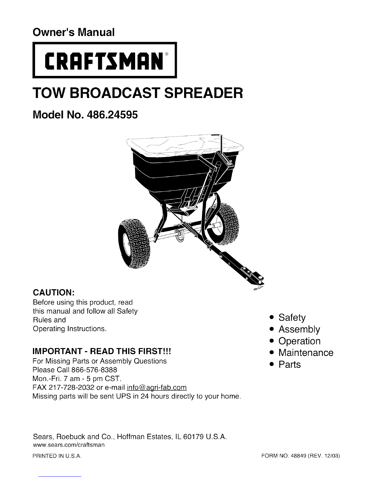
Craftsman 486.24595 User manual
Other Craftsman Spreader manuals

Craftsman
Craftsman 486.243222 User manual

Craftsman
Craftsman 486.24321 User manual

Craftsman
Craftsman 486.24494 User manual

Craftsman
Craftsman 486.24331 User manual

Craftsman
Craftsman 486.243234 User manual

Craftsman
Craftsman 486.245941 User manual

Craftsman
Craftsman 486.24321 User manual

Craftsman
Craftsman 486.1994 User manual

Craftsman
Craftsman 486.24352 User manual

Craftsman
Craftsman 486.24009 User manual

Craftsman
Craftsman 486.243223 User manual

Craftsman
Craftsman 486.243231 User manual

Craftsman
Craftsman 486.245951 User manual

Craftsman
Craftsman 486.243232 User manual

Craftsman
Craftsman 486.243223 User manual

Craftsman
Craftsman 24594 - Professional Universal Broadcast... User manual

Craftsman
Craftsman 486.24393 User manual

Craftsman
Craftsman 486.24331 User manual

Craftsman
Craftsman 486.24009 User manual

Craftsman
Craftsman CMXGZBF450532DL User manual


Popular Spreader manuals by other brands


Fisher
Fisher POLY-CASTER 78601 owner's manual

TurfEx
TurfEx RS7200 Owner's/operator's manual

Fayat Group
Fayat Group DYNAPAC S100 operation & maintenance

Art's-Way Manufacturing
Art's-Way Manufacturing X700 Operator's manual & parts list

Ferris
Ferris Pathfinder Series Operator's manual

EASTMAN
EASTMAN CR 500 instruction manual