manuals.online logo
Brands
  1. Home
  2. •
  3. Brands
  4. •
  5. Craftsman
  6. •
  7. Tiller
  8. •
  9. Craftsman 917.299082 User manual

Craftsman 917.299082 User manual

Other Craftsman Tiller manuals

Craftsman 536.7975 User manual

Craftsman

Craftsman 536.7975 User manual

Craftsman 944.629663 User manual

Craftsman

Craftsman 944.629663 User manual

Craftsman 917.291491 User manual

Craftsman

Craftsman 917.291491 User manual

Craftsman 917.293301 User manual

Craftsman

Craftsman 917.293301 User manual

Craftsman 917.297020 User manual

Craftsman

Craftsman 917.297020 User manual

Craftsman 917.298231 User manual

Craftsman

Craftsman 917.298231 User manual

Craftsman 486.252444 User manual

Craftsman

Craftsman 486.252444 User manual

Craftsman TILLER 917.292394 User manual

Craftsman

Craftsman TILLER 917.292394 User manual

Craftsman 917.295852 User manual

Craftsman

Craftsman 917.295852 User manual

Craftsman 247.29934 User manual

Craftsman

Craftsman 247.29934 User manual

Craftsman 3.75 HP 17 INCH TINE WIDTH 917.2922 User manual

Craftsman

Craftsman 3.75 HP 17 INCH TINE WIDTH 917.2922 User manual

Craftsman 944.629673 User manual

Craftsman

Craftsman 944.629673 User manual

Craftsman 917.291490 User manual

Craftsman

Craftsman 917.291490 User manual

Craftsman Incredi-Pull 316.292640 User manual

Craftsman

Craftsman Incredi-Pull 316.292640 User manual

Craftsman CRAFTSMAN 757.243481 User manual

Craftsman

Craftsman CRAFTSMAN 757.243481 User manual

Craftsman 29358 User manual

Craftsman

Craftsman 29358 User manual

Craftsman 917.297110 User manual

Craftsman

Craftsman 917.297110 User manual

Craftsman 316.292701 User manual

Craftsman

Craftsman 316.292701 User manual

Craftsman 486.24338 User manual

Craftsman

Craftsman 486.24338 User manual

Craftsman 917.293470 User manual

Craftsman

Craftsman 917.293470 User manual

Craftsman 247.29932 User manual

Craftsman

Craftsman 247.29932 User manual

Craftsman 917.299210 User manual

Craftsman

Craftsman 917.299210 User manual

Craftsman 917.297350 User manual

Craftsman

Craftsman 917.297350 User manual

Craftsman 247.29932 User manual

Craftsman

Craftsman 247.29932 User manual

Popular Tiller manuals by other brands

WIL-RICH 2500 Operator's manual

WIL-RICH

WIL-RICH 2500 Operator's manual

MTD 410R parts list

MTD

MTD 410R parts list

Viking HB 685 instruction manual

Viking

Viking HB 685 instruction manual

SMASH TLG415 instruction manual

SMASH

SMASH TLG415 instruction manual

FarmBoy FB-IC-209P user manual

FarmBoy

FarmBoy FB-IC-209P user manual

MTD FRT Series Operator's manual

MTD

MTD FRT Series Operator's manual

Troy-Bilt Colt FT Operator's manual

Troy-Bilt

Troy-Bilt Colt FT Operator's manual

MTD OHV Series Original operating instructions

MTD

MTD OHV Series Original operating instructions

YAT YT5601-01 Assembly, Use, Maintenance Manual

YAT

YAT YT5601-01 Assembly, Use, Maintenance Manual

Scheppach MTP560 Translation from the original instruction manual

Scheppach

Scheppach MTP560 Translation from the original instruction manual

GARDEN WAY 12194 owner's manual

GARDEN WAY

GARDEN WAY 12194 owner's manual

Classen STAND-AER SA-25 Operator's manual and parts list

Classen

Classen STAND-AER SA-25 Operator's manual and parts list

Altrad ATIKA BH 1400 N Original instructions, safety instructions, spare parts

Altrad

Altrad ATIKA BH 1400 N Original instructions, safety instructions, spare parts

DR PILOT 2 Safety & Operating Instructions

DR

DR PILOT 2 Safety & Operating Instructions

AL-KO TL 1820 Instructions for use

AL-KO

AL-KO TL 1820 Instructions for use

breviglieri mekfarmer 120 Operating and maintenance

breviglieri

breviglieri mekfarmer 120 Operating and maintenance

Troy-Bilt 769-03618 Operator's manual

Troy-Bilt

Troy-Bilt 769-03618 Operator's manual

SNOWJOE SUNJOE TJ602E-RM Operator's manual

SNOWJOE

SNOWJOE SUNJOE TJ602E-RM Operator's manual

manuals.online logo
manuals.online logoBrands
  • About & Mission
  • Contact us
  • Privacy Policy
  • Terms and Conditions

Copyright 2025 Manuals.Online. All Rights Reserved.

Owner's Manual BN°
TI
UAL
900 Series
17
ETLL
OTATI
Inch Tine Width
TI iT
ES
Model No.
917.299082
•EspaSol, p. 23
This product has a low emission engine which operates
differently from previously built engines. Before you start the
engine, read and understand this Owner's Manual.
IMPORTANT:
Read and follow all Safety
Rules and Instructions before
operating this equipment.
Sears, Roebuck and Co., Hoffman Estates, IL 60179
Visit our Craftsman website:www.sears.com/craftsman
U.S.A.
428622 Rev 1
Warranty ................................................ 2
Safety Rules .......................................... 2
Product Specifications ......................... 4
Assembly/Pre-Operation ....................... 6
Operation ............................................... 8
Maintenance Schedule ........................ 14
Maintenance ....................................... 14
Service and Adjustments ..................... 16
Storage ................................................ 20
Troubleshooting ................................... 21
Illustrated Parts List ............................. 44
Sears Service ........................ Back Cover
LIMITED TWO YEAR WARRANTY ON CRAFTSMAN TILLER
For two (2) years from date of purchase, when this Craftsman Tiller is maintained,
lubricated, and tuned up according to the operating and maintenance instructions in the
owner's manual, Sears will repair free of charge any defect in material or workmanship.
This Warranty does not cover:
• Expendable items which become worn during normal use, such as tines, spark plugs,
air cleaners and belts.
• Repairs necessary because of operator abuse or negligence, including bent crank-
shafts and the failure to maintain the equipment according to the instructions con-
tained in the owner's manual.
• If this Craftsman Tiller is used for commercial or rental purposes, this Warranty applies
for only thirty (30) days from the date of purchase.
Warranty service is available by returning the craftsman power mower to the nearest
sears service center/department in the united states. This warranty applies only while
this product is in use in the united states.
This Warranty gives you specific legal rights, and you may also have other rights which
vary from state to state.
SEARS, ROEBUCKAND CO., D/817WA, HOFFMAN ESTATES, IL 60179 U.S.A.
IMPORTANT: This cutting machine is capable of amputating hands and feet and throw-
ing objects. Failure to observe the following safety instructions could result in serious
injury or death.
TRAINING
• Read the Owner's Manual carefully. Be
thoroughly familiar with the controls and
the proper use of the equipment. Know
how to stop the unit and disengage the
controls quickly.
• Never allow children to operate the
equipment. Never allow adults to op-
erate the equipment without proper
instruction.
• Keep the area of operation clear of all
persons, particularly small children, and
pets.
PREPARATION
• Thoroughly inspect the area where the
equipment is to be used and remove all
foreign objects.
• Disengage all clutches and shift into
neutral before starting the engine (mo-
tor).
• Do not operate the equipment without
wearing adequate outer garments. Wear
footwear that will improve footing on
slippery surfaces.
• Handle fuel with care; it is highly flam-
mable.
• Use an approved fuel container.
• Never add fuel to a running engine or
hot engine.
• Fill fuel tank outdoors with extreme care.
Never fill fuel tank indoors.
• Replace gasoline cap securely and
clean up spilled fuel before restarting.
2
• Use extension cords and receptacles
as specified by the manufacturer for all
units with electric drive motors or elec-
tric starting motors.
• Never attempt to make any adjustments
while the engine (motor) is running (ex-
cept where specifically recommended
by manufacturer).
OPERATION
• Do not put hands or feet near or under
rotating parts.
• Exercise extreme caution when operat-
ing on or crossing gravel drives, walks,
or roads. Stay alert for hidden hazards
or traffic. Do not carry passengers.
• After striking a foreign object, stop the
engine (motor), remove the wire from
the spark plug, thoroughly inspect the
tiller for any damage, and repair the
damage before restarting and operating
the tiller.
• Exercise caution to avoid slipping or fall-
ing.
• If the unit should start to vibrate ab-
normally, stop the engine (motor) and
check immediately for the cause. Vibra-
tion is generally a warning of trouble.
• Stop the engine (motor) when leaving
the operating position.
• Take all possible precautions when leav-
ing the machine unattended. Disengage
the tines, shift into neutral, and stop the
engine.
• Before cleaning, repairing, or inspecting,
shut off the engine and make certain all
moving parts have stopped. Disconnect
the spark plug wire, and keep the wire
away from the plug to prevent accidental
starting. Disconnect the cord on electric
motors.
• Do not run the engine indoors; exhaust
fumes are dangerous.
• Never operate the tiller without proper
guards, plates, or other safety protective
devices in place.
• Keep children and pets away.
• Do not overload the machine capacity
by attempting to till too deep at too fast
a rate.
• Never operate the machine at high
speeds on slippery surfaces. Look be-
hind and use care when backing.
• Never allow bystanders near the unit.
• Use only attachments and accessories
approved by the manufacturer of the
tiller.
• Never operate the tiller without good vis-
ibility or light.
• Be careful when tilling in hard ground.
The tines may catch in the ground and
propel the tiller forward. If this occurs,
let go of the handlebars and do not
restrain the machine.
MAINTENANCE AND STORAGE
• Keep machine, attachments, and ac-
cessories in safe working condition.
• Check shear pins, engine mounting
bolts, and other bolts at frequent inter-
vals for proper tightness to be sure the
equipment is in safe working condition.
• Never store the machine with fuel in the
fuel tank inside a building where ignition
sources are present, such as hot water
and space heaters, clothes dryers, and
the like. Allow the engine to cool before
storing in any enclosure.
• Always refer to the operator's guide
instructions for important details if the
tiller is to be stored for an extended
period.
_lkLook for this symbol to point out
important safety precautions. It means
CAUTION!!! BECOME ALERT!!! YOUR
SAFETY IS INVOLVED.
_CAUTION: Always disconnect spark
plug wire and place wire where it cannot
contact spark plug in order to prevent acci-
dental starting when setting up, transport-
ing, adjusting or making repairs.
,_WARNING: Engine exhaust, some of its
constituents, and certain vehicle compo-
nents contain or emit chemicals known to
the State of California to cause cancer and
birth defects or other reproductive harm.
3
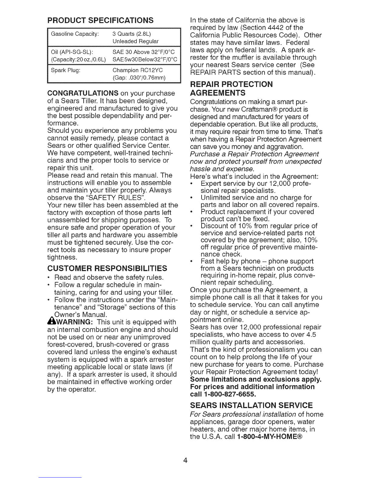
PRODUCT SPECIFICATIONS
Gasoline Capacity: 3 Quarts (2.8L)
Unleaded Regular
Oil (API-SG-SL): SAE 30 Above 32°F/0°C
(Capacity:20 oz./0.6L) SAE5w30Below32°F/0°C
Spark Plug: Champion RC12YC
(Gap: .030"/0.76mm)
CONGRATULATIONS on your purchase
of a Sears Tiller. It has been designed,
engineered and manufactured to give you
the best possible dependability and per-
formance.
Should you experience any problems you
cannot easily remedy, please contact a
Sears or other qualified Service Center.
We have competent, we!l-trained techni-
cians and the proper tools to service or
repair this unit.
Please read and retain this manual. The
instructions will enable you to assemble
and maintain your tiller properly. Always
observe the "SAFETY RULES".
Your new tiller has been assembled at the
factory with exception of those parts left
unassembled for shipping purposes. To
ensure safe and proper operation of your
tiller all parts and hardware you assemble
must be tightened securely. Use the cor-
rect tools as necessary to insure proper
tightness.
CUSTOMER RESPONSIBiLiTIES
• Read and observe the safety rules.
• Follow a regular schedule in main-
taining, caring for and using your tiller.
• Follow the instructions under the "Main-
tenance" and "Storage" sections of this
,_i_Owner's Manual.
WARNING: This unit is equipped with
an internal combustion engine and should
not be used on or near any unimproved
forest-covered, brush-covered or grass
covered land unless the engine's exhaust
system is equipped with a spark arrester
meeting applicable local or state laws (if
any). If a spark arrester is used, it should
be maintained in effective working order
by the operator.
In the state of California the above is
required by law (Section 4442 of the
California Public Resources Code). Other
states may have similar laws. Federal
laws apply on federal lands. A spark ar-
rester for the muffler is available through
your nearest Sears service center (See
REPAIR PARTS section of this manual).
REPAIR PROTECTION
AGREEMENTS
Congratulations on making a smart pur-
chase. Your new Craftsman® product is
designed and manufactured for years of
dependable operation. But like all products,
it may require repair from time to time. That's
when having a Repair Protection Agreement
can save you money and aggravation.
Purchase a Repair Protection Agreement
now and protect yourseff from unexpected
hassle and expense.
Here's what's included in the Agreement:
• Expert service by our 12,000 profe-
sional repair specialists.
• Unlimited service and no charge for
parts and labor on all covered repairs.
• Product replacement if your covered
product can't be fixed.
• Discount of 10% from regular price of
service and service-related parts not
covered by the agreement; also, 10%
off regular price of preventive mainte-
nance check.
• Fast help by phone- phone support
from a Sears technician on products
requiring in-home repair, plus conve-
nient repair scheduling.
Once you purchase the Agreement, a
simple phone call is all that it takes for you
to schedule service. You can call anytime
day or night, or schedule a service ap-
pointment online.
Sears has over 12,000 professional repair
specialists, who have access to over 4.5
million quality parts and accessories.
That's the kind of professionalism you can
count on to help prolong the life of your
new purchase for years to come. Purchase
your Repair Protection Agreement today!
Some limitations and exclusions apply.
For prices and additional information
call 1-800-827-6655.
SEARS iNSTALLATION SERVICE
For Sears professional installation of home
appliances, garage door openers, water
heaters, and other major home items, in
the U.S.A. call 1-800-4-MY-HOME®
4
These accessories were available when the tiller was purchased. They are also avail-
able at most Sears Retail outlets and Service Centers. Most Sears Stores can order
repair parts for you when you provide the model number of your tiller.
ENGINE
SPARK PLUG MUFFLER AiR FILTER GAS CAN ENGINE OiL STABiLiZER
TILLER PERFORMANCE
FURROW OPENER
TILLER MAINTENANCE
BELT TINES SHEAR PiN
O
i
:1
HAiRPiN CLIP
CONTENTS OF HARDWARE PACK
(2) Handle Locks (1) Carriage Bolt
3/8-16 UNC x 1 Gr. 5
(1) Hairpin Clips
o
(2) Shear Pins & Clips
G
(1) Center Locknut
3/8-16 UNC
(1) Cable Clip
(1) Flat Washer
13/32xlx11Ga.
0(1) Handle Lock Lever
D
(1) Pivot Bolt
3/8-16 UNC Grade 5
5
Your new tiller has been assembled at the factory with the exception of those parts left
unassembled for shipping purposes. To ensure safe and proper operation of your tiller
all parts and hardware you assemble must be tightened securely. Use the correct tools
as necessary to insure proper tightness.
TOOLS REQUIRED FOR
ASSEMBLY
A socket wrench set will make assembly
easier. Standard wrench sizes are listed.
(1) Utility knife
(1) Wire cutter
(1) Tire pressure gauge
(1) Screwdriver
(1) Pair of pliers
(1) 9/16" wrench
OPERATOR'S POSITION
When right or left hand is mentioned in
this manual, it means when you are in the
operating position (standing behind tiller
handles). FRONT
LEFT RIGHT
OPERATOR'S
POSITION
UNPACKING CARTON
_ILCAUTION: Be careful of exposed sta-
ples when handling or disposing of carton-
ing material.
IMPORTANT: When unpacking and as-
sembling tiller, be careful not to stretch or
kink cables.
1. While holding handle assembly, cut
came ties securing handle assembly to
top frame. Let handle assembly rest
on tiller.
2. Remove top frame of carton.
3. Slowly ease handle assembly up and
place on top of carton.
4. Cut down right hand front and right
hand rear corners of carton. Lay side
carton wall down.
.Remove packing material from handle
assembly.
Shift Rod
Handle
Assembly
INSTALL HANDLE
.Insert one handle lock (with teeth fac-
ing outward) in gearcase notch. (Apply
grease on smooth side of handle lock
to aid in keeping lock in place until
handle assembly is lowered into po-
sition.)
VIEWED FROM R.H. SIDE OF TILLER
Handle Assembly
Gearcase Notch
Handle Lock
2. Grasp handle assembly. Hold in "up"
position. Be sure handle lock remains
in gearcase notch. Slide handle as-
sembly into position.
"':-::":::;:i;,s;;ii:_://_ "UP"HandlePositionAssembly
': _, Tighten handle
'"'""" lock lever to hold
"%.
Loosen Handle
Lock Lever to
Move
6
3. Rotate handle assembly down. Insert
rear carriage bolt first, with head of
bolt on LH. side of tiller and loosely as-
semble Iocknut.
4. Insert pivot bolt in front part of plate
and tighten.
5. Cut down left hand rear corner of car-
ton. Lay rear carton wall down, which
will remove the protective cardboard
flap from leveling shield.
6. Cut down remaining corners of carton
and lay panels flat.
7. Lower the handle assembly. Tighten
nut on carriage bolt so handle moves
with some resistance. This will allow
for easier adjustment.
8. Place flat washer on threaded end of
handle lock lever.
9. Insert handle lock lever through handle
base and gearcase. Screw in handle
lock lever just enough to hold lever in
place.
10. Insert second handle lock (with teeth
inward) in the slot of the handle base
(just inside of washer).
11 .With handle assembly in lowest posi-
tion, securely tighten handle lock lever
by rotating clockwise. Leaving handle
assembly in lowest position will make it
easier to remove tiller from carton.
Flat Washer Handle Lock
Handle Lock Lever
N
Rear
Cartridge Slot
Bolt
Handle Base Locknut_ Pivot Bolt
INSERT CABLE CLIP
• Insert plastic cable clip into hole on the
back of handle column. Push cables
into clip.
Handle Column
\Cable
CONNECT SHIFT ROD
1. Insert end of shift rod into hole of shift
lever indicator.
2. Insert hairpin clip through hole of shift
rod to secure.
Shift Lever
Hairpin Indicator
Shift Rod
REMOVE TILLER FROM CRATE
1. Adjust handle assemby to lowest
position. Be sure lock lever is tightened
securely.
2. Make sure shift lever indicator is in "N"
(neutral) position.
3. Tilt tiller forward by lifting handle. Sep-
arate cardboard cover from leveling
shield.
4. Rotate tiller handle to the right and pull
tiller out of carton.
CHECK TIRE PRESSURE
The tires on your unit were overinflated at
the factory for shipping purposes. Correct
and equal tire pressure is important for
best tilling performance.
• Reduce tire pressure to 20 PSI.
HANDLE HEIGHT
Handle height may be adjusted to bet-
ter suit operator. (See "TO ADJUST
HANDLE HEIGHT" in the Service and
Adjustments section of this manual).
handles 101
Clip
7
These symbols may appear on your Tiller or in literature supplied with the product.
Learn and understand their meaning.
KNOW YOUR TILLER
READ THIS OWNER'S MANUAL AND SAFETY RULES BEFORE OPERATING YOUR
TILLER.
Compare the illustrations with your tiller to familiarize yourself with the location of
various controls and adjustments. Save this manual for future reference.
NO
CAUTION ENGINE ENGINE FAST SLOW CHOKE FUEL OIL
TILLING TILLING FORWARD NEUTRAL REVERSE OR WARNING ON OFF
Shift Lever
Drive Control Bar
Choke Control
Shift Lever Indicator
Throttle Control
Drag Stake
Depth Stake
Leveling Shield
Outer Side Shield
Recoil
Starter
Handle
MEETS ANSI SAFETY REQUIREMENTS
Our tillers conform to the safety standards of the American National Standards Institute.
DEPTH STAKE - Controls depth at which
tiller will dig.
DRAG STAKE - Controls forward speed in
forward rotating till position.
DRIVE CONTROL BAR - Used to engage
tines.
LEVEMNG SHIELD - Levels tilled soil.
OUTER SIDE SHIELD - Adjustable to
protect small plants from being buried.
RECOIL STARTER HANDLE - Used to
start the engine.
SHIFT LEVER - Used to shift transmission
gears.
SHIFT LEVER INDICATOR - Shows
which gear the transmission is in.
THROTTLE CONTROL - Used to control
engine speed.
8
The operation of any tiller can result in foreign objects thrown into the eyes,
which can result in severe eye damage. Always wear safety glasses or eye
shields before starting your tiller and while tilling. We recommend standard
safety glasses or a wide vision safety mask worn over spectacles.
HOW TO USE YOUR TILLER
Know how to operate all controls before
adding fuel and oil or attempting to start
engine.
STOPPING
TINES AND DRIVE
1. Release drive control bar to stop move-
ment.
2. Move shift lever to "N" (neutral) po-
sition.
ENGINE
• Move throttle control to "STOP" position.
If equipped with stop switch, move
switch to "STOP" position.
NOTE: Never use choke to stop engine.
Drive Control Bar
"ENGAGED" Shift Lever
HARD TO SHIFT GEARS
• Briefly engage drive control bar and re-
lease or rock tiller forward and backward
until are able to shift gears.
DEPTH STAKE
The depth stake can be raised or lowered
to allow you more versatile tilling and cul-
tivating, or to more easily transport your
tiller.
Shallowest Tilling
Deepest Tilling
Depth Stake ---------
DRAG STAKE
-- Transport Position
Drive Control Bar
"DISENGAGED"
Position
TINE OPERATION - WITH WHEEL
DRIVE
• Always release drive control bar before
moving shift lever into another position.
• Tine movement is achieved by moving
shift lever to either the counter rotating
(_) till position or the forward rotating
(_) till position and engaging drive con-
trol bar.
FORWARD =WHEELS ONLY/TINES
STOPPED
The drag stake should be raised when
tilling the counter rotating (_) till position.
The drag stake should be lowered when
tilling in the forward rotating (_) till posi-
tion.
Lowered
(Forward Rotating till)
Raised
(Counter rotating till)
• Release drive control bar and move shift
lever indicator to "F" (forward) position.
Engage drive control bar and tiller will
move forward,
REVERSE =WHEELS ONLY/TINES
STOPPED
1. DO NOT STAND DIRECTLY BEHIND
TILLER.
2. Release the drive control bar.
3. Move throttle control to "SLOW" po-
sition.
4. Move shift lever indicator to "R" (re-
verse) position.
5. Hold drive control bar against the
handle to start tiller movement.
TILLING
NOTE: Use the counter rotating tine drive
when tilling hard or rockey soil, virgin
ground or sod.
1. Release depth stake and drag stake
pins. Pull the depth stake up for
increased tilling depth. Raise the drag
stake. Place proper pin in hole of depth
stake or drag stake to lock in position.
2. Place shift lever indicator in counter
rotating (_) till position.
3. Hold the drive control bar against the
handle to start tilling movement. Tines
and wheels will both turn.
9
4. Move throttle control to "FAST" position
for deep tilling.
IMPORTANT: Always release drive control
bar before moving shift lever into another
position. "Locked" Position
\
Depth or Drag
Pin
Nut
"a"
Position
Outer Side
Shield
TURNING
1. Release the drive control bar.
2. Move throttle control to "SLOW" posi-
tion.
3. Place shift lever indicator in "F" (for-
ward) position. Tines will not turn.
4. Lift handle to raise tines out of ground.
5. Swing the handle in the opposite
direction you wish to turn, being careful
to keep feet and legs away from tines.
6. When you have completed your turn-
around, release the drive control bar
and lower handle. Place shift lever in
(till) position and move throttle control
to desired speed. To begin tilling, hold
drive control bar against the handle.
CULTIVATING
NOTE: Use the forward rotating tine drive
when cultivating, tilling soft ground or till-
ing pre-tilled soil.
1. Release the depth and drag stake pins.
Lower drag stake. Pull the depth stake
up for increased tilling depth. Place
proper pin in hole of depth stake or
drag stake to lock in position.
2. Place shift lever indicator in forward
rotating (_) till position.
3. Hold the drive control bar against the
handle to start tilling movement. Tines
and wheels will both turn.
4. Move throttle control "FAST" position
for deep tilling. To cultivate, throttle
control can be set at any desired
speed, depending on how fast or slow
you wish to cultivate.
IMPORTANT: Always lower the drag
stake when using the forward rotating tine
drive.
OUTER SIDE SHIELDS
The back edges of the outer side shields
are slotted so that the shields can be
raised for deep tilling and lowered for
shallow tilling to protect small plants from
being buried.
1. Loosen nut '_' in slot and nut "B".
2. Move shield to desired position (both
sides).
3. Retighten nuts.
TO TRANSPORT
AI:_CAUTION: Before lifting or transporting,
allow tiller engine and muffler to cool. Dis-
connect spark plug wire. Drain gasoline
from fuel tank.
AROUND THE YARD
1. Release the depth stake pin. Move
the depth stake down to the top hole
for transporting the tiller. Place depth
stake pin in hole of depth stake to lock
in position. This prevents tines from
scuffing the ground.
2. Place shift lever indicator in "F" (for-
ward) position for transporting.
3. Hold the drive control bar against the
handle to start tiller movement. Tines
will not turn.
4. Move throttle control to desired speed.
AROUND TOWN
1. Disconnect spark plug wire.
2. Drain fuel tank.
3. Transport in upright position to prevent
oil leakage.
BEFORE STARTING ENGINE
IMPORTANT: Be very careful not to allow
dirt to enter the engine when checking or
adding oil or fuel. Use clean oil and fuel
and store in approved, clean, covered
containers, use clean fill funnels.
CHECK ENGINE OIL LEVEL
The engine in your unit has been shipped,
from the factory, already filled with SAE 30
summer weight oil.
1. With engine level, clean area around
oil filler plug and remove plug.
2. Engine oil should be to point of over-
lowing when engine is level.
• For approximate capacity see "PROD-
UCT SPECIFICATIONS" on page 4
of this manual. All oil must meet A.RI.
Service Classification SG-SL.
3. Reinstall engine oil cap and tighten
10