Craind Impianti KPO User manual

INSTALLATION, OPERATION
AND MAINTENANCE MANUAL
OF METERS
KPO

INTRODUCTION
A semi positive displacement rotary piston flow transducer type
KPO is situated in the liquid line, which detects the transfer of
very small volumes of liquid. A magnetically operated switch
converts the piston movement irato impulses which are transferred
along Mn screened wire to remote electronic counting/control
devices.
INSTALLATION
Location of Meter.
It is recommended that the meter be fitted irato a vertical section
of the pipe run wherever possible. With the meter fitted irato
horizontal pipe, it is possible that errors in registration can be
caused by the settling of the piston due to gravity within the
measuring chamber after shut off. The moviment of the piston after
metering has ceased can trigger the reed switch and create an extra
pulse. The meter should be fitted up stream of any flow control
device, thus preventing free discharge front the meter and
minimizing the risk of draining and vopour locking causing
erroneous reading on start up.
Preparation of Pipework.
Before fitting the meter irato position, the following points should
be checked:
That unions or flanges of correct size and spacification have
been fitted to the pipeline in the required position. Joints
requiring the application of heat must never be mode with !he
meter in position.
That the distance between unions or flanges is correct far the
meter to be fitted.
That the two unions or flanges are in line, and all local
pipework is unstrained and correctly supported. This is
particulary significant when using meters constructed in PVC.
The pipeline must be purged of al/ rust, swarf, welding slag
jointing compound by flushing or similar means before
putting the meter irato service.
Installation of Meter.
To prevent damage to the REED switch encapsulations, they
should beremoved belare fitting the meter fin to the fine.
As the meter are bi-directional (i.e. flow may take place in either
direction) direction arrows are not required and the meter may
be fitted directlyin to the system.
Pag.1

REED switch can now be replaced on the meter in the recesses
provided.
Excessive tightening of the reed switch securing screws should
be guarded against at all times.
Meters should not be fitted systems which are subjected to any
excessive hydraulic shock, or damage to the meter internals may
result.
Electrical Connections.
Electrical connections between the meter and the indicating of
control instrument shall be made using screened cable. Thereed
switch assembly is provided with a short length of flying lead. The
reed switch is encapsulatedin hermeticallyepoxyresin. The switch
withstand temperature up 100°C and is completely waterproofed
The maximum recommended lenght of cable is 100 metres.
Dismantling.
The meter has been designed to require the minimum of
maintenance. However, genera/ planned maintenance is
recommended and the following procedures maybe adopted
for alt maintenance purposes:
Isolate the meter from its source of supply and if possible drain
it.
Remove the REED switch.
Remove the meter from the pipeline by undoing the union nuts
and springing the pipework slightly to disconnect the
connections or with flanged version of the meter by undoing
flanged bolls and sliding the meter from belween the system
flanges.
Empityliquid from the meter.
Undo the socked head cap screws from one end of the meter
and remove the end port. Some resistance will be felt when
removingthe parte as an "O" ring seal is located on the end
place spigot.
Remove the piston chamber place by lifting vertical/y out of the
bodyusing the centreknob provided.
Remove piston bygently lifting from the body.
Pag. 2

Invert the meter and repeat.
Remove barrier plate from the slot in the body.
Havingcompletelydismantled meter al/ components maybe
thoroughlywashed in warm soapywater. On no account should
abrasive materials be used to clean the meter parts as meter
accuracy relies upon the maintenance of controlled clearances.
Inspection and Assembly
Inspect the barrier plate for wear, which if present will
manifest it self in the form of "waisting"or hollowing of the
barrier surface. Any reduction in barrier thickness will
permit the passage of un measuring liquid. If in doubt a new
barrier should be obtained and fitted
Examine the piston chamber plates for wear and scouring,
the latter will only occur in extreme cases when large
abrasive particles have passed through the measuring
chamber. Any mild signs of scouring ascertained be
polished out with metal polish and self cloth. Plates
displaying heavy signs of wear should be replaced and the
cause of scouring ascertained and a suitable strainer fitted
up-stream of the meter before re-installation of the meter in
the pipework system.
Examine the meter end plates and in particular the "O" ring
seal. It is recoininended that new "O" rings be fitted on
assembly as used rings tend to take a permanent set and
leakage could occur due to the "rings"inability to reseal
(This is particulary true with PTFE "O" rings). If an "O"
ring has been damaged during fit must be replaced
A piston chamber plate may now be re-assembled to the
body taking care to line up the radial barrier slot with the
axial slot in the body.
Re-fit the end plate and loosely screw home the socket head
cap screws.
Invert the meter and replace the barrier into its slot.
Inspect the piston for signs of wear and ensure that no
particles are embedded in the piston wall. The points of
greatest wear are the outside diameter and the incide
diameter of the piston , and rise jaws of the radial pear shaped
can slot.
Replace the piston fin to chamber, feeding the can slot over
the barrier plate and check that for al/ positions of the piston
within the chamber, the ainount of "sfide play" or free
movement is not excessive and that the piston rotates within
the chamber.
Replace the second chamber plate and end cover.
To check that small meters are operating correctly after
assembly, place meter to lips and blow into the connection. The
rotation of the piston within the chamber should be apparent.
Pag.3

OPERATION
Commissioning
immediately after installation or after long periods of shut
down the meter must be slowly purged of air. This is most
effectively achieved by allowing the liquid to be metered !o
flow through the meter at a slowly increasing rate until the
maximum through put is achieved
The inter is now ready to be put fin to service and will
accurately in measure all liquid passing through it, provided it
is not operate outside the limits.
METER DIMENSIONS
Pag.4

TYPICAL ACCURA CY CURVE
Pag.5
METER
DIMENSIONS
(mm)
WEIGHT
(N)
TYPE
A
B
C
AISI
PVC
0 KPO 'A"
86
60
12
1
0,4
KPO 0 1"
122
95
13
4
1 ,5
KPO 0 1 '/z"
145
145
18
13
2,7
KPO 0 2"
171
205
19
21
3,8
KPO 0 3"
210
250
25
26
6
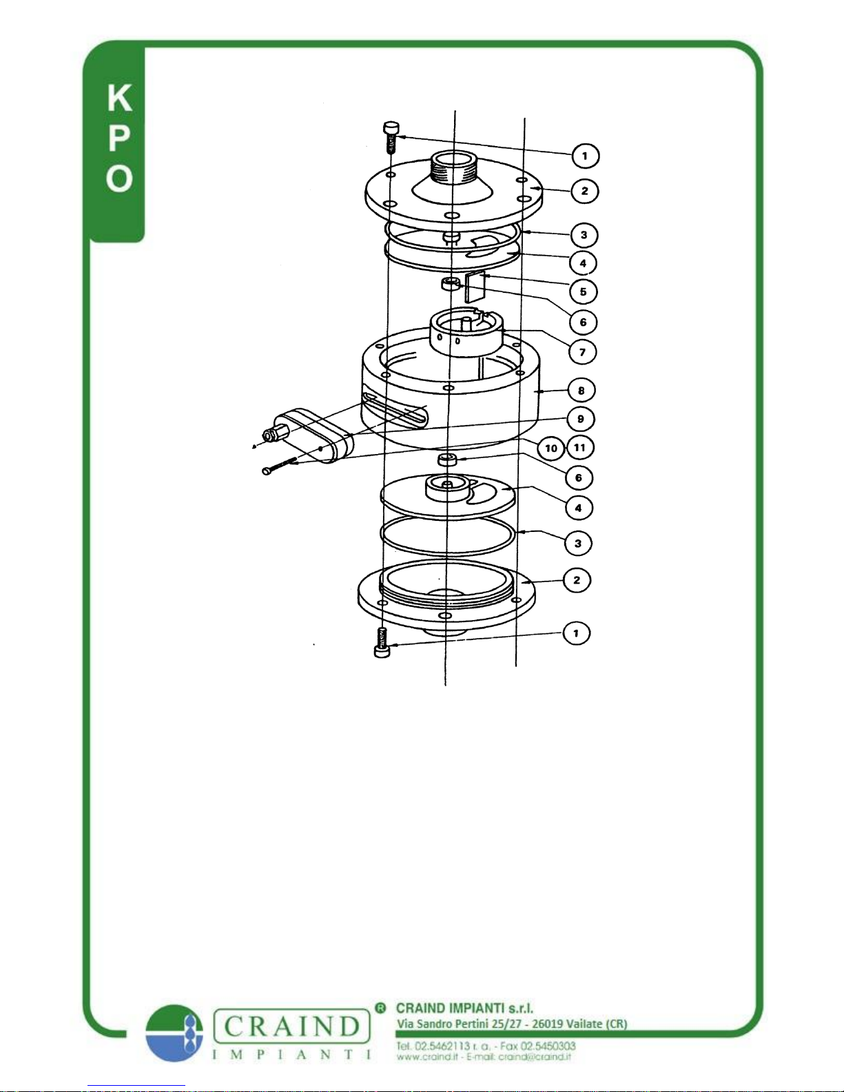
Bodyscrew 9)reed switch Screw
1)End Nate 10)Reed switch Washer
2)'O' Ring
3)Plate Assd.
4)Barrier
5)Roller
6) Piston
7)Body
8)Reed Switch Pag.6

Spare parts
It is recommende that the following parts be held in stock as
spares:
N. piston
N.1 Reed switch
N.2 roller (only for 2" and 3"meters)
N.1 barrier plate
N.2 'O"rings seal
ASSOCIATED EQUIPMENT
Filters
In order to guard against seizure of the meter working parts, due to
the ingress of oversized particles too large to be swept through the
meter, it is recommended that filter be fitted up-stream of the meter
to filterout particles in excess of 0,1 mm in diameter. For further
infomation do not exitate to contact our Technical Department in
CRAIND IMPIANTI
Valves
Remotely controlled valves, when fitted, should be of the fast
closingtype to minimized the effect of over-run at the end of a
batch delivery. Generally, pneumatically operated valves are
recomended. Our Technical Department in CRAIND IMPIANTI
will be pleased to offer a suitably spiced valve to suit your
requirements.
Pumps
Use pumps free from pulsation (centrifugal or volumetric types).
Positive displace rent pumps inherently produce pulsations which
can cause measurement errors.
Air Separation
If thereis danger of entrained air being present in the liquid then a
suitable de-aeration device must be installed upstream of the meter
otherwise air will be measured as liquid.
Pag.7

HYGIENICDESIGN
The body components (s.s. version) are manufactured from
AISI 316 stainless steel and are ready dismantled for
maintenance and cleaning. Due to the hygienic design and
self-flushing action, the mete, lends itself to in-line steam
sterilization. As a result the CRAIND IMPIANTI KPO meter
is used in a wide renge of applications in the brewing,
distilling, food ,drinks and pharmaceutical industries.
CLEANING IN SITE
When a system is to be cleaned in place, sterilized or purged
without removal of the meter from the line, it is advisable to
provi de the meter with a by-pass to prevent damage
occurring to the internal working parts unless the following
reccommenations can be adhered to:
Liquid detergent temperatures in excess of the maximum
stated in the meter speciation should not be used for
cleaning purposes or distortion and expansion of the piston
will result, causing the piston to "bind"within the chamber.
Check that cleaning fluid will not attack or corrode the
material of the meter.
Sterelization with steam is not admitted. If it is necessary
the pressure of the in-coming steam to the meter must be
carefully controlled so that the velocity of the piston
within the chamber is kept below 75% of its maximum
velocity when metering with liquids. The sane must be
done when purging the system with air.
After steam sterilization or air purging during re-charging
of the pipe with fluid, care must be taken to avoid impact
of high speed fluid re-entering the empty measuring
chamber.
Pag.8

ATTENTION:• It is very dangerous to empty the mete,
by using air, nitrogen or steam. If it !s necessary be very
careful during the operation. Moment emptying will
inevitably damage the piston
TECHNICAL CARATTERISTCHS AND MATERIALS
MODEL
LO
MODEL
PORTATA
FLOW RATE
IMPULS
I
PULSES
AISI316
PVC
POLIPRO
P.
PVDF
Min Max
I/b
cc x imp
T
max
°C
P
max
bar
T
max
°C
P
max
bar
T
max
°C
P
max
bar
T
max
°C
P
max
bar
KPO'/:"
30 400
8,5
80
10
KPO1"
200 2.200
50
80
10
35
3,5
45
3,5
60
3,5
KPO1'/"
400 6.000
220
80
10
35
3,5
45
3,5
_60
3,5
I~O 2"
500 9.000
500
80
10
35
3,5
45
3,5
60
3,5
KPO 3"
800 20.000
500(2
reed)
80
10
35
3,5
45
3,5
60
3,5
emitted pulses number is theoretical and it refers to water
PISTONS MATERIALS : PTFE - PVC -
ALLUMINIO - PIK MOD.
O.R MATERIALS:VITON - Pl I-E - EPDM –
NITRILE
SENSOR TYPE
following types of sensor are available
REED
HALL EFFECT
HALL EFFECT
Pag.9

CYCLE OF OPERATION
FIG.1
The piston is over the inlet port, the inflowing liquid has
entered the incide wall of the piston and is causing it to start
its semi-rotary movement, sliding down the division piece,
displacing the neutral liquid which becomes the out owing
liquid as it is expelled through the outlet port.
FIG.2
Shows the above operation taking place with the inflowing
liquid both inside and outside the piston
FIG.3
Shows the inflowing liquid on the inlet ride of the chamber
with the neutral liquid on the incide of the piston and with the
out owing liquid passing to the outlet port.
FIG.4
Shows the completion of the exhaust period and the
commencement of the inlet period.
FAULT FINDING
If the metering system is not functioning correctly:
First check the operation of the indicator or control instrument
correctly:
Disconnect the signal input connections to the instrument and
simulate the pulsations of the reed switch at the meter by
intermittently short circuiting the input signal terminals at the
rear of the instrument. If the appropriate pulses are not
received on the indicating or control equipment, then these
units must be checked as described in the appropriate
instruction manual. If pulses are received and indicated then
re-connect a signal input cable.
Check that the interconnection cable is satisfactory by:
Disconnecting the other end of the cable from the reed switch
connection. Short circuit the conductors and see whether or
not pulses are received on the control equipment at the other
end of signal cable. If pulses are not received then there is a
break somewhere in the interconnection cable and it should be
replaced. If pulses are received re-connect the cable.
Pag.10

Check the operation of the reed switch by:
Remove the reed switch assembly from the meter and
connect a battery ohm meter.
Pass a normal magnet across of the reed switch and if the
resistance changes from at least I mega ohm to less than I ohm
due to the movement of the magnet, the reed switch is
operative.
To check that the piston is rotating whilst liquid is flowing:
1)Hold an ordinary magnetic compass near the reed switch
recess in the meter body. If the needle oscillates wildly the
piston is moving.
2)A visual ( check can be made on the quantity of liquid
flowing through the system with the control device fully
open. If the flow rate is drastically below that normally
delivered the piston could be stationary and helping to
produce a prohibitive head loss across the meter.
3)Adjust the system flow rate to its maximum and check for
a slight vibration of the meter caused by a rotating piston. If
all the previouslymentioned checks prove satisfactory then
the meter must be removed front the line and dismantled and
inspected as detailed in maintenance sections.
Possible causes of imperfect operation are:
1)A fractured piston allowing the passing of unmetered
fluid.
2)Resistance to motion of the piston due to:
- Particles of foreign matter embedded in the working
surfaces of the meter.
- A "gummed up "meter due to ineffective
temperature control or. settling out during "shut or.
- A distorted piston due to operation at
temperatures in excess of the maximum allow .
- Worn barrier or rollers allowing the piston to "cock"
during operation are not in the right position.
- Bent piston pegs due to excessive pressure drop
across the meter.
Pag.11

This addict istructions and informations completate the
istruction’s manual and the standard’s service.
1- What operating
features have
Your equipment?
1.1 - Marking and
esplications.
All of Yours equipment have this label
Pag.12
ATEX: ADDICT
ISTRUCTIONS AND
IN FORMATION

II 2 GD c T4 X
2- THE DATAS THAT YOU MUST CONTROL DURING
THE OPERATION
DANGER EXPLOSION!
The observance of the instruction contained in this chapter can
be produce severe damages to the people,
or it can be cause the death! This instructions don’t prescind
from an appropriate utilization of the equipment
and from the istructions on the generic instruction’s manual.
Pag.13

Note 1: refer to the individual instructions for the other
accessory united to the meter.
Note 2: all meters must be assembled with this follow addict
precaution
Pag.14
ATEX: ADDICT
ISTRUCTIONS AND
IN FORMATION
Table of contents
Other Craind Impianti Measuring Instrument manuals

Popular Measuring Instrument manuals by other brands


Mgl
Mgl Blaze AHRS-2 operating manual

Campbell
Campbell 109B instruction manual

Pessl Instruments
Pessl Instruments METOS LoRAIN NBIoT user manual

CORNING
CORNING ONE OIU Quick installation sheet

Mirion Technologies
Mirion Technologies TelePole II user guide

Endress+Hauser
Endress+Hauser Prothermo NMT 538 operating manual

Hama
Hama 00137289 operating instructions

PCB Piezotronics
PCB Piezotronics IMI SENSORS 637A06 Installation and operating manual

ADVANTEST
ADVANTEST R3267 series Operation manual

ALCO
ALCO AL-82933 Installation and use instruction

Honeywell
Honeywell Enraf 977 instruction manual

PIETRO FIORENTINI
PIETRO FIORENTINI MODUS Series Technical manual