Crane Electronics TCI Multi User manual

1
Operators Manual
Tool Control Interface (TCI) Multi
Manual - Issue 2
Crane Electronics Ltd.
NOTICE
ALL RIGHTS RESERVED. Reproduction of any part of this manual in any form whatsoever,
without the prior permission in writing from Crane Electronics Ltd is forbidden.
Copyright © March 2021 by Crane Electronics Ltd

2
Contents 2
UKCA Marking, CE Marking & Compliance 3
Product Disposal & About this Manual 4
Packing List 5
Care & Storage / Warnings 5
Product Description 6
Dimensions 7
Specifications 8
TCI Web Pages 9
TCI Network Settings 11
TCI Wrench Status 12
TCI Log View 20
TCI RF Settings 21
TCI Jobs 22
TCI Rounds 23
TCI Global Settings 24
CONTENTS

3
Manufacturer: Crane Electronics Ltd
Address: 3 Watling Drive
Sketchley Meadows
Hinckley
Leicestershire
LE10 3EY
Tel: +44 (0)1455 25 14 88
Crane Electronics Limited declares that the TCI Multi has been assessed and complies with the UK regulatory
requirements.
Crane Electronics Limited declares that the TCI Multi has been assessed and complies with the requirements of
the relevant CE Directives.
This device complies with part 15 of the FCC rules. Operation is subject to the following two conditions: (1) this
device may not cause harmful interference, and (2) this device must accept any interference received,
including interference that may cause undesired operation.
NOTE: This equipment has been tested and found to comply with the limits for a Class B digital device,
pursuant to part 15 of the FCC Rules. These limits are designed to provide reasonable protection against
harmful interference in a residential environment. This equipment generates, uses, and can radiate radio
frequency energy and, if not installed and used in accordance with the instructions, may cause harmful
interference to radio communications. However, there is no guarantee that interference will not occur in
particular installations. If this equipment does cause harmful interference to radio or television reception
which can be determined by turning the equipment off and on, the user is encouraged to try to correct the
interference by one or more of the following measures:
• Reorient or relocate the receiving antenna.
• Increase the separation between the equipment and receiver.
• Connect the equipment into an outlet on a circuit different from that to which the receiver is connected.
• Consult the dealer or an experienced radio/TV technician for help.
ADDRESS
COMPLIANCE
UKCA MARKING
CE MARKING

4
Applicable in the EU and other European Countries with separate collection systems
The symbol shown here and, on the product, means that the product is classed as Electrical
or Electronics Equipment and should not be disposed with normal commercial waste at the
end of its working life.
The Waste of Electrical and Electronics Equipment (WEEE) Directive (2012/19/EU) has been put in place to
recycle products using best available recovery and recycling techniques to minimise the impact on the
environment, treat any hazardous substances and avoid the increasing landfill.
To enable this product to be disposed of properly i.e., cradle to grave, Crane Electronics is willing to accept the
return of your product (at your cost) for recycling or alternatively, for more detailed information about
recycling of this product please contact your local authority or the Distributor / Company where you have
purchased the product.
Battery disposal to take place in line with the AMENDED BATTERIES DIRECTIVE 2013/56/EU. Batteries must not
go to landfill. Check with local legislation.
Crane Electronics declares that this product does not contain any of the 191 Substances of Very High Concern
(SVHC’s) identified in the REACH Regulation in used articles make-up.
In Countries outside the EU:
If you wish to discard this product, please contact your local authorities and ask for the correct way of disposal.
Signed for & on behalf of Crane Electronics Ltd.
Name: B. M. Etter
Title: Safety & Environmental Advisor Signature of Issuer:
This manual covers the Tool Control Interface (TCI) working with a WrenchStar Multi (WSM) using RF.
Actual screen shots represented in this manual may differ slightly depending on version.
For information on the operation of a WrenchStar Multi please refer to its own manual.
PRODUCT DISPOSAL
ABOUT THIS MANUAL
WARNING
Changes or modifications to the Tool Control Interface (TCI) Multi not expressly approved by Crane Electronics Ltd
could void the user’s authority to operate the equipment.

5
The following items are supplied with the TCI Multi.
1 x Tool Control Interface
1 x User Manual
1 x Quick Start Guide
1 x 5V PSU
Please ensure all items are present and notify Crane Electronics Ltd immediately of any shortages.
Operating temperature range -20 to +50 degrees C
Storage temperature range -20 to +50 degrees C
Humidity 10-75% non-condensing
IP Rating IP40 (indoor use only)
The Tool Control Interface may be wiped clean with a soft cloth.
Maintain unit with care. Keep unit clean for better and safer performance.
Changes or modifications to the Tool Control Interface not expressly approved by Crane
Electronics Ltd could void the user’s authority to operate the equipment.
Always operate Tool Control Interface with approved PSU.
Always operate, inspect and maintain this unit in accordance with all regulations (local, state,
federal and country) that may apply.
Do not remove any labels.
Always use Personal Protective Equipment appropriate to the tool used and material worked.
Keep body stance balanced and firm. Do not overreach when operating with the tool. Anticipate
and be alert for sudden changes in motion, reaction torque, or forces during the operation.
Ensure work pieces are secure. Use clamps or vices to hold work pieces whenever possible.
Never use a damaged or malfunctioning tool or accessory with this unit.
Follow instructions for changing accessories.
Do not operate this product in explosive atmospheres, such as in the presence of flammable
liquids, gases or dust.
This unit contains no user serviceable parts. Only qualified service personnel should replace or fit
parts.
PACKING LIST
CARE AND STORAGE
WARNINGS

6
PRODUCT DESCRIPTION
Blue Button
for pairing
Mounting Hole (see
Page 7 for
dimensions)
RF Antenna
Status LED’s
Reset
Mini USB (programming
only)
RS232
RJ45 Ethernet
Power Socket
TDC
Data capture

7
Weight: 760g
Construction: Aluminium housing containing printed circuit boards.
Mounting Details
DIMENSIONS

8
Power: 5V +/-10% DC power supply 1000mA
Ethernet: Unique MAC Address
RJ45 Connection
10/100 MBit/s
Serial: 9-way D-type RS232 socket for serial connection to a PC in standalone mode.
USB: Mini USB Cable for programming firmware.
RF: 2400MHz antenna for RF Wrench communication that can be placed in different
orientations.
Low power 0dBm and uses worldwide ISM band (2400MHz).
Transducer:WrenchStar Multi. Maximum number 5.
Number of Jobs: Stores 256 different Jobs, any of which can be selected and downloaded to
WrenchStar Multi.
Offline mode: Downloads a Job to a WrenchStar Multi and uploads results when the WrenchStar
Multi is within range.
Polls WrenchStar Multi to see if the results are available.
Pairing: Can be easily Paired with WrenchStar Multi using a single push Button operation or
via web Page.
Construction: Aluminium enclosure
Dimensions: 217mm x 120mm x 56mm
Weight: 760g
Mounting: Flange for mounting to a surface with 4 bolts. (See pg. 6)
LEDs: Power Status
Host communication (informs whether the communications is good, absent
incorrect).
Wrench communication (informs whether the WrenchStar Multi is Paired, in range
or has a Job loaded).
TDC 9TCI Data Collector status – Connected or disconnected.
Operation: Accepts Open Protocol commands via Ethernet to select a Job and use with the
Wrench (tool).
Has Web Status Page that allows Ethernet properties, RF properties, logging of
messages, and Wrench Status to be monitored.
Wrench Status Web Page mirrors the LED Status on TCI and also shows last Torque
and Angle reading from Wrench plus its Torque Status (LO, OK and HI).
Standalone mode – Jobs can be selected and results posted to PC or Web Page.
Setup: Via Web Page.
Time / Date: Real Time Clock (read and write)
(TCI MULTI) SPECIFICATION

9
When you first login to the browser, you will see the Home Page. You can get back to the Home Page by
clicking on the “Home” Icon at any time.
There are 6 Web Pages that can be navigated to:
•TCI Network Settings
•Wrench Status
•Log View
•RF Settings
•Jobs Settings
•Global Settings
The Home Page will give the serial number of the TCI, and its current software versions for the main processor
and RF module.
There are 2 Comms Modes:
•Open Protocol (used by a variety of manufacturing systems)
•Standalone (when the factory network breaks down or if a simple manufacturing system)
The default IP and Port address is 192.168.0.101:80. The TCI returns to this IP address after a Factory Reset.
(Selecting Open Protocol variant 2 in global settings changes this default to 192.168.0.165)
Note: Before you plug the TCI into a corporate network, please involve the IT department to avoid IP conflicts.
The Web Pages are viewable on common web browsers such as MS Edge, Firefox, and Chrome. Internet
Explorer is not recommended.
To alter settings then you must “Login”. (See next picture)
TCI WEB PAGES

10
The default password is “Admin” and we advise that you change this by clicking on the “Change password”
Icon once logged in as Admin due to the password only remaining active for 5 minutes, after this time it will
need to be re-entered to continue Editing.
Once logged in, it is possible to perform a remote Factory Reset of the TCI as well as a change of language.
To manually perform a Factory Reset press and hold the Blue Button until all the LEDs are flashing (approx. 30
seconds). Release and re-press the Button within 10 seconds to confirm Factory Reset.
Once a Factory Reset has been done the following happens:
•Job’s list cleared – Jobs will need to be re-entered.
•Sets password to Admin
•Erases Pairing information – WrenchStar Multi will need to be re-Paired.
•In Open Protocol it will be necessary to receive a Comms Start MID
•The browser IP addresses will be 192.168.0.101 and Port 80 for HTML. (Selecting Open Protocol
variant 2 in global settings changes this default to 192.168.0.165)
•Port 4545 is the default Port for first Wrench (tool).
•Clears log files
•Restores some global settings to default
•Reset backups
11
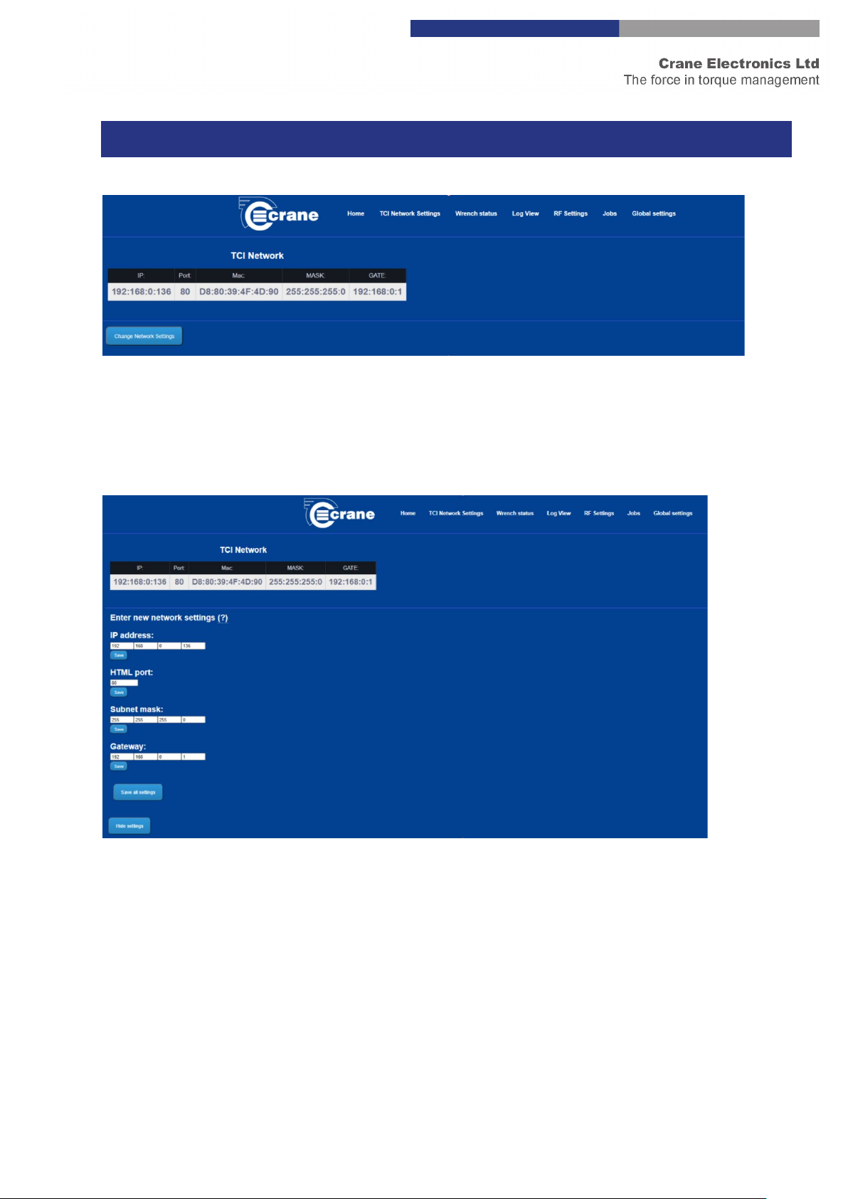
It shows the IP and Port address of the Web Pages.
The unique MAC address of the TCI is shown. This cannot be changed. This is useful if the IT system needs to
check a valid device is connected to a certain network node.
If the user is logged in then the Web Page will show a “Change Network Settings” Button.
If you click ‘Change Network Settings’ you can edit:
•IP Address
•HTML Port
•Subnet mask
•Gateway.
If the network settings are changed the TCI will re-boot itself which will cause the network connection to be
dropped with the browser. The browser will need to be refreshed and of course set to the new IP and Port
address.
TCI NETWORK SETTINGS
12
The Edit entry warns you if the number entered is incorrect.
IP address entry is from 0 to 255
Port entry is from 0 to 65353
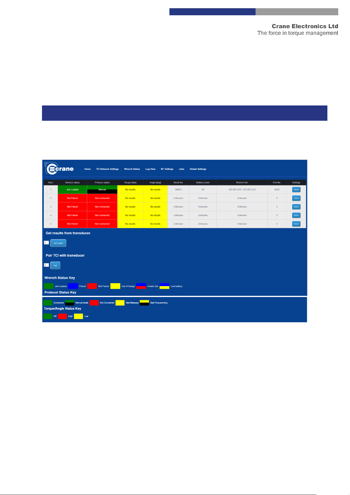
It shows the Status for up to 5 connected Wrenches.
Note: Info on Port 80 can be viewed at the same time as the measurement results are being transmitted to
Port 4545.
Each column shows different information:
•Wrench Status – gives colour coded information about the current state of the WrenchStar Multi.
The key for colours is shown at the bottom of the Page. These colours will match the Wrench Status
LED on the TCI.
oNote: The Out of Range – Yellow colour may also be seen if the WrenchStar Multi is turned
off. This colour is only seen once a WrenchStar Multi is Paired as it is then regularly polled to
check if it’s present and has any off-line results.
oThe Red/Blue colour on the TCI indicates that you will see Wrench Status LED flashing
between Red and Blue.
•The Protocol Status – gives colour coded information about the current state of the host connection.
The key for colours is shown at the bottom of the screenshot above. These colours will match the host
Status LED on the TCI.
o“Bad message” is an unrecognised host message
TCI WRENCH STATUS
13
oWill be “Connected” if a Start Comm MID was received and it continued to receive messages
or a Keep Alive MID message.
•The Torque and Angle result for the last reading will be displayed and colour coded the same as the
Light Ring on the WrenchStar Multi
oLess than LSL = Amber
oOkay = Green
oGreater than USL = Red
•The rest of the information is only updated when initially connected to the WrenchStar Multi:
oWrenchStar Multi serial number
oWrenchStar Multi battery level
oWrenchStar Multi software version
oPort number. The Port which the WrenchStar Multi is communicating to the host on (each
WrenchStar Multi has a unique Port ID for communication)
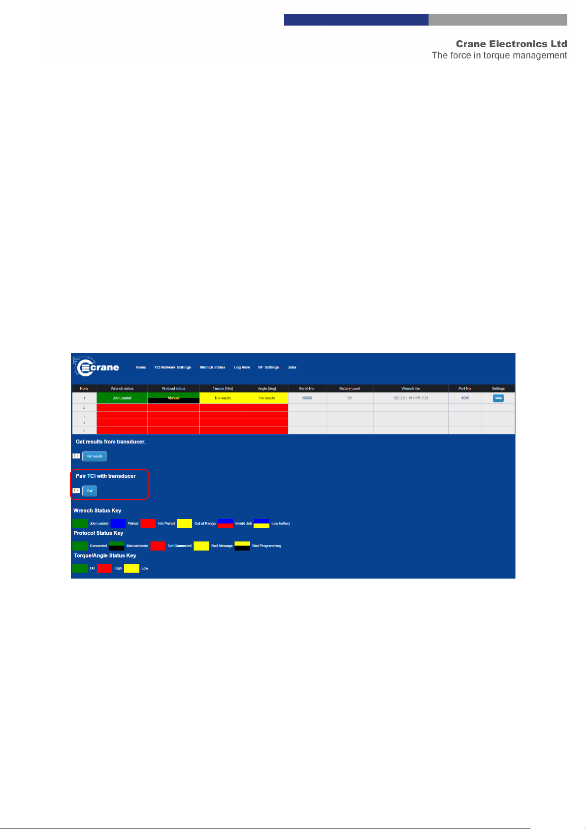
The following example of the Wrench Status Page shows: the Pair Transducer Button.
•First set the WrenchStar Multi into Pairing mode by holding its Blue Button until its Status LED turns
Purple. Then press TCI Pair Button. (Please see Wrench Span Pairing in the global settings section for
more options on which wrench is paired on which port)
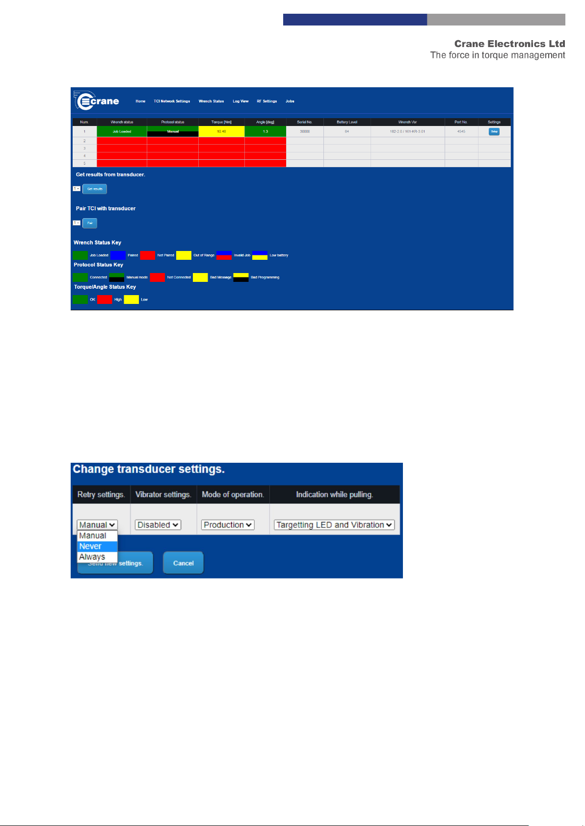
The following example of the Wrench Status Page shows:
•Its last result was a Torque of 10.48 Nm which was lower than LSL (Lower Spec Limit). When pressing
the setup button, the TCI will display all current settings stored on the wrench.
14
Change Transducer Settings – Retry Settings
This setting controls what happens when there is a NOK reading and when a retry should be triggered.
Never – Accepts any reading on the wrench and does not trigger retry.
Manual – Screen prompt when NOK giving the user the opportunity to save the reading and cancel the retry.
Always – NOK readings will not be excepted and a retry will always be triggered on a NOK.

15
Change Transducer Settings – Vibrator Settings
This setting enables/disables the vibrator.
Change Transducer Settings – Mode of Operation
There are two settings available, production and Audit. Audit gives the user more time to read the result on
the wrench after each reading and will zero the wrench before every new reading is taken. Production jumps
straight to the next job after a reading and only zeros the wrench when it is first turned on.
Change Transducer Settings – Indication while pulling
This setting changes the indication/feedback given by the wrench during the cycle.

16
Enabled
This setting enables the light ring during the cycle. The light ring will light amber for a low reading, green for an
OK reading and Red for a high reading.
This setting also enables the 3-vibration points spread out through the cycle. See the “Set vibrator activation
point” setting for more details.
Disabled
This disables all Light Ring and Vibration feedback on the wrench.
LED ON, Vibration OK
This setting enables the light ring during the cycle. The light ring will light amber for a low reading, green for an
OK reading and Red for a high reading. The vibrator will trigger when the wrench reaches OK status.
LED ON, Vibration HI
This setting enables the light ring during the cycle. The light ring will light amber for a low reading, green for an
OK reading and Red for a high reading. The vibrator will trigger when the wrench reaches Hi status.
LED OFF, Vibration OK
This setting disables the light ring during the cycle. The vibrator will trigger when the wrench reaches OK
status.
LED OFF, Vibration HI
This setting disables the light ring during the cycle. The vibrator will trigger when the wrench reaches Hi status.
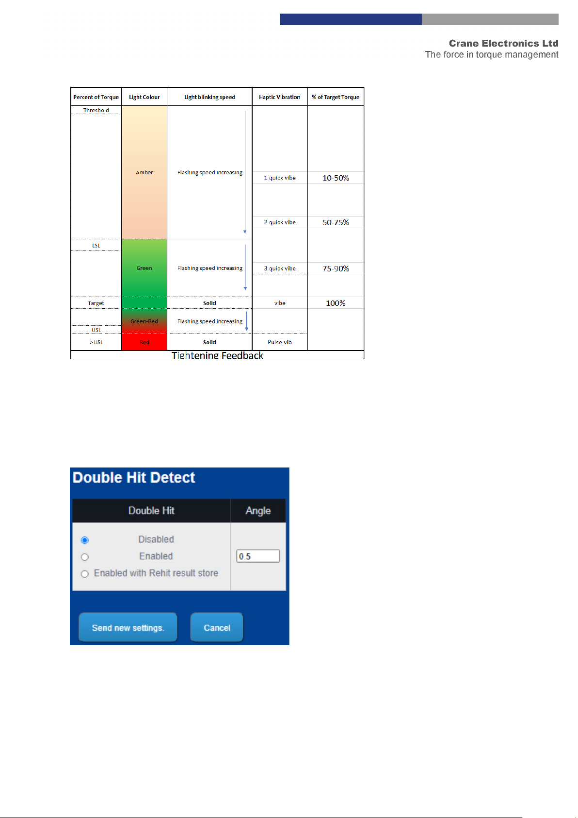
Targeting LED and Vibration
This is the most advanced feedback setting. For the most part in is like the “Enable” option with the following
differences:
•The wrench lights up solid Amber to signify there is a job loaded on the wrench.
•Once over threshold the light ring will flash slowly at first and then the speed of the flashing will
increase until the Torque passes LSL.
•At LSL the wrench will start flashing green slowly, increasing in speed until the wrench reaches target.
•At target the wrench will stay solid green +5%. There will also be a vibration.
•After target (+ 5%) the wrench will start flashing Green/Red slow, increasing in speed until USL is
reached.
•At USL the light ring will turn solid Red and there will be a hard long pulse vibration.
•There are 3 vibrations that happen between threshold and Target that can be adjust must like the
‘Enable’ setting however this is set using the “Change Feedback Start Point” setting.
See the following graphic that illustrates this further:
17
Double Hit Detect
This feature only works when pulling Torque in the clockwise direction. When the angle with the cycle is less
than the specified angle when this setting is enabled, there will be a NOK triggered for double hit. When
enabled with Rehit result store is selected the results for the NOK will be saved when it occurs.

18
Set Vibrator Activation Point
Controls the point at which the vibrator kicks in within a cycle when the indication while pulling setting is set to
‘Enabled’. There will be 3 vibrations that happen at different times in the cycle. This helps the user understand
where in the cycle they are at a given time. The smaller this figure the earlier in the cycle these vibration points
begin.
Change Trace Length
The trace length is setting the sample rate and the number of samples take within a given time period. The
maximum number of samples take in any cycle will be 1000. To capture the full cycle and obtain the best
resolution it is best to set the trace length as close to the time it takes to complete the cycle. See example
below.
Case 1 – User pulls for 1 second (cycle length), Trace length set to 4 seconds.
Number of samples captured = 250.
Sample Interval = 4ms
Case 2 – User pulls for 1 second (cycle length), Trace length set to 1 seconds. (Optimum)
Number of samples captured = 1000.
Sample Interval = 1ms
Case 3 – User pulls for 4 seconds (cycle length), Trace length set to 1 seconds.
Number of samples captured = 1000. (first second measured only)
Sample Interval = 1ms

19
Change Power Off Time
This setting sets the Auto Power of time on the wrench. This is highly recommended if the wrench isn’t docked
in the cradle between jobs and if multiple wrenches are being used with 1 TCI. The more wrenches on and
paired to the TCI, the greater the RF interference in that area.
Change Feedback Start Point
When using the “Targeting LED and Vibration” indication while pulling setting this changes at which point the
feedback on the wrench begins. This allows the user to delay indication to begin later in the cycle. For the
majority of cases the default setting of 10% will be optimal but in rare occasions (for example a really large
wrench on a really soft joint) this may be adjusted up to 50% to push all the feedback towards the end of the
cycle.
Change Open Protocol Port
This setting changes the TCP/IP port used to connect to the control the TCI via Open Protocol for this particular
wrench.

20
TCI Log View Page
The TCI can log message information to help diagnose problems.
The TCI has the option of viewing either host messages, or WrenchStar Multi messages, or both. The logging
options are setup via TCI Exchange.
The log information will appear in the “Log Box” which will display the latest messages or the last 1000
characters of messages if the TCI detects a problem.
The log text can be saved to a file (browse to requested folder) with the Save Button.
TCI RF Settings Page:
The RF Settings Page allows the properties of the TCI RF to be altered.
If the password has been entered the settings can be changed.
TCI LOG VIEW
TCI RF SETTINGS
Table of contents
Popular Recording Equipment manuals by other brands


Steinberg
Steinberg UR 824 Operation manual

Instruments of Things
Instruments of Things SOMI-1 user manual

Mitsubishi
Mitsubishi DX-TL5000E series Installer manual

Yamaha
Yamaha MOTIF-RACK owner's manual

Intellex
Intellex DV16000 Installation and operating instructions

TECHNOSAURUS
TECHNOSAURUS EFFEXON owner's manual


