Saab TransponderTech R5 RIC User manual

R5 RIC Quickstart
Page
1 (25)
Document Class
PT-CA
Document Id
Version
Date
7000 114-950
C1
2017-06-20
Saab TransponderTech AB
This document and attachments shall remain our property. They may not without our written consent, either in their original state or with any changes, be copied or
reproduced, disclosed to or delivered to anyone unauthorized nor used for other purposes than what has been confirmed by Saab TransponderTech in writing.
Saab TransponderTech AB, SWEDEN
PX-00-0050 A
Appendices
Project designation
R5 RIC
Document title
R5 RIC Quickstart

R5 RIC Quickstart
Page
2 (25)
Document Class
PT-CA
Document Id
Version
Date
7000 114-950
C1
2017-06-20
Saab TransponderTech AB
This document and attachments shall remain our property. They may not without our written consent, either in their original state or with any changes, be copied or
reproduced, disclosed to or delivered to anyone unauthorized nor used for other purposes than what has been confirmed by Saab TransponderTech in writing.
Saab TransponderTech AB, SWEDEN
PX-00-0050 A
CONTENTS
1References..............................................................................................................................4
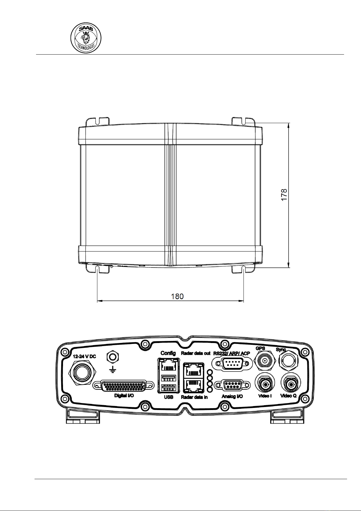
2Dimensions.............................................................................................................................5
3Connectors .............................................................................................................................6
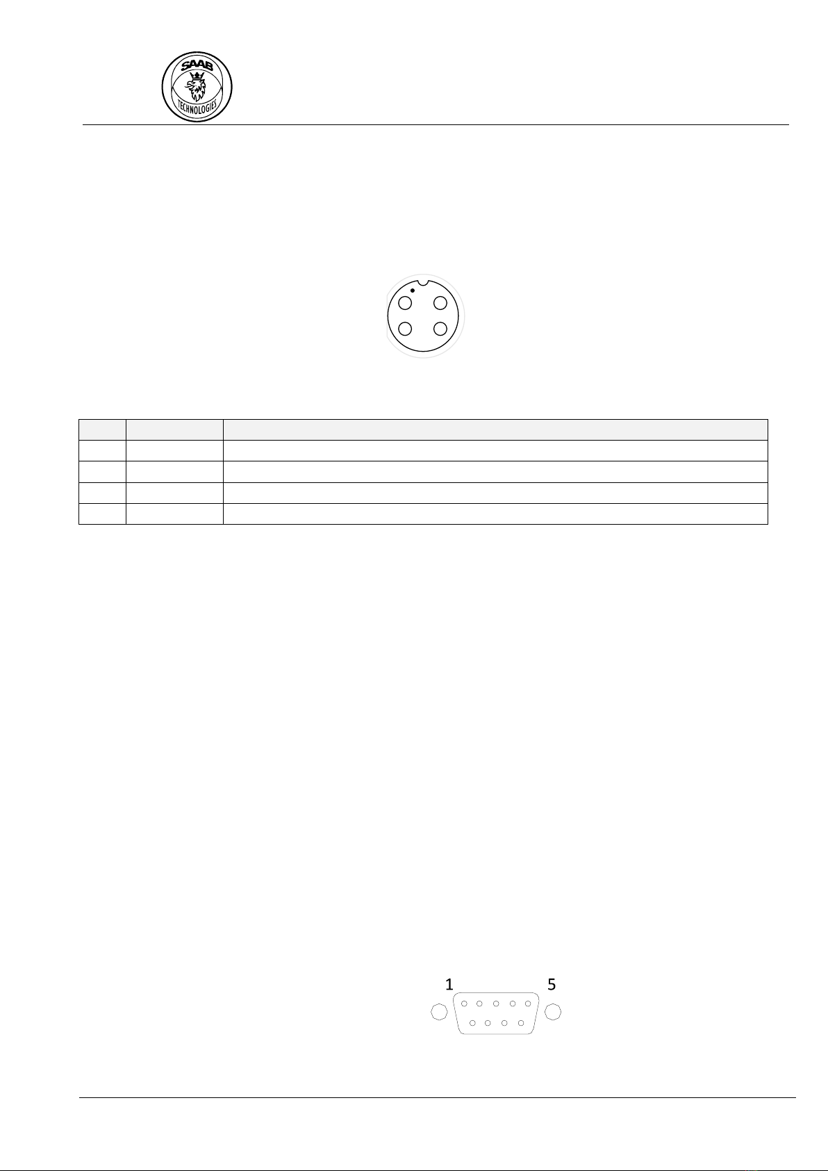
3.1 Power input.........................................................................................................................................6
3.2 Video I .................................................................................................................................................6
3.3 Video Q................................................................................................................................................6
3.4 Sync .....................................................................................................................................................6
3.5 GPS ......................................................................................................................................................6
3.6 RS232/ARP/ACP ..................................................................................................................................6
3.7 Radar data out ....................................................................................................................................7
3.8 Radar data in.......................................................................................................................................8
3.9 Config ..................................................................................................................................................8
3.10 Ground ................................................................................................................................................8
3.11 Digital I/O ............................................................................................................................................8
3.12 USB......................................................................................................................................................8
3.13 Analogue I/O .......................................................................................................................................8
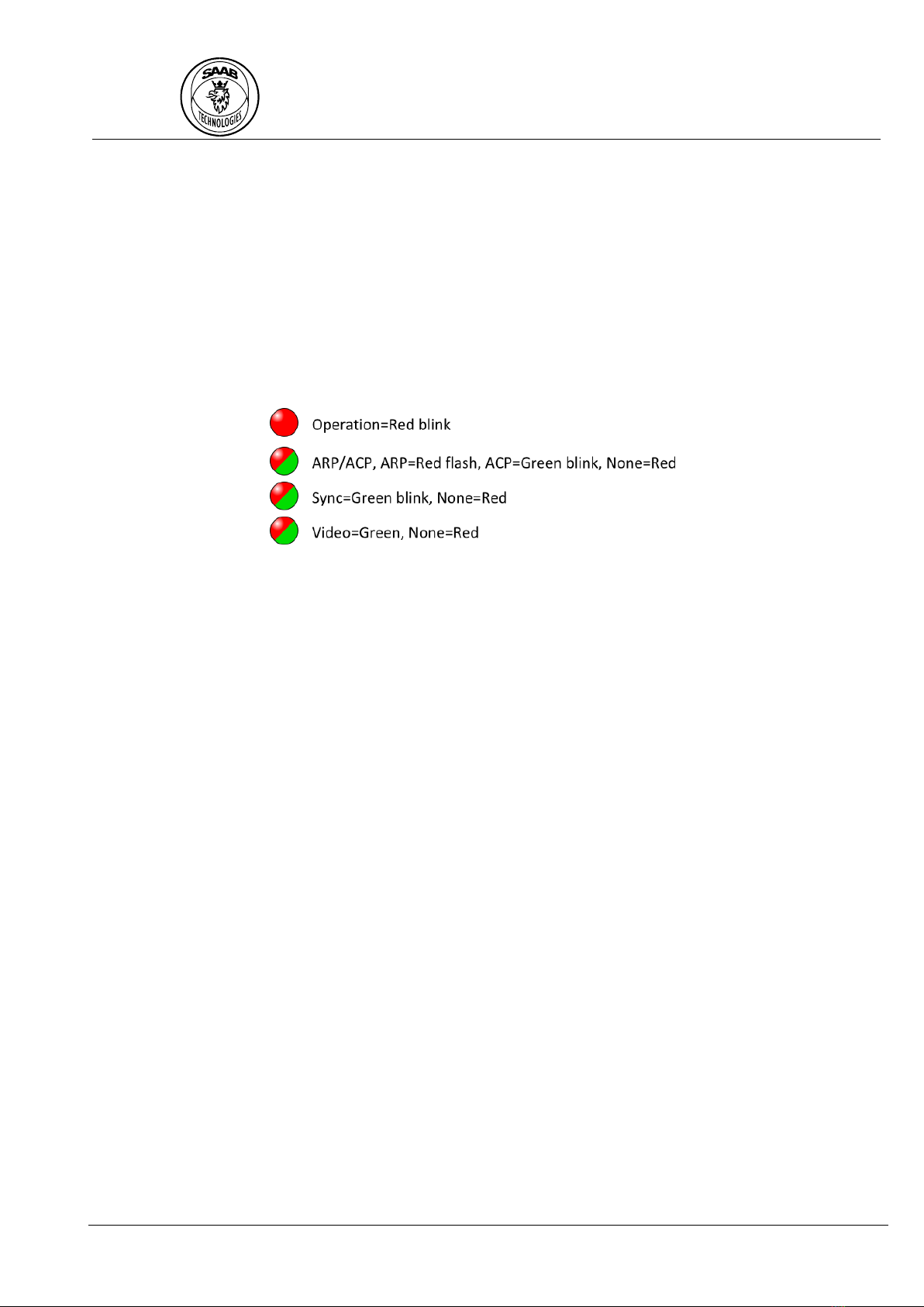
4Operation .............................................................................................................................10
4.1 Start-up .............................................................................................................................................10
5Configuration software ........................................................................................................11
5.1 Main window ....................................................................................................................................11
5.1.1 Opening a connect ...........................................................................................................................................12
5.1.2 Reloading all parameters .................................................................................................................................12
5.1.3 Changing a parameter......................................................................................................................................12
5.1.4 Storing the configuration .................................................................................................................................12
5.1.5 Reverting the configuration to stored configuration .......................................................................................12
5.1.6 Resetting the configuration to factory default.................................................................................................12
5.1.7 Rebooting .........................................................................................................................................................12
5.2 Configuration parameters.................................................................................................................12
5.2.1 Radar ................................................................................................................................................................13
5.2.2 Radar Video Input ............................................................................................................................................14
5.2.3 Radar Azimuth Input ........................................................................................................................................16
5.2.4 Radar Acquisition .............................................................................................................................................17
5.2.5 Raw Radar Video ..............................................................................................................................................18
5.2.6 Radar Video......................................................................................................................................................18
5.2.7 Configuration interface ....................................................................................................................................19
5.3 Web interface ...................................................................................................................................19
5.3.1 Maintenance Web interface ............................................................................................................................20
5.4 Serial interface ..................................................................................................................................21
5.4.1 Connect ............................................................................................................................................................21
5.4.2 Commands .......................................................................................................................................................22
6Installation............................................................................................................................24
6.1 Radars with analogue video output..................................................................................................24
6.2 Radars with composite analogue video output (e.g. Atlas)..............................................................24
6.3 Radars with digital radar video output .............................................................................................24
6.4 BridgeMaster radar...........................................................................................................................25

R5 RIC Quickstart
Page
3 (25)
Document Class
PT-CA
Document Id
Version
Date
7000 114-950
C1
2017-06-20
Saab TransponderTech AB
This document and attachments shall remain our property. They may not without our written consent, either in their original state or with any changes, be copied or
reproduced, disclosed to or delivered to anyone unauthorized nor used for other purposes than what has been confirmed by Saab TransponderTech in writing.
Saab TransponderTech AB, SWEDEN
PX-00-0050 A
Table of Figures
Figure 1, Positions for the mounting screws ............................................................................................5
Figure 2, Connectors .................................................................................................................................5
Figure 3, LED indicators description .......................................................................................................10
Figure 4, R5 RIC Configurator main window...........................................................................................11
Figure 5, Video adjustments ...................................................................................................................14
Figure 6, Atlas composite signal example. Multiple sync pulses visible.................................................15
Figure 7, Atlas composite signal with correct analogue gain and offset................................................16
Figure 8, Atlas composite signal correctly configured............................................................................16
Figure 9, Web-interface upper part ........................................................................................................19
Figure 10, Web interface lower part.......................................................................................................20
Figure 11, Maintenance window ............................................................................................................21
Figure 12, Tera Term - Connected to R5 RIC...........................................................................................22
Figure 13, Tera Term - get command......................................................................................................22
Figure 14, Tera Term - set command with valid and invalid values .......................................................23
Figure 15, BridgeMaster interconnection schematic (PT-16-0104 C3) ..................................................25

R5 RIC Quickstart
Page
4 (25)
Document Class
PT-CA
Document Id
Version
Date
7000 114-950
C1
2017-06-20
Saab TransponderTech AB
This document and attachments shall remain our property. They may not without our written consent, either in their original state or with any changes, be copied or
reproduced, disclosed to or delivered to anyone unauthorized nor used for other purposes than what has been confirmed by Saab TransponderTech in writing.
Saab TransponderTech AB, SWEDEN
PX-00-0050 A
1REFERENCES
7000 114-964, A1, R5 RIC Software Interface Specification. (n.d.). Saab AB.

R5 RIC Quickstart
Page
5 (25)
Document Class
PT-CA
Document Id
Version
Date
7000 114-950
C1
2017-06-20
Saab TransponderTech AB
This document and attachments shall remain our property. They may not without our written consent, either in their original state or with any changes, be copied or
reproduced, disclosed to or delivered to anyone unauthorized nor used for other purposes than what has been confirmed by Saab TransponderTech in writing.
Saab TransponderTech AB, SWEDEN
PX-00-0050 A
2DIMENSIONS
The dimensions of the R5 RIC are: length=192mm, width=227mm, height=77mm. The weight is 2.5kg.
Figure 1, Positions for the mounting screws
Figure 2, Connectors

R5 RIC Quickstart
Page
6 (25)
Document Class
PT-CA
Document Id
Version
Date
7000 114-950
C1
2017-06-20
Saab TransponderTech AB
This document and attachments shall remain our property. They may not without our written consent, either in their original state or with any changes, be copied or
reproduced, disclosed to or delivered to anyone unauthorized nor used for other purposes than what has been confirmed by Saab TransponderTech in writing.
Saab TransponderTech AB, SWEDEN
PX-00-0050 A
3CONNECTORS
3.1 Power input
The power input connector is a round 4-way connector (Switchcraft Conxall Mini-Con_X) with the
following pin-out.
Table 1, Pin-out description for power connector
Pin
Function
Description
1
12-24V DC
Positive voltage.
2
GND
Negative voltage.
3
Reserved
Leave floating.
4
Reserved
Leave floating.
3.2 Video I
The Video I connector should be connected to the analogue radar video interface. This is a BNC
connector that can be configured to be either differential or single ended. The termination can be
configured to 50Ω, 75Ω or no termination.
3.3 Video Q
The Video Q connector is used together with the Video I connector to interface radars with
quadrature video output. This is a BNC connector that can be configured to be either differential or
single ended. The termination can be configured to 50Ω, 75Ω or no termination.
3.4 Sync
The Sync connector should be connected to the sync pulse for the trigger output on the radar. This is
a BNC connector that can be configured to be either differential or single ended. The termination can
be configured to 75Ω, 120Ω, no termination or high voltage.
3.5 GPS
The GPS connector should not be connected. This TNC connector is for future use.
3.6 RS232/ARP/ACP
This connector is a male DSUB-9 connector.
The pin-out is described in Table 2.
3
41
2
Switchcraft Conxall Mini-Con- X
7381 - 4 PG-300

R5 RIC Quickstart
Page
7 (25)
Document Class
PT-CA
Document Id
Version
Date
7000 114-950
C1
2017-06-20
Saab TransponderTech AB
This document and attachments shall remain our property. They may not without our written consent, either in their original state or with any changes, be copied or
reproduced, disclosed to or delivered to anyone unauthorized nor used for other purposes than what has been confirmed by Saab TransponderTech in writing.
Saab TransponderTech AB, SWEDEN
PX-00-0050 A
Table 2, Pin-out description for RS232/ARP/ACP DSUB-9 connector
Pin
Function
Description
1
ACP+
Configurable Azimuth Counter Pulse input. Can be configured to be either
differential or single ended. The termination can be configured to 75Ω, 120Ω,
no termination or high voltage.
2
ACP-
3
ARP+
Configurable Azimuth Reset Pulse input. Can be configured to be either
differential or single ended. The termination can be configured to 75Ω, 120Ω,
no termination or high voltage.
4
ARP-
5
GND
Common ground for the serial pins.
6
RS232 RX
RS232 serial 1 receive and transmit pins. This can be used to configure the
unit through a RS232 serial connection.
7
RS232 TX
8
RS232 RX
RS232 serial 2 receive and transmit pins. This can be used for communication
between the unit and other equipment.
9
RS232 TX
To connect to the RS232 serial port 1, use connection parameters found in Table 3.
Table 3, RS232 serial interface connection parameters
Parameter
Value
Baud rate
115200
Data bits
8
Stop bits
1
Parity
None
Hardware control
None
3.7 Radar data out
The Radar data out connector is an Ethernet RJ45 (8P8C) connector. The radar data out should be
connected directly to a radar extractor computer due to the high data bandwidth, up to 1Gbit/s.
The default network configuration is:
Name
Value
Comment
MAC address
The MAC address is unique for each R5 RIC.
IPV4 Address
10.74.2.173
Only IPV4 is supported.
Radar data is sent as UDP broadcast from port 33000 to port 33000 by default. This interface does
not respond to any Ethernet requests (e.g. PING, etc.).

R5 RIC Quickstart
Page
8 (25)
Document Class
PT-CA
Document Id
Version
Date
7000 114-950
C1
2017-06-20
Saab TransponderTech AB
This document and attachments shall remain our property. They may not without our written consent, either in their original state or with any changes, be copied or
reproduced, disclosed to or delivered to anyone unauthorized nor used for other purposes than what has been confirmed by Saab TransponderTech in writing.
Saab TransponderTech AB, SWEDEN
PX-00-0050 A
3.8 Radar data in
The Radar data in connector is an Ethernet RJ45 (8P8C) connector that should be connected to a
radar with digital video out on Ethernet (for example Terma 2202).
3.9 Config
The Config connector is an Ethernet RJ45 (8P8C) connector that should be connected to an Ethernet
network for configuration and data exchange to/from an external system (for example CoastWatch).
The default network configuration is:
Name
Value
Comment
MAC address
The MAC address is unique for each R5 RIC.
IPV4 Address
10.74.2.172
Only IPV4 is supported.
IPV4 Gateway
10.74.2.1
IPV4 Netmask
255.255.255.0
3.10 Ground
M6 screw with two M6 nuts to connect cable lug. From this connector, a ground cable of minimum
2.5 mm² should be connected to the radar site ground. Grounding of the R5 RIC is essential to protect
the equipment from overvoltage.
3.11 Digital I/O
The digital I/O connector is a female 44-pin DSUB-HD.
3.12 USB
Two USB A connectors for future use.
The USB connectors can be used as a power source to other equipment. The maximum delivered
current is 1.0 A from each USB port.
3.13 Analogue I/O
The connector is a female 9-pin DSUB.
Pin-out description can be found in Table 4.
1
15
30 16
44 31
5 15
69

R5 RIC Quickstart
Page
9 (25)
Document Class
PT-CA
Document Id
Version
Date
7000 114-950
C1
2017-06-20
Saab TransponderTech AB
This document and attachments shall remain our property. They may not without our written consent, either in their original state or with any changes, be copied or
reproduced, disclosed to or delivered to anyone unauthorized nor used for other purposes than what has been confirmed by Saab TransponderTech in writing.
Saab TransponderTech AB, SWEDEN
PX-00-0050 A
Table 4, Analogue I/O pin-out description
Pin
Function
Description
1
ADC2
Analogue input channel 2. 0-5V
2
ADC4
Analogue input channel 4. 0-15V
3
DAC3
Analogue output channel 3. 0-15V
4
DAC4
Analogue output channel 4. 0-5V
5
GND
Ground.
6
ADC1
Analogue input channel 1. 0-5V
7
ADC3
Analogue input channel 3. 0-15V
8
DAC1
Analogue output channel 1. 0-15V
9
DAC2
Analogue output channel 2. 0-5V

R5 RIC Quickstart
Page
10 (25)
Document Class
PT-CA
Document Id
Version
Date
7000 114-950
C1
2017-06-20
Saab TransponderTech AB
This document and attachments shall remain our property. They may not without our written consent, either in their original state or with any changes, be copied or
reproduced, disclosed to or delivered to anyone unauthorized nor used for other purposes than what has been confirmed by Saab TransponderTech in writing.
Saab TransponderTech AB, SWEDEN
PX-00-0050 A
4OPERATION
4.1 Start-up
R5 RIC starts automatically when the power is supplied. After about 30 seconds the Operation LED
should start to flash.
The behaviour of the three lower LEDs can be found in Figure 3. Note that the behaviour of the three
lower LED indicators only is valid once the Operation LED has started to flash.
Figure 3, LED indicators description

R5 RIC Quickstart
Page
11 (25)
Document Class
PT-CA
Document Id
Version
Date
7000 114-950
C1
2017-06-20
Saab TransponderTech AB
This document and attachments shall remain our property. They may not without our written consent, either in their original state or with any changes, be copied or
reproduced, disclosed to or delivered to anyone unauthorized nor used for other purposes than what has been confirmed by Saab TransponderTech in writing.
Saab TransponderTech AB, SWEDEN
PX-00-0050 A
5CONFIGURATION SOFTWARE
The R5 RIC Configurator is a Saab supplied software for Windows OS. This software implements the
configuration protocol that enables a graphical interface for configuring a R5 RIC over Ethernet.
5.1 Main window
The following figure shows the main window when connected to a R5 RIC.
Figure 4, R5 RIC Configurator main window
The main window has the following areas of interest.
1. Menu bar
2. Operation log
3. Version of the connected R5 RIC
4. Configuration parameters
5. Configuration operations

R5 RIC Quickstart
Page
12 (25)
Document Class
PT-CA
Document Id
Version
Date
7000 114-950
C1
2017-06-20
Saab TransponderTech AB
This document and attachments shall remain our property. They may not without our written consent, either in their original state or with any changes, be copied or
reproduced, disclosed to or delivered to anyone unauthorized nor used for other purposes than what has been confirmed by Saab TransponderTech in writing.
Saab TransponderTech AB, SWEDEN
PX-00-0050 A
5.1.1 Opening a connect
To connect to a R5 RIC use the File menu item Open Connection. When this item has been selected a
connection dialog will pop up.
Enter the IP address for the R5 RIC configuration interface and press OK.
A progress bar will show in the lower right corner of the main window until connected. Any error that
occurs when connecting will show in the operation log.
5.1.2 Reloading all parameters
To reload all parameters use the Read button in the lower right corner of the main window. It is also
possible to do this through the menu item Operation →Read.
5.1.3 Changing a parameter
To change a parameter, edit the parameter in the main window and press the Write button in the
lower right corner of the main window. It is also possible to do this through the menu item
Operation →Write.
5.1.4 Storing the configuration
The R5 RIC requires the user to store the configuration to EEPROM if the configuration should be
loaded on boot.
To store the current configuration use the menu item Operation →Store.
5.1.5 Reverting the configuration to stored configuration
It is possible to revert the current configuration to the one stored on EEPROM. Use the menu item
Operation →Revert to revert the configuration. A pop-up will appear for confirmation.
Reverting the configuration will automatically overwrite the stored configuration.
5.1.6 Resetting the configuration to factory default
It is possible to reset the current configuration to the factory default. Use the menu item
Operation →Reset to reset the configuration.
5.1.7 Rebooting
It is possible to remotely reboot the R5 RIC. This is done through the menu item Operation →Reboot.
5.2 Configuration parameters
The following chapters describes the configuration parameters shown in the R5 RIC Configurator.

R5 RIC Quickstart
Page
13 (25)
Document Class
PT-CA
Document Id
Version
Date
7000 114-950
C1
2017-06-20
Saab TransponderTech AB
This document and attachments shall remain our property. They may not without our written consent, either in their original state or with any changes, be copied or
reproduced, disclosed to or delivered to anyone unauthorized nor used for other purposes than what has been confirmed by Saab TransponderTech in writing.
Saab TransponderTech AB, SWEDEN
PX-00-0050 A
5.2.1 Radar
In the radar group the user can configure the radar type and configuration parameters for the
selected radar type.
Name
Description
Radar
This selects the type of radar connected. This can be one of the following options. None,
ATM Air seeker, Atlas, Sperry Bridgemaster or Terma 2202. If the connected radar doesn’t
exist in the list, use None.
5.2.1.1 Sperry Bridgemaster
Name
Description
Power
Power up the transceiver. (Starts communication with the transceiver)
Transmit
Starts transmission. (Transmit/Standby)
Pulse length
Sets the pulse length.
AFC
Automatic Frequency Control On/Off.
LO tune
Coarse tuning of LO.
Tune indicator
LO tune indicator. (Read only)
Sector Blanking [1-3]
Begin
Sets the start angle 0-360 degrees for sector blanking (sector 1 of 3). The value “-1”
disables sector blanking.
Sector Blanking [1-3]
End
Sets the end angle 0-360 degrees for sector blanking (sector 1 of 3). The value “-1”
disables sector blanking.
5.2.1.2 Atlas
Name
Description
Positive sync polarity
Positive/negative sync polarity selection.
Video offset
Video offset tuning parameter.
5.2.1.3 Terma 2202
Name
Description
Transceiver address
Transceiver IPv4 address.

R5 RIC Quickstart
Page
14 (25)
Document Class
PT-CA
Document Id
Version
Date
7000 114-950
C1
2017-06-20
Saab TransponderTech AB
This document and attachments shall remain our property. They may not without our written consent, either in their original state or with any changes, be copied or
reproduced, disclosed to or delivered to anyone unauthorized nor used for other purposes than what has been confirmed by Saab TransponderTech in writing.
Saab TransponderTech AB, SWEDEN
PX-00-0050 A
5.2.2 Radar Video Input
These parameters configure the input ports for the analogue radar video signal.
Name
Description
Video signal
termination
The termination resistance for the analogue video input. This should be set according to
the video output on the radar. Valid selections: 50 Ω, 75 Ωor No termination.
Differential video
signal
Selects differential or single-ended signal input.
Video signal offset I
Video signal offset Q
Video signal offset adjustment. Used to adjust the video DC offset. See chapter 5.2.2.1.
Offset range is 0 to 1023.
The offset can be controlled for both channels (Iand Q) independently.
Video signal gain I
Video signal gain Q
Video signal gain adjustment. Used to adjust the video signal gain. See chapter 5.2.2.1.
Gain range is 0 to 1023.
The gain can be controlled for both channels (Iand Q) independently.
Sync signal
termination
The termination resistance for the video sync input. This should be set according to the
sync output on the radar. Valid selections: 50 Ω, 75 Ω, High voltage or No termination.
Differential sync
signal
Selects differential or single-ended signal input.
Sync edge
The edge of the sync signal on which the acquisition shall start. Rising or falling edge.
5.2.2.1 Analogue video capture adjustments
It is possible to adjust the capture of the analogue video signal to fit the signal levels of the radar
connected.
1. Configure the radar video input termination and differential parameters to match the radar
video signal from the radar.
2. Use the R5 RIC Analyser or other radar video A-scope to view the captured signal.
3. Adjust the data offset until the signal is in the middle of the scope.
4. Adjust the data gain until the signal touch the upper and lower scope edges.
Figure 5, Video adjustments
Offs e t Ga i n

R5 RIC Quickstart
Page
15 (25)
Document Class
PT-CA
Document Id
Version
Date
7000 114-950
C1
2017-06-20
Saab TransponderTech AB
This document and attachments shall remain our property. They may not without our written consent, either in their original state or with any changes, be copied or
reproduced, disclosed to or delivered to anyone unauthorized nor used for other purposes than what has been confirmed by Saab TransponderTech in writing.
Saab TransponderTech AB, SWEDEN
PX-00-0050 A
5.2.2.2 Atlas analogue video capture adjustments
For the Atlas radar, the analogue video capture adjustments must be done slightly differently due to
the composite signal.
It is important that the R5 RIC is able to detect and separate the azimuth information from the video
signal.
1. Configure the radar video input termination and differential parameters to match the radar
video signal from the radar.
2. Make sure to configure the R5 RIC to radar “Atlas”, that the Atlas “Video offset” parameter is
zero and then use the R5 RIC Analyser or other radar video A-scope to view the captured
signal.
3. Adjust the video input data offset, data gain, sampling frequency and number of samples until
the signal can be seen as in Figure 6. The video will move around before the composite sync
has been detected.
Figure 6, Atlas composite signal example. Multiple sync pulses visible.
4. Identify the sync pulse in the video. In Figure 6, the sync is seen pointing upwards. The easiest
way to identify the sync signal is to locate the azimuth bars. The azimuth information is
negative in regards to the sync pulse.
If the sync is positive, configure the R5 RIC with “Positive sync polarity” under the atlas
specific configuration parameters.
5. Adjust the video input gain and offset so that only a small portion of the sync and initial
azimuth pulse is visible. See Figure 7.
Note that once the sync pulse reaches the upper (or lower if negative) limit of the R5 RIC
Analyzer window, the system will lock-on the sync and the video will stabilize. The azimuth
information will also be extracted and presented in the azimuth field of R5 RIC Analyzer.

R5 RIC Quickstart
Page
16 (25)
Document Class
PT-CA
Document Id
Version
Date
7000 114-950
C1
2017-06-20
Saab TransponderTech AB
This document and attachments shall remain our property. They may not without our written consent, either in their original state or with any changes, be copied or
reproduced, disclosed to or delivered to anyone unauthorized nor used for other purposes than what has been confirmed by Saab TransponderTech in writing.
Saab TransponderTech AB, SWEDEN
PX-00-0050 A
Figure 7, Atlas composite signal with correct analogue gain and offset.
6. Set sampling frequency and number of samples so that the azimuth bars no longer are visible.
7. If the signal is negative as in Figure 7, set the “Data invert” configuration parameter.
8. Adjust the Atlas video offset until the video lies just above the bottom of the R5 RIC Analyzer
window. See figure Figure 8.
Figure 8, Atlas composite signal correctly configured.
5.2.3 Radar Azimuth Input
The radar azimuth parameters configure the azimuth source parameters.
Name
Description
Azimuth source
Selects the azimuth source. Can be either ARP/ACP or Syncro. Note that the Syncro option,
7000 114-901, must be installed in order to use Syncro as azimuth source.
ARP signal
termination
The termination resistance for the input. This should be set according to the ARP output on
the radar. Valid selections: 75 Ω, 120 Ω, High voltage or No termination.
Only applicable for ARP/ACP source.
Differential ARP
signal
Selects differential or single-ended signal handling.
Only applicable for ARP/ACP source.

R5 RIC Quickstart
Page
17 (25)
Document Class
PT-CA
Document Id
Version
Date
7000 114-950
C1
2017-06-20
Saab TransponderTech AB
This document and attachments shall remain our property. They may not without our written consent, either in their original state or with any changes, be copied or
reproduced, disclosed to or delivered to anyone unauthorized nor used for other purposes than what has been confirmed by Saab TransponderTech in writing.
Saab TransponderTech AB, SWEDEN
PX-00-0050 A
ACP signal
termination
The termination resistance for the input. This should be set according to the ACP output on
the radar. Valid selections: 75 Ω, 120 Ω, High voltage or No termination.
Only applicable for ARP/ACP source.
Differential ACP
signal
Selects differential or single-ended signal handling.
Only applicable for ARP/ACP source.
Max Azimuth
The number of azimuth steps per revolution. Used to detect if the incoming pulses
correspond to the correct number of pulses per antenna revolution.
5.2.4 Radar Acquisition
These configurations parameters are used to control the acquisition and signal processing of the
analogue radar video.
Name
Description
Channel
Channel selection of either channel I or channel Q.
Frequency
The sample frequency of the digitized radar video.
Can be configured from 100 kHz to 100 MHz.
Samples
Number of samples to capture. Can be configured as 64 to 8192 samples.
Downsampling
operation
Operation used to select samples when down sampling.
This feature performs a down sampling in range. I.e. reduces the range resolution.
Last - The last sample in each sample set is used
Max - The maximum sample in each sample set is used
Data type
The data type of the radar video samples sent from the R5 RIC. Must be 8-bit or 16-bit
when using STT packages.
Enable pulse
integration
Enables pulse integration.
Pulse integration integrates echoes over a number of strobes to increase detectability of
weak signals.
Pulse integration
level
Number of strobes to integrate using pulse integration.
Can be set from 1 to 8.
Enable FTC
Enables the FTC (edge detect) filter function.
The FTC filter in R5 RIC is based on a moving average function that is used to detect rising
edges of slow moving targets.
FTC level
Number of samples used for the FTC filter function.
Can be set to 4, 8, 16, 32, 64, 128, 256 or 512 samples.
FTC gain
A gain that can be applied after the FTC in order to increase amplitude of the filtered data.
Can be set to the factors x1, x2, x4, x8, x16, x32, x64 or x128.
Data invert
Inverts the samples. i.e. 122 become 65413 when using 16-bit samples.
Used for radars with inverted radar video signal.

R5 RIC Quickstart
Page
18 (25)
Document Class
PT-CA
Document Id
Version
Date
7000 114-950
C1
2017-06-20
Saab TransponderTech AB
This document and attachments shall remain our property. They may not without our written consent, either in their original state or with any changes, be copied or
reproduced, disclosed to or delivered to anyone unauthorized nor used for other purposes than what has been confirmed by Saab TransponderTech in writing.
Saab TransponderTech AB, SWEDEN
PX-00-0050 A
5.2.5 Raw Radar Video
These parameters configure the network parameters for the Raw radar video packages sent on the
Radar data out port.
Name
Description
Sector Downsample
Enables down sampling to sectors.
This feature is a down sampling in azimuth. I.e. reduces azimuth resolution.
Sector Count
The number of sectors that shall be sent from the R5 RIC. Must be greater than or equal to
8, and less than or equal to the number of azimuth steps for the antenna.
Only applicable when sector down sampling is enabled.
Sector downsampling
operation
Operation used to select samples when down sampling.
Last, The last sample in each sample set is used
Max, The maximum sample in each sample set is used
MAC Address
The MAC address for the radar video Ethernet interface.
IPv4 Address
The IPV4 address for the radar video Ethernet interface.
Source port
The UDP source port for radar video packages.
Destination port
The UDP destination port for radar video packages.
Package type
Selects the radar video package type.
The options are STT, STTv2RAW and Asterix.
Configure Package
Only applicable for STTv2RAW and Asterix packages.
For information regarding the digital radar video protocols STT, STTv2RAW and Asterix, see (7000
114-964, A1, R5 RIC Software Interface Specification).
5.2.6 Radar Video
These parameters configure the network parameters for the radar video packages sent on the Config
port.
Name
Description
Enable
Enables the video output.
Address
Destination address for the radar video Ethernet interface.
Port
Destination port for radar video packages.
Compression
None or RLE.
Threshold Min
Min threshold level for the video signal. Values below the threshold will be set to 0.
Threshold Max
Max threshold level for the video signal. Values above the threshold will be set to max
value.

R5 RIC Quickstart
Page
19 (25)
Document Class
PT-CA
Document Id
Version
Date
7000 114-950
C1
2017-06-20
Saab TransponderTech AB
This document and attachments shall remain our property. They may not without our written consent, either in their original state or with any changes, be copied or
reproduced, disclosed to or delivered to anyone unauthorized nor used for other purposes than what has been confirmed by Saab TransponderTech in writing.
Saab TransponderTech AB, SWEDEN
PX-00-0050 A
5.2.7 Configuration interface
This configures the network parameters for the configuration interface.
Name
Description
Enable web
configuration
Enable or disable configuration access in the web interface.
MAC Address
The MAC address of the configuration interface Ethernet port. Not writable.
IPV4 Address
The IPV4 address of the configuration interface.
IPV4 Net mask
The IPV4 net mask of the configuration interface.
IPV4 Gateway
The IPV4 gateway of the configuration interface.
IPV4 Name server
The address to up to 3 name servers.
IPV4 NTP server
The address to up to 3 NTP servers that the built in NTP client will connect to. The time is
used to time-stamp the radar video.
5.3 Web interface
Inside the R5RIC there is a web-server available on the Config Ethernet port. Using a web browser,
type in the IP-address of the R5RIC and the status/configuration page will appear (see Figure 9).
Figure 9, Web-interface upper part
1

R5 RIC Quickstart
Page
20 (25)
Document Class
PT-CA
Document Id
Version
Date
7000 114-950
C1
2017-06-20
Saab TransponderTech AB
This document and attachments shall remain our property. They may not without our written consent, either in their original state or with any changes, be copied or
reproduced, disclosed to or delivered to anyone unauthorized nor used for other purposes than what has been confirmed by Saab TransponderTech in writing.
Saab TransponderTech AB, SWEDEN
PX-00-0050 A
Figure 10, Web interface lower part
The main window has the following areas of interest:
1. There are 6 indicator symbols. The first three status information indicators are for ACP, ARP
and Sync. These indicators are green when the corresponding signals are present, and red if
they are not. The RPM figure is calculated from the time between two ARP pulses. The sync
frequency is calculated from the time between 2 sync pulses. The last status symbol is green
when the azimuth pulses (ACP) correspond with the configured Max Azimuth value.
2. Parameters and system status
3. In the access field it is possible to get and set values for all configurable parameters. This is
done by writing the parameter name (auto-complete is available), and then either use the get
or set button.
To store the value use R5RIC configurator (see section 5).
5.3.1 Maintenance Web interface
With a web browser type the IP-address of the R5RIC followed by /maintenance and the maintenance
page will appear (see Figure 11). On this page it is possible to both upload and download the
complete configuration to/from the R5RIC and to perform software upgrade.
2
3
Table of contents
Popular Recording Equipment manuals by other brands

National Instruments
National Instruments NI 951x user manual

Black Lion Audio
Black Lion Audio PBR TRS3 Patchbay owner's manual

Nady Audio
Nady Audio MSE-100A owner's manual

Sonifex
Sonifex RM-MC1L Handbook

Pioneer
Pioneer GR-555 operating instructions

Novell
Novell LINUX ENTERPRISE 10 SP1 - LINUX AUDIT quick guide