Crane Merchandising Systems 327 User manual


This machine has been engineered to our own rigid safety and performance standards. It
has been designed to comply with sanitation and health guidelines recommended by the
Automatic Merchandising Health-Industry Council (AMHIC) and it conforms with all other
NAMA safety recommendations.
This machine has been manufactured in accordance with the safety standards of both
Underwriter’s Laboratories and the Canadian Standards Association. To maintain this
degree of safety and to continue to achieve the level of performance built into this machine,
it is important that installation and maintenance be performed so as to not alter the original
construction or wiring and that replacement parts are as specified in the Parts Manual. Your
investment in this equipment will be protected by using the Operator’s Guide and this Parts
Manual in your operation, service and maintenance work. By following prescribed proce-
dures, machine performance and safety will be preserved.

Cold Drink Center Parts Manual List of Figures
August, 2003 i 3280033
List of Figures
Section A: Exterior of Door................................................................................................ 1
FIGURE 1: 328 Merchandiser ............................................................................................1
FIGURE 2: Trim - Millennia Style - Part 1 of 3 ...................................................................2
FIGURE 3: Trim - Millennia Style - Part 2 of 3 ...................................................................4
FIGURE 4: Trim - Millennia Style - Part 3 of 3 ...................................................................6
FIGURE 5: Trim - Standard Style ......................................................................................8
FIGURE 6: Door Assembly - Exterior ..............................................................................12
FIGURE 7: Display Assembly - Part 1 of 2 ......................................................................14
FIGURE 8: Display Assembly - Part 2 of 2 ......................................................................16
Section B: Interior of Door............................................................................................... 18
FIGURE 9: Door Assembly - Interior ................................................................................18
FIGURE 10: Lock Bar Assembly - Standard Style .............................................................20
FIGURE 11: Lock Bar Assembly - Millennia Style .............................................................22
FIGURE 12: Door Lock and Handle Assembly - Standard Style .......................................24
FIGURE 13: Door Lock and Handle Assembly - Millennia Style ........................................26
FIGURE 14: Fluorescent Lamp Assembly & Ballast ..........................................................28
FIGURE 15: Service Light Assembly .................................................................................30
FIGURE 16: Service Light & Bracket Assembly (UK/France/Germany) ............................32
Section C: Miscellaneous Cabinet .................................................................................. 34
FIGURE 17: Common Cabinet - Rear ...............................................................................34
FIGURE 18: Base Plate Assemblies ..................................................................................36
FIGURE 19: Leg, Leveler, and Leg and Hinge Assemblies ...............................................38
FIGURE 20: Door Hinge Assemblies .................................................................................40
FIGURE 21: Interlock Switch and Bracket .........................................................................42
FIGURE 22: Capacitor And Bracket Assembly ..................................................................44
Section D: Cup Station..................................................................................................... 46
FIGURE 23: Cup Station Assembly ...................................................................................46
FIGURE 24: Miscellaneous Cup Station Components ......................................................48
FIGURE 25: Delivery Door Assembly ................................................................................50
FIGURE 26: Center Plate Assemblies ...............................................................................52
FIGURE 27: Mechanism And Canister Assembly - Short ..................................................54
FIGURE 28: Turret and Canister Assembly - Short ...........................................................56
FIGURE 29: Mechanism and Canister Assembly - Large ..................................................58
FIGURE 30: Turret And Canister Assembly - Large ..........................................................60
FIGURE 31: Mechanism Assembly ...................................................................................62
FIGURE 32: Cup Mechanism Mounting Bracket Assembly ...............................................64
FIGURE 33: Cup Ring Assembly .......................................................................................66

List of Figures Cold Drink Center Parts Manual
3280033 ii August, 2003
List of Figures
Section E: Syrup Pump and Carbonator........................................................................ 68
FIGURE 34: Syrup Pump Assembly ................................................................................. 68
FIGURE 35: Syrup Pump CO2 Regulator Assembly ........................................................ 70
FIGURE 36: Gas Assist Syrup Pump and Bracket Assembly ........................................... 72
FIGURE 37: Bag-In-Box Connectors ................................................................................ 74
FIGURE 38: Syrup Tank Containers ................................................................................. 76
FIGURE 39: Diaphragm Syrup Pump and Bracket Assembly ........................................... 78
FIGURE 40: Diaphragm Syrup Pump ............................................................................... 80
FIGURE 41: Carbonator Final Assembly .......................................................................... 86
FIGURE 42: Component Covers ....................................................................................... 88
Section F: Water Bath Assembly.................................................................................... 90
FIGURE 43: Water Bath Assembly - Part 1 of 2 ............................................................... 90
FIGURE 44: Water Bath Assembly - Part 2 of 2 ............................................................... 92
FIGURE 45: Agitator Assembly - Water Bath .................................................................... 94
FIGURE 46: Water Valve Assembly - Non-Carbonated .................................................... 96
FIGURE 47: Hydrolife Water Filter .................................................................................... 98
FIGURE 48: Everpure Water Filter .................................................................................. 100
FIGURE 49: Overflow Switch Assembly ......................................................................... 102
Section G: Icemaker Assembly..................................................................................... 104
FIGURE 50: Icemaker Assembly .................................................................................... 104
FIGURE 51: Icemaker Components ................................................................................ 106
FIGURE 52: Hopper and Agitator Assemblies ................................................................ 108
FIGURE 53: Icelevel Components .................................................................................. 110
FIGURE 54: Icemaker - Miscellaneous Parts .................................................................. 112
FIGURE 55: Icemaker Motor ........................................................................................... 114
FIGURE 56: Water Feeder Assembly - USA/Germany ................................................... 116
FIGURE 57: Water Feeder Assembly - UK/France ......................................................... 118
FIGURE 58: Icemaker Condenser and Compressor ....................................................... 120
FIGURE 59: Pump and Valve Assembly - Coolsan ........................................................ 122
Section H: Monetary and Power ................................................................................... 124
FIGURE 60: Monetary Panel Assembly - Part 1 of 2 ...................................................... 124
FIGURE 61: Monetary Panel Assembly - Part 2 of 2 ...................................................... 126
FIGURE 62: Face Plate Assembly .................................................................................. 128
FIGURE 62A:Monetary Inserts - Upper Position.............................................................. 130
FIGURE 62B:Monetary Inserts - Lower Position.............................................................. 131
FIGURE 63: Coin Receptacle Assemblies ...................................................................... 132
FIGURE 64: Card Reader and Bill Validator Combinations ............................................ 134
FIGURE 65: Power Panel and PCB Assembly ............................................................... 138
FIGURE 66: Power Panel Assembly -115 V (U.S.) ......................................................... 140
FIGURE 67: Power Panel Assembly - UK ....................................................................... 142
FIGURE 68: Power Panel Assembly - 230 V - Fr/Gr (France/Germany) ........................ 144
FIGURE 69: Cabling Block Diagram (115 V) .................................................................. 146
FIGURE 70: Cabling Block Diagram (230 V) .................................................................. 148

Cold Drink Center Parts Manual List of Tables
August, 2003 iii 3280033
List of Tables
Section A: Exterior of Door.................................................................................................1
TABLE 1: 328 Merchandiser .......................................................................................................1
TABLE 2: Trim - Millennia Style - Part 1 of 3 ..............................................................................3
TABLE 3: Trim - Millennia Style - Part 2 of 3 ..............................................................................5
TABLE 4: Trim - Millennia Style - Part 3 of 3 ..............................................................................7
TABLE 5: Trim - Standard Style .................................................................................................9
TABLE 5A: Top Trim Panels - Standard Style ............................................................................10
TABLE 5B: Right Hand Trim Panels - Standard Style ................................................................10
TABLE 5C: Right Center Trim Panels - Standard Style ..............................................................10
TABLE 5D: Bottom Trim Panels - Standard Style .......................................................................11
TABLE 5E: Left Hand Trim Panels - Standard Style ...................................................................11
TABLE 5F: Left Center Trim Panels - Standard Style .................................................................11
TABLE 6: Door Assembly - Exterior .........................................................................................13
TABLE 7: Display Assembly - Part 1 of 2 .................................................................................15
TABLE 8: Display Assembly - Part 2 of 2 .................................................................................17
Section B: Interior of Door................................................................................................18
TABLE 9: Door Assembly - Interior ...........................................................................................19
TABLE 10: Lock Bar Assembly - Standard Style ........................................................................21
TABLE 11: Lock Bar Assembly - Millennia Style ........................................................................23
TABLE 12: Door Lock and Handle Assembly - Standard Style ..................................................25
TABLE 13: Door Lock and Handle Assembly - Millennia Style ...................................................27
TABLE 14: Fluorescent Lamp Assembly & Ballast .....................................................................29
TABLE 14A: Backlight Assembly (Not Shown) .............................................................................29
TABLE 15: Service Light Assembly ............................................................................................31
TABLE 16: Service Light & Bracket Assembly (UK/France/Germany) .......................................33
Section C: Miscellaneous Cabinet ...................................................................................34
TABLE 17: Common Cabinet - Rear ..........................................................................................35
TABLE 18: Base Plate Assemblies .............................................................................................37
TABLE 19: Leg, Leveler, and Leg and Hinge Assemblies ..........................................................39
TABLE 20: Door Hinge Assemblies ............................................................................................41
TABLE 21: Interlock Switch and Bracket ....................................................................................43
TABLE 22: Capacitor And Bracket Assembly .............................................................................45
Section D: Cup Station......................................................................................................46
TABLE 23: Cup Station Assembly ..............................................................................................47
TABLE 24: Miscellaneous Cup Station Components .................................................................49
TABLE 25: Delivery Door Assembly ...........................................................................................51
TABLE 26A: Center Plate Assembly - Common ...........................................................................53
TABLE 26B: Center Plate Assembly - Millennia ...........................................................................53
TABLE 27: Mechanism And Canister Assembly - Short .............................................................55
TABLE 28: Turret and Canister Assembly - Short ......................................................................57
TABLE 29: Mechanism and Canister Assembly - Large .............................................................59
TABLE 30: Turret And Canister Assembly - Large .....................................................................61
TABLE 31: Mechanism Assembly ..............................................................................................63
TABLE 32: Cup Mechanism Mounting Bracket Assembly ..........................................................65
TABLE 33: Cup Ring Assembly ..................................................................................................67

List of Tables Cold Drink Center Parts Manual
3280033 iv August, 2003
List of Tables
Section E: Syrup Pump and Carbonator......................................................................... 68
TABLE 34: Syrup Pump Assembly .............................................................................................69
TABLE 35: Syrup Pump CO2 Regulator Assembly ....................................................................71
TABLE 36: Gas Assist Syrup Pump and Bracket Assembly ......................................................73
TABLE 37: Bag-In-Box Connectors ............................................................................................ 75
TABLE 38: Syrup Tank Containers ............................................................................................ 77
TABLE 39: Diaphragm Syrup Pump and Bracket Assembly ......................................................79
TABLE 40: Diaphragm Syrup Pump ........................................................................................... 81
TABLE 40A: Tubing Usage - Model 328 .......................................................................................84
TABLE 40B: Tubing Usage - Model 327 .......................................................................................84
TABLE 40C: Tubing Usage - All Models and Countries ................................................................ 85
TABLE 41: Carbonator Final Assembly ...................................................................................... 87
TABLE 42: Component Covers ..................................................................................................89
Section F: Water Bath Assembly..................................................................................... 90
TABLE 43: Water Bath Assembly - Part 1 of 2 ...........................................................................91
TABLE 44: Water Bath Assembly - Part 2 of 2 ...........................................................................93
TABLE 45: Agitator Assembly - Water Bath ............................................................................... 95
TABLE 45A: Water Bath Refrigeration Components .................................................................... 95
TABLE 46: Water Valve Assembly - Non-Carbonated ...............................................................97
TABLE 47: Hydrolife Water Filter ............................................................................................... 99
TABLE 48: Everpure Water Filter ............................................................................................. 101
TABLE 49: Overflow Switch Assembly .....................................................................................103
Section G: Icemaker Assembly...................................................................................... 104
TABLE 50: Icemaker Assembly ................................................................................................105
TABLE 51: Icemaker Components ........................................................................................... 107
TABLE 52: Hopper and Agitator Assemblies ............................................................................ 109
TABLE 53: Icelevel Components .............................................................................................. 111
TABLE 54: Icemaker - Miscellaneous Parts ............................................................................. 113
TABLE 55: Icemaker Motor ...................................................................................................... 115
TABLE 56: Water Feeder Assembly - USA/Germany .............................................................. 117
TABLE 57: Water Feeder ASsembly - UK/France ....................................................................119
TABLE 58: Icemaker Condenser and Compressor .................................................................. 121
TABLE 59: Pump and Valve Assembly - Coolsan ....................................................................123

Cold Drink Center Parts Manual List of Tables
August, 2003 v 3280033
List of Tables
Section H: Monetary and Power.....................................................................................124
TABLE 60: Monetary Panel Assembly - Part 1 of 2 ..................................................................125
TABLE 61: Monetary Panel Assembly - Part 2 of 2 ..................................................................127
TABLE 62: Face Plate Assembly ..............................................................................................129
TABLE 63: Coin Receptacle Assemblies ..................................................................................133
TABLE 64: Card Reader and Bill Validator Combinations ........................................................135
TABLE 64A: Coin Mechanism Options .......................................................................................136
TABLE 64B: Bill Validator Options ..............................................................................................137
TABLE 64C: Card Reader Options .............................................................................................137
TABLE 65: Power Panel and PCB Assembly ...........................................................................139
TABLE 66: Power Panel Assembly - 115V (U.S.) ....................................................................141
TABLE 67: Power Panel Assembly - UK ..................................................................................143
TABLE 68: Power Panel Assembly - 230 V - Fr/Gr (France/Germany) ....................................145
TABLE 69: Cabling Block Diagram (115 V) ..............................................................................147
TABLE 70: Cabling Block Diagram (230 V) ..............................................................................149
TABLE 71A: Bag Assembly 15: B3280001 (U.S.) .......................................................................150
TABLE 71B: Bag Assembly 1: B3280007 (U.K.) .........................................................................151
TABLE 71C: Bag Assembly 6: B3280008 (France) ...................................................................152
TABLE 71D: Bag Assembly 7: B3280005 (Germany) .................................................................153
TABLE 72: Supplemental Kits for the Cold Drink Center ..........................................................154

List of Tables Cold Drink Center Parts Manual
3280033 vi August, 2003
Cold Drink Center Parts Manual Section A: Exterior of Door
August, 2003 1 3280033
Section A: Exterio rof Door
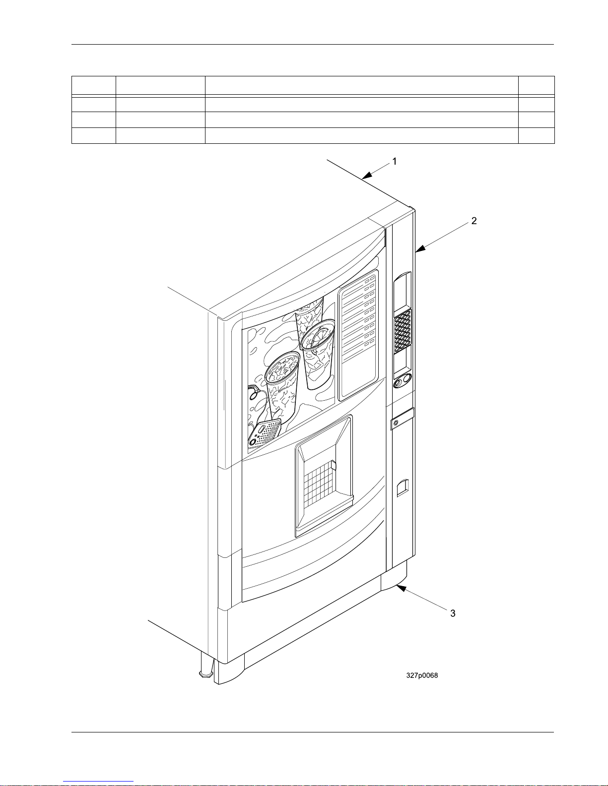
FIGURE 1: 328 MERCHANDISER
TABLE 1: 328 MERCHANDISER
INDEX PART NUMBER DESCRIPTION QTY
1-- CABINET ASSEMBLY (SEE TABLE 17 FOR DETAILS) 1
2-- DOOR ASSEMBLY (SEE TABLE 6 FOR DETAILS) 1
3-- BASE PLATE ASSEMBLY (SEE TABLE 18 FOR DETAILS) 1
Section A: Exterior of Door Cold Drink Center Parts Manual
3280033 2 August, 2003
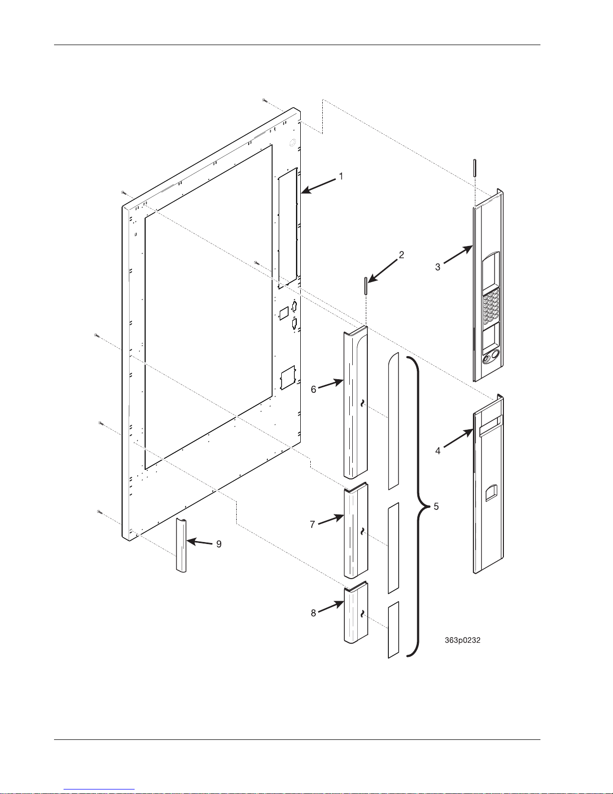
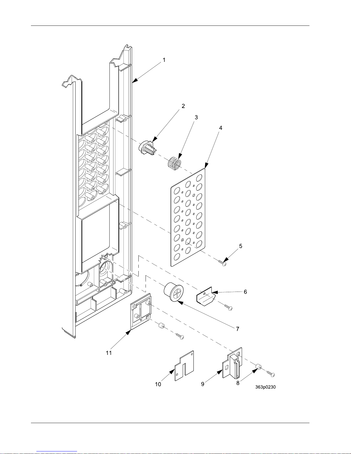
FIGURE 2: TRIM - MILLENNIA STYLE - PART 1 OF 3
Cold Drink Center Parts Manual Section A: Exterior of Door
August, 2003 3 3280033
TABLE 2: TRIM - MILLENNIA STYLE - PART 1 OF 3
INDEX PART NUMBER DESCRIPTION QTY
1 3282019 DOOR WELD ASSEMBLY - PAINTED 1
2 1572259 FILLER - GROOVE - SHORT 2
31572254 RIGHT PANEL MONETARY & BUTTON ASSEMBLY - A21 (327) 1
3632137 RIGHT PANEL MONETARY & BUTTON ASSEMBLY - A24 (328)
4 1572214 RIGHT HAND TRIM - LOWER - B 1
5 1572258 DECAL - DOOR TRIM VERTICAL ASSEMBLY 1
6 4552058 LEFT HAND TRIM - UPPER - C 1
7 4552059 LEFT HAND TRIM - MIDDLE - D 1
8 4552060 LEFT HAND TRIM - BOTTOM - E 1
9 1572267 TRIM - LOWER - DOOR SIDE - GRAY --
Section A: Exterior of Door Cold Drink Center Parts Manual
3280033 4 August, 2003
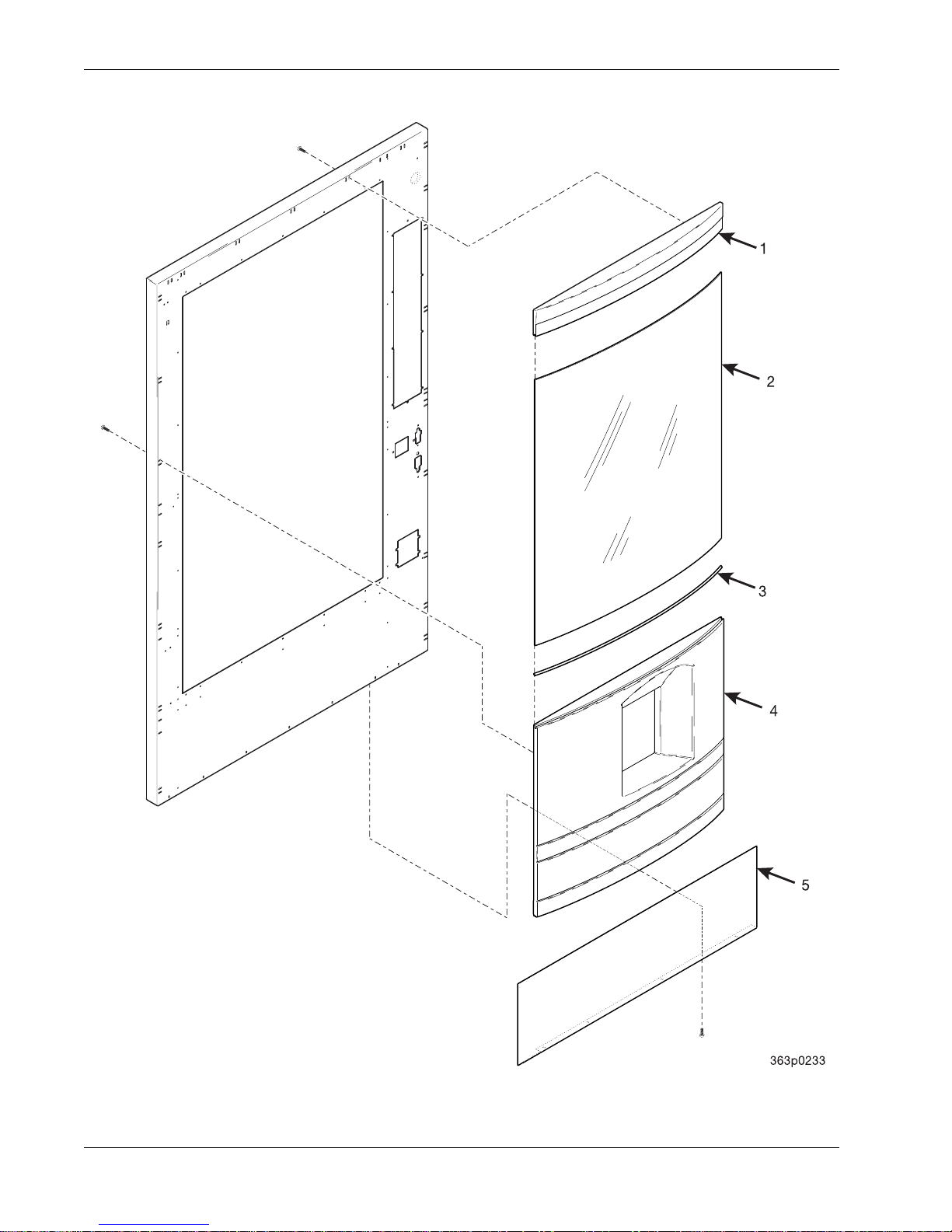
FIGURE 3: TRIM - MILLENNIA STYLE - PART 2 OF 3

Cold Drink Center Parts Manual Section A: Exterior of Door
August, 2003 5 3280033
TABLE 3: TRIM - MILLENNIA STYLE - PART 2 OF 3
INDEX PART NUMBER DESCRIPTION QTY
13632202 HORIZONTAL TRIM - TOP - 42" - H3 1
3632204 DECAL - TRIM HORIZONTAL - 42”
2 3632033 GLASS - CURVED FRONT - 42" TWIN 1
3 3632135 GASKET - GLASS 1
4 3632203 HORIZONTAL TRIM - 42" TWIN - R2 1
5 3632133 PANEL - BOTTOM - PAINTED 1
Section A: Exterior of Door Cold Drink Center Parts Manual
3280033 6 August, 2003
FIGURE 4: TRIM - MILLENNIA STYLE - PART 3 OF 3
Cold Drink Center Parts Manual Section A: Exterior of Door
August, 2003 7 3280033
Note: Model 327 uses a 21 key assembly
Model 328 uses a 24 key assembly
TABLE 4: TRIM - MILLENNIA STYLE - PART 3 OF 3
INDEX PART NUMBER DESCRIPTION QTY
-- 1572254 RIGHT PANEL MONETARY & BUTTON ASSEMBLY - A - 21 --
3632137 RIGHT PANEL MONETARY & BUTTON ASSEMBLY - A - 24
11572213 RIGHT HAND TRIM- UPPER - A - 21 1
3632114 RIGHT HAND TRIM - UPPER - A - 24
2 1572212 ARRAY - PUSH BUTTON SELECTION 1
3 1572224 SPRING - PUSH BUTTON 24
4 1572223 PLATE - STOP BUTTONS 1
5 1472454 SCREW-#6-20 X.31 PHIL.TRUSS 12
6 1572292 RETAINER - RETURN BUTTON 1
7 1572210 COIN RETURN BUTTON - A-2 1
8 2302053 SPACER CUP 4
9 1572323 EXTENSION - COIN INSERT 1
10 1472222 COIN BLOCK 1
11 1572209 COIN INSERT - A-1 1

Section A: Exterior of Door Cold Drink Center Parts Manual
3280033 8 August, 2003
FIGURE 5: TRIM - STANDARD STYLE

Cold Drink Center Parts Manual Section A: Exterior of Door
August, 2003 9 3280033
TABLE 5: TRIM - STANDARD STYLE
INDEX PART NUMBER DESCRIPTION QTY
1 -- PANEL - TOP (SEE TABLE 5A FOR DETAILS) 1
23632263 TRIM - DOOR - TOP - CLEAR 1
3632009 TRIM - DOOR - TOP - BLACK
3 3632011 TRIM - INSERT 3
4 3632010 TRIM - DOOR - HORIZONTAL - CLEAR 2
5 -- PANEL - RIGHT HAND (SEE TABLE 5B FOR DETAILS) 1
61302409 TRIM - DOOR - SIDE (CLEAR) 2
1452203 TRIM DOOR - SIDE - BLACK - IBM
7 -- PANEL - RIGHT CENTER (SEE TABLE 5C FOR DETAILS) 1
8 3152560 TRIM - VERTICAL 2
9 -- PANEL - BOTTOM (SEE TABLE 5D FOR DETAILS) 1
10 -- PANEL - LEFT CENTER (SEE TABLE 5F FOR DETAILS) 1
11 3632007 TRIM - HORIZONTAL - GLASS 1
3632132 TRIM - HORIZONTAL - GLASS
12 -- PANEL - LEFT (SEE TABLE 5E FOR DETAILS) 1

Section A: Exterior of Door Cold Drink Center Parts Manual
3280033 10 August, 2003
TABLE 5A: TOP TRIM PANELS - STANDARD STYLE
PART NUMBER DESCRIPTION
3632265 BISON BLACK
3632231 BLACK HAIRCELL
3632235 DOVE GREY
3632228 LAMINATE
3632012 PICA
3632227 PRESIDENTIAL WALNUT
3632236 SLATE
3632233 STERLING
3632229 TEAK
TABLE 5B: RIGHT HAND TRIM PANELS - STANDARD STYLE
PART NUMBER DESCRIPTION
6332137 BISON BLACK
6332103 BLACK HAIRCELL
6332105 BLACK PICA
6332111 DOVE GREY
6332113 LAMINATE
6332115 MOROCCO GREY
6332119 PEWTER
6332045 PORT AU PRINCE
6332122 PRESIDENTIAL WALNUT
6332124 SLATE
6332100 STERLING
6332126 TEAK
TABLE 5C: RIGHT CENTER TRIM PANELS - STANDARD STYLE
PART NUMBER DESCRIPTION
3632237 DOVE
3632015 STERLING
Cold Drink Center Parts Manual Section A: Exterior of Door
August, 2003 11 3280033
TABLE 5D: BOTTOM TRIM PANELS - STANDARD STYLE
PART NUMBER DESCRIPTION
3632242 BISON BLACK
3632243 BLACK HAIRCELL
3632244 BLACK PICA
3632247 DOVE GREY
3632248 LAMINATE
3632251 PRESIDENTIAL WALNUT
3632252 SLATE
3632253 TEAK
3632269 PICA - NO COIN
3632013 STERLING
TABLE 5E: LEFT HAND TRIM PANELS - STANDARD STYLE
PART NUMBER DESCRIPTION
6332138 BISON BLACK
6232241 BLACK HAIRCELL
6232311 BLACK PICA
6232072 DOVE GREY
6232192 LAMINATE
6232323 MOROCCO GREY
6232201 PEWTER
6332044 PORT AU PRINCE
6232019 PRESIDENTIAL WALNUT
6232225 SLATE
6232039 STERLING
6232180 TEAK
TABLE 5F: LEFT CENTER TRIM PANELS - STANDARD STYLE
PART NUMBER DESCRIPTION
3632256 DOVE
3632016 STERLING

Section A: Exterior of Door Cold Drink Center Parts Manual
3280033 12 August, 2003
FIGURE 6: DOOR ASSEMBLY - EXTERIOR
This manual suits for next models
1
Table of contents
Popular Beverage Dispenser manuals by other brands

Cornelius
Cornelius FCB Pinnacle installation instructions

La Sommeliere
La Sommeliere DVV22 manual

Grindmaster
Grindmaster Crathco G23-2B Specifications

Coca-Cola
Coca-Cola Freestyle 7000 user guide

Manitowoc
Manitowoc M-15 Installation & service guide

Napa Technology
Napa Technology Pristine PLUS CX user manual


