Cranesmart Systems LMI System User manual

Cranesmart Systems
LMI System
-
User Manual
May 11, 2015
Rev 9

1 Cranesmart LMI Version R9
The Cranesmart™LMI System
Congratulations!
“You have invested in the industry’s leading technology in crane safety equipment.”
This manual covers the installation and operation of all Cranesmart™ Load Moment Indicators (LMI).
For sales, service or assistance: (888) 562-3222 / 1 (780) 437-2986
An electronic copy of this manual is available at www.cranesmart.com in Adobe PDF format.
Load cell transmitter FCC compliance identification
NFBLAB123
Angle transducer FCC compliance identification
NFBLAB124
Anti-2-block transmitter FCC compliance identification
NFBLAB124
FCC Compliance: Please note - Changes or modifications not expressly approved by Cranesmart
Systems for FCC compliance could void the user‟s authority to operate the equipment.

2 Cranesmart LMI Version R9
Warranty
Cranesmart™ Systems warrants to the purchaser of each new Cranesmart™ System that any part thereof which proves
to be defective in material or workmanship within two (2) years from date of delivery will be repaired or replaced at no
charge if the system is returned to us in Edmonton, Alberta with all freight charges prepaid. If a performance problem
should occur, contact our offices in Edmonton, Alberta, Canada at (888) 562-3222 or (780) 437-2986.
This warranty does not cover defects resulting from accident, alteration, improper use, or failure of the purchaser to
follow normal operating procedures as outlined in this instruction manual and/or industry best practices.
PLEASE NOTE:
OPENING THE DISPLAY PANEL VOIDS THE WARRANTY.
NO COMPONENTS OF THE SYSTEM ARE TO BE SUBMERGED IN WATER.
THIS WARRANTY IS IN LIEU OF ANY WARRANTY OR MERCHANTABILITY AND OF ALL OTHER
WARRANTIES, EXPRESSED OR IMPLIED, ALL OF WHICH ARE HEREBY EXCLUDED.
Cranesmart™ Systems shall in no event be liable for any special, indirect, or consequential damages whatsoever and
neither assumes nor authorises any person to assume for it any other obligation or liability.

3 Cranesmart LMI Version R9
Important Safety Information
All of Cranesmart™ Systems‟ load cells and support hardware have been designed and tested to have a minimum 5 to 1
safety factor and to meet or exceed the guidelines, standards and certification requirements set forth by more than 30
legislative bodies world-wide including API, ABS, DNV, ASME and OSHA.
All Cranesmart™ load cells and support hardware are to be considered “Critical Path“components. Loads imposed on
these components should never exceed the maximum rated capacity shown on the load cell(s)/components. The rated
capacity applies only to uniform direct tension loading (straight-line pull). Off-axis loading, bending, side loading, two-
blocking and shock loads should be avoided. Damages caused by such situations are not covered by our warranty.
Inspection for damage, deterioration, cracks and corrosion on all load-bearing components should be conducted pre-
use, weekly, monthly, quarterly or annually, depending upon crane usage. Load bearing components showing damage,
deterioration, cracks or corrosion should be removed from service. If the crane is two-blocked or side loaded the load
cell and links should be visually inspected immediately. Continued use of damaged components may result in
catastrophic failure and personal injury.
Unless authorized by the factory in writing, modifications such as cutting, welding or permanently attaching other
material to any load cell, pin, link or part-thereof will void the warranty. Do not repair, alter, rework, or reshape any load
bearing component by welding, heating, grinding or bending. Do not engrave or stamp markings into the steel body of
the load cell as this may affect the integrity of the load cell, will void the warranty, and may result in a costly replacement
of the steel body.
Regular Inspections
We recommend that all load components regularly undergo routine visual inspection as noted above. We also
recommend that a qualified inspector, using industry standard techniques such as Ultrasonic Testing and/or Dye
Penetrate Testing, annually inspect the load components. These tests are to be performed in conjunction with the
inspection frequencies and guidelines as mandated by your applicable regulatory bodies.
IMPORTANT NOTE: Do not disassemble the load cell by removing the plastic covers during testing. Disassembly will
require the cell to be returned to the factory for re-calibration and testing.
If ANY issues are found please note the Cranesmart™ System serial number, contact our staff at 888-562-3222 or 780-
437-2986 and ask for the service department.

4 Cranesmart LMI Version R9
Table of Contents
INSTALLATION INSTRUCTIONS.................................................................................................................................... 10
LOAD CELL LINK INSTALLATION................................................................................................................................ 11
Male/Female load cell installation (7,500, 15,000 & 25,000 lbs).............................................................................. 11
Male/Female 7.5/15/25K Load Cell Link Placement Dead-end - for Multiple Parts-of-Line:............................. 12
Male/Female 7.5/15/25K Load Cell link Placement on Headache Ball - for Single Part-of-Line:...................... 13
Male/Male Flat Link Load Cell Installation (40,000, 50,000 or 80,000 lbs.)............................................................ 14
Sandwich Link Stabilization Pin –Male/Male flat link load cells only................................................................ 14
Male –Male 40/50/80K Load Cell Link Placement on Boom Tip Dead-end - for Multiple Parts-of-Line:........ 15
Male –Male 40/50/80K Load Cell Link Placement on headache Ball –for Single Part-of-Line:....................... 16
LOAD CELL BATTERY REPLACEMENT....................................................................................................................... 17
RADIO LINERIDER INSTALLATION.............................................................................................................................. 19
Radio Linerider Installation Overview....................................................................................................................... 19
Hydraulic Boom Linerider Installation Instructions................................................................................................... 20
Installation steps .................................................................................................................................................... 20
Lattice Boom Linerider Installation Instructions........................................................................................................ 21
Installation steps .................................................................................................................................................... 21
Installing The Wire Rope (Hoisting Cable) Through Linerider Assembly Instructions............................................ 23
Installation steps .................................................................................................................................................... 23
ANTI-2-BLOCK INSTALLATION..................................................................................................................................... 24
Counterweight............................................................................................................................................................. 25
BOOM ANGLE TRANSDUCER INSTALLATION.......................................................................................................... 26
WIND SPEED TRANSDUCER INSTALLATION............................................................................................................. 27

5 Cranesmart LMI Version R9
RADIO CABLE REEL WITH BOOM ANGLE MEASUREMENT.................................................................................. 28
Cable Reel Assembly.................................................................................................................................................. 28
Cable Reel Installation................................................................................................................................................ 29
Installation of Mounting Feet ................................................................................................................................ 29
Small Cable Reel Installation ................................................................................................................................ 30
Large Cable Reel Installation ................................................................................................................................ 31
Cable Reel Drum Installation ................................................................................................................................ 31
Installing the Guides and Anchor.......................................................................................................................... 32
Terminating the Cable at the Anchor .................................................................................................................... 33
LEVEL TRANSDUCER INSTALLATION INSTRUCTIONS.......................................................................................... 34
Installation Type A –Measuring Machine Tilt (Roll)................................................................................................ 34
Installation Type B –Measuring Grade and Super Elevation / Ship List (Roll) and Trim (Pitch)............................ 35
Level Transducer Error Messages .............................................................................................................................. 36
BATTERY REPLACEMENT FOR ANTI-2-BLOCK, ANGLE, CABLE REEL & LEVEL TRANSDUCERS............... 37
BOOM DIRECTION TRANSDUCER –BDT .................................................................................................................... 38
Mounting the BDT Bracket ........................................................................................................................................ 38
Tank Tags.................................................................................................................................................................... 38
DISPLAY PANEL INSTALLATION.................................................................................................................................. 40
Mounting the Display Panel ....................................................................................................................................... 40
Wiring the Display Panel............................................................................................................................................ 41
Alarm Shut-offs –The White Wire ............................................................................................................................ 41
Basic Wiring Diagram........................................................................................................................................... 42
Power Converters........................................................................................................................................................ 43
Hazardous Location Rated systems............................................................................................................................ 43
Junction Box ............................................................................................................................................................... 43

6 Cranesmart LMI Version R9
Junction Box Wiring Diagram............................................................................................................................... 44
Alarm Hub .................................................................................................................................................................. 45
Alarm Hub Wiring Diagram.................................................................................................................................. 46
Antenna Installation.................................................................................................................................................... 47
Antenna types ........................................................................................................................................................ 47
Outside Operator Cab OR no Cab on Crane ......................................................................................................... 48
Inside Operator Cab............................................................................................................................................... 49
Marine Installation................................................................................................................................................. 50
Shut-off Bypass Plug .................................................................................................................................................. 51
DISPLAY PANEL OPERATIONS...................................................................................................................................... 52
System Start-up........................................................................................................................................................... 52
To Accept the Current Configuration.................................................................................................................... 53
To Change the Display Panel Configuration......................................................................................................... 53
Quick Winch Switching.............................................................................................................................................. 54
To View the Auxiliary Winches............................................................................................................................ 54
To Accept the New Winch Configuration............................................................................................................. 56
Panel Button Functions............................................................................................................................................... 57
Menu Navigation ........................................................................................................................................................ 58
Secondary Operating Screen Navigation Bar........................................................................................................ 58
Tare Out Function.................................................................................................................................................. 58
Setup Menus .......................................................................................................................................................... 59
OPERATOR PERMISSION LEVEL................................................................................................................................... 60
Configure Menu.......................................................................................................................................................... 61
Select Winch and POL (Parts-of-line)................................................................................................................... 61
Limits Menu................................................................................................................................................................ 61
Load Limits............................................................................................................................................................ 61
Angle Limits.......................................................................................................................................................... 62

7 Cranesmart LMI Version R9
Tip Height Limits .................................................................................................................................................. 62
Radius Limits......................................................................................................................................................... 62
Level Transducer Limits........................................................................................................................................ 63
Wind Limits........................................................................................................................................................... 63
System Menu .............................................................................................................................................................. 64
About ..................................................................................................................................................................... 64
LCD Contrast......................................................................................................................................................... 64
Permissions............................................................................................................................................................ 64
Diagnostic Menu......................................................................................................................................................... 65
Signals.................................................................................................................................................................... 65
Panel Relay............................................................................................................................................................ 65
Viewer.................................................................................................................................................................... 65
Cable Reel.............................................................................................................................................................. 66
SUPERVISOR PERMISSION LEVEL................................................................................................................................ 67
Permissions Level....................................................................................................................................................... 68
To Set the Permission Level.................................................................................................................................. 68
To Exit the Setup Menu......................................................................................................................................... 68
Calibration Menu........................................................................................................................................................ 69
Load Cell Calibration ............................................................................................................................................ 69
Boom Angle Indicator Calibration ........................................................................................................................ 71
Level Transducer Calibration................................................................................................................................ 71
Cable Reel Calibration........................................................................................................................................... 72
Options Menu.............................................................................................................................................................. 73
Limits Lock............................................................................................................................................................ 73
Bypass button......................................................................................................................................................... 73
Ext Relay (Output for Shutoff/Horn/Indicator)..................................................................................................... 73
Config Lock........................................................................................................................................................... 74
Language................................................................................................................................................................ 75
Units....................................................................................................................................................................... 75

8 Cranesmart LMI Version R9
BDT Default .......................................................................................................................................................... 75
Basket Capacity ..................................................................................................................................................... 76
System Menu .............................................................................................................................................................. 76
About ..................................................................................................................................................................... 76
LCD Contrast......................................................................................................................................................... 76
Permissions............................................................................................................................................................ 77
Restricted............................................................................................................................................................... 77
Clock...................................................................................................................................................................... 77
Checksum Repair................................................................................................................................................... 77
Display Timer........................................................................................................................................................ 78
Supervisor Enable/Disable Menu ............................................................................................................................... 78
Logger Menu............................................................................................................................................................... 78
Download............................................................................................................................................................... 78
PIN Codes.............................................................................................................................................................. 79
PIN Login .............................................................................................................................................................. 79
DISPLAY PANEL –OPERATING SCREENS................................................................................................................... 80
Primary Operating Screen ..................................................................................................................................... 80
Secondary Operating Screen ................................................................................................................................. 80
Limits Screen......................................................................................................................................................... 82
Signal Strength Screen........................................................................................................................................... 83
Info Screen............................................................................................................................................................. 84
DISPLAY PANEL –ALARMS ........................................................................................................................................... 85
Alarm Codes ............................................................................................................................................................... 86
Function Shut Offs...................................................................................................................................................... 89
TECHNICAL SPECIFICATIONS ....................................................................................................................................... 90
7,500lb single line pull load cell................................................................................................................................. 90
15,000 single line pull load cell.................................................................................................................................. 91

9 Cranesmart LMI Version R9
25,000lb single line pull load cell............................................................................................................................... 92
40,000lb single line pull load cell............................................................................................................................... 93
50,000lb single line pull load cell............................................................................................................................... 94
80,000lb single line pull load cell............................................................................................................................... 95
Anti-2-Block Switch................................................................................................................................................... 96
Boom Angle Transducer............................................................................................................................................. 97
Display Panel.............................................................................................................................................................. 98
Alarm Hub .................................................................................................................................................................. 99
Wind Speed Transducer............................................................................................................................................ 100

10 Cranesmart LMI Version R9
Installation Instructions
Guidelines
- Read these instructions before beginning installation procedures.
- If the power available is not 12 to 24VDC (28VDC maximum) Cranesmart™ Systems can supply the
necessary converters. Please call our service department at (888) 562-3222 or (780) 437-2986.
Have the necessary tools available.
Mount the transducers - Load Cell, Angle transducer, A-2-B switch, etc.
Mount the Panel, Alarm Hub and Antenna.
Test the system.
Tools Required
Man basket if the boom cannot be lowered–to reach the boom, rooster sheave and/or jib
Pliers –for removing and bending cotter pins.
Electric drill with bits.
Welder not required for LOAD CELL installation –for attaching weld plate to boom/jib tips –if installing A2B or angle systems.
Wire crimping tools –for the display panel power and ground connections.
Screw drivers and/or socket set.
Anti-seize compound for bolts and threaded pins so that the components can be disassembled and/or removed if necessary.
NOTE:
When a Cranesmart™ system is programmed for use with an Alarm Hub, the Alarm Hub will need to be present as power to the display panel is
routed through the alarm hub. If the Alarm Hub is damaged or missing and the panel is powered, an error condition will be present on the display
panel.

11 Cranesmart LMI Version R9
Load Cell Link Installation: “Male to Female” load cell form (7,500, 15,000 & 25,000 lbs)
(Blue = Main Line, Yellow = Aux. 1 Line, Orange = Aux. 2 Line)
Refer to the following two illustrations for the correct installation of the load cell(s):
1. Even Parts of Line: Pin the load cell between the wire rope socket (becket) and the dead end on the boom of the crane (see second
illustration)
2. Odd Parts of Line: Pin the load cell between the wire rope socket (becket) and the headache ball.
3. If an Aux.2 load cell link, pin to the auxiliary line from the rooster sheave on the crane‟s boom tip.

12 Cranesmart LMI Version R9
Load Cell Link Installation: “Male to Female” form (Dead-End / Multiple Parts-of-Line)
1. Pin the load cell link between the wire rope (wedge) socket and the dead end as illustrated below.
2. Your system is calibrated at the factory.
3. If you have any questions please call our sales department at (888) 562-3222 or (780) 437-2986.
NOTE:
Ensure the load cell does not contact the boom or rigging at any angle when pinned in place.

13 Cranesmart LMI Version R9
Male/Female 7.5/15/25K Load Cell link Placement on Headache Ball - for Single Part-of-Line:
Pin the load cell link between the wire rope (wedge) socket and the “Headache Ball” or hook block as illustrated below.
Your system is factory calibrated. If you have any questions please call our sales department at (888) 562-3222 or
(780) 437-2986.
NOTE:
Custom links are available, if necessary, to help fit the load cell on the ball. Please call for assistance.

14 Cranesmart LMI Version R9
Male/Male Flat Link Load Cell Installation (40,000, 50,000 or 80,000 lbs.)
(Blue = Main, Yellow = Aux. 1 Winch, Orange = Aux. 2 Winch)
Sandwich Link Stabilization Pin –Male/Male flat link load cells only
The Sandwich Link Stabilization Pin prevents the sandwich link from folding against, and damaging the load cell when
the headache ball or hook block is laid on the ground or during a two-blocking. Also ensure that it is securely in place.
Ensure that the locking threaded centre pin and the stabilization pins are located in place as illustrated below.

15 Cranesmart LMI Version R9
Male –Male 40/50/80K Load Cell Link Placement on Boom Tip Dead-end - for Multiple Parts-of-Line:
The drawings below show the standard Sandwich Link installation and the optional 24” long Sandwich Link installation.
Use the Sandwich Links to pin the load cell link between the wire rope socket (becket) and the dead end boom tip as
illustrated below. Place the locking threaded centre pin (important) and the stabilization pin as illustrated below.
Your system is factory calibrated. If you have any questions please call our sales department at (888) 562-3222 or
(780) 437-2986.
NOTE:
Ensure the load cell does not contact the boom or rigging at any angle when pinned in place.

16 Cranesmart LMI Version R9
Male –Male 40/50/80K Load Cell Link Placement on headache Ball –for Single Part-of-Line:
Pin the load cell link between the wire rope (wedge) socket and the “Headache Ball” or hook block as illustrated below.
Place the locking threaded centre pin and the stabilization pin as illustrated below.
Your system is factory calibrated. If you have any questions please call our sales department at (888) 562-3222 or
(780) 437-2986.

17 Cranesmart LMI Version R9
Load Cell Battery Replacement
The display panel will indicate a low battery for approximately three (3) weeks before the battery fails.
Starting for systems sold during and after February 2008, Cranesmart™ Systems will supply replacement power cells for
our transmitters for the cost of freight shipping (customers are responsible for any incurred taxes/duties).
Before replacing the batteries call the service department at (888) 562-3222 or (780) 437-2986. Once you have verified
that it is a dead battery follow the steps below.
Please have the serial number of your system handy before calling for replacement batteries or to ask for
technical assistance. You can find the serial number on either the display panel or the load cell itself.
Tools and Equipment for battery replacement:
Battery replacement kit contains:
One 3.6 volt Lithium Ion D-cell battery
Two O-rings –(one for a 7.5/15/25K load cell, one for a 40K and larger load cell)
One 6g packet of Silicone Grease (Dow corning 111 or similar)
One 5/32” Allen key
The Kit also contains the following:
Two battery cover gaskets –(one for a 7.5/15/25K load cell, one for a 40K and larger load cell)
One tube of RTV Silicone Sealant (Dow corning 734 or similar)
These parts are designed for use with the older gasket sealed load cells and are not to be used with o-ring sealed load cells.
NOTE:
SAFT 33600 3.6V Lithium power cells may also be available from local sources. Ensure that you take the existing battery with you if possible for
correct size matching. Other manufacturer‟s may not follow the SAFT sizing conventions.
If you purchase your own battery you will also need to reuse the o-ring. Please ensure that you use grease, as per the instructions below, when
installing the o-ring.

18 Cranesmart LMI Version R9
Locate the four exposed hex bolts on the battery compartment side of the Load Cell. If the holes are filled with silicone
you are on the transmitter side of the Load Cell. Do not open this side, it has no user serviceable parts. Your warranty
will be Void if the Transmitter Electronics section has been opened.
1. Remove the load cell from the crane.
2. Use the Allen key to remove the four hex bolts.
3. Remove battery from clip (ensure you do not break the red polarisation tab).
4. Install the new Battery, (positive „+‟ to red polarisation tab).
5. Remove the old o-ring from the aluminum plate and discard.
6. Grease the proper replacement o-ring with your fingers using a portion of the silicone grease supplied with the kit.
7. Install the new greased o-ring into the groove on the aluminum plate. Apply the remaining grease liberally covering the o-ring and groove.
As mentioned above, Do Not use the RTV silicone sealant it is for the older gasket style load cell.
8. Place the plastic cover over the Battery pack taking care not to pinch the battery wires.
9. Replace the screws and fully tighten the hex bolts. Some grease may squeeze out depending on the amount grease applied.
10. Clean off any excess grease.
11. Re-install the load cell to test its operation.
Do not use a power drill or power screwdriver to remove or tighten the bolts, you may damage the threads on
the aluminum plate.

19 Cranesmart LMI Version R9
Radio Linerider Installation
The linerider installation will depend on the type of boom. Please read and follow the applicable instructions for
hydraulic or lattice style booms.
Radio Linerider Installation Overview
The linerider is attached to a swing arm mounting bracket (included with kit) as shown in the illustration below.
The swing arm assembly has four joints:
1. Vertical movement at the attachment point to the linerider.
2. Horizontal movement of the swing arm.
3. Vertical movement of the swing arm.
4. Swivels horizontally around the mounting bolt.
Table of contents
Popular Lifting System manuals by other brands

PLATFORM BASKET
PLATFORM BASKET SPIDER 18.90 PRO Use & maintenance manual
stellar labs
stellar labs Slider40 owner's manual

Bear
Bear 30-MR600 Installation and service manual

Harmar Mobility
Harmar Mobility AL215 Axis I Installation & owner's manual

Aqua Creek Products
Aqua Creek Products Revolution Deep Draft Lift manual
Nussbaum
Nussbaum TSK 8000 Operating Manual and Inspection Book
ATT NUSSBAUM
ATT NUSSBAUM COMBI LIFT 4.40 S Operating manual, Inspection book

Sealey
Sealey MT500 instructions
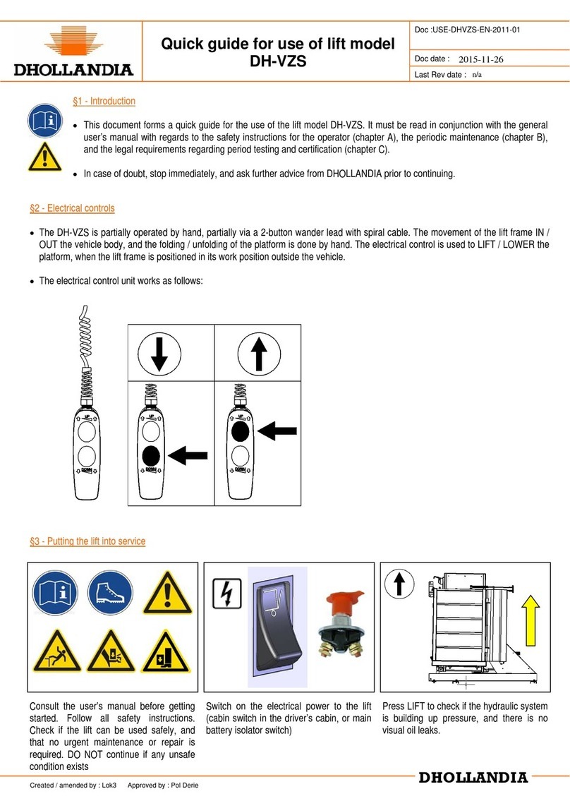
Dhollandia
Dhollandia DH-VZS Quick guide for use

Lippert
Lippert Schwintek installation manual

PFlow Industries
PFlow Industries F Series owner's manual
MONDELIN
MONDELIN LEVPANO I Instruction and maintenance manual
