EKKO Walkie EB16EA User manual

2
Specification
Walkie Electric Stacker
EB16EA/EA16EAS(with side shifter )

3
Introduction
In order to meet the needs of the national environmental protection request, To
reduce industrial pollution and improve productivity, we develop new series of
EB16EA on the basis of absorption of the advantages of domestic & overseas
battery Electric Stacker ,they are especially suitable for cargo loading and
unloading, handling, stacking, etc. for food, bank, light textile, station, port,
logistics and other enterprises.
The Stacker adopts advanced structures such as Good view lifting system, EPS
system(Electric Power Steering system), and new AC controller. It is equipped with
high-quality motor, traction battery and high-power pumping station motor.
Therefore, it has the characteristics of superior performance, convenient
operation, wide field of view, flexible steering, reliable braking, good power, low
noise, no pollution, and beautiful appearance.
This manual describes the technical parameters of the Electric Stacker, working
principle and operation, maintenance, and other aspects. It can help operators use
the Electric Stacker more reasonable, make its maximum effect.
It is hoped that Operator strictly abide the regulations and the precautions in this
manual when using the Electric Stacker .Carefully use them so that your Electric
stacker can be in the best working condition for long period of time to maximize
it’s effectiveness. And create better economic benefits.

4
The Statement
Our company production model EB16EA /EB16EAS Electric stacker is a special
motor vehicle used in factory ,tourist attractions ,amusement places which is
specified by “special equipment safety supervision regulations” .

5
CONTENTS
Introduction ...................................................................................................3
The Statement................................................................................................4
1.General Introduction ...............................................................................7
2、Proper use ................................................................................................8
3.Introduce of the product.........................................................................9
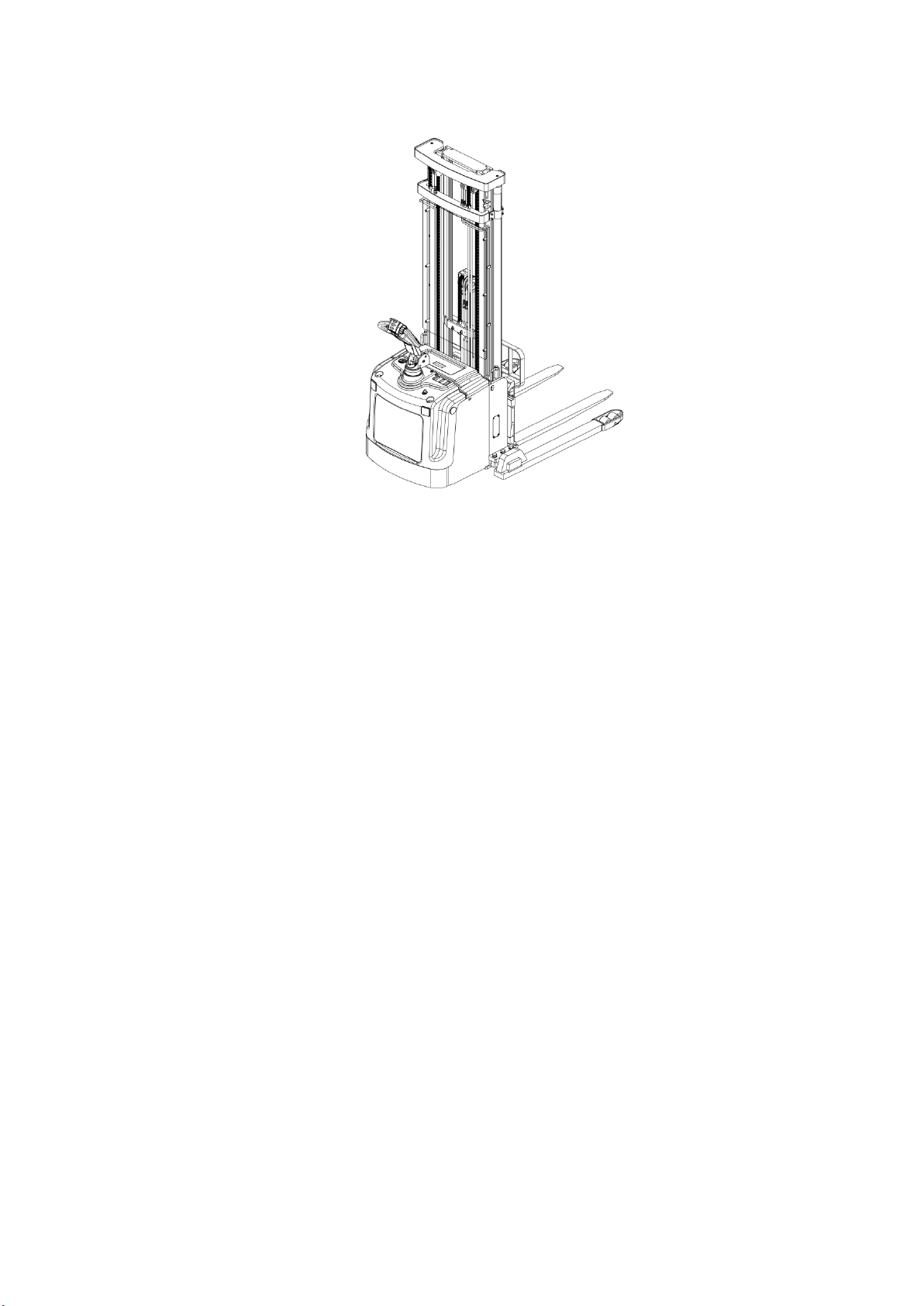
3.1Product overview ............................................................................................................................................9
3.2Model Parameter...........................................................................................................................................10
3.3Safety Operation and warning label description.............................................................................12
3.4Nameplate ......................................................................................................................................................12
4.Safety Caution.......................................................................................... 13
5.Test run,Transportation,Outage ....................................................... 14
5.1Test run .............................................................................................................................................................14
5.2Lifting & Transportation............................................................................................................................14
5.3Outage................................................................................................................................................................14
6.Routine Inspection................................................................................. 15
7. The Schematic diagram of Operating Mechanism...................... 16
8.Operating specification........................................................................ 16
8.1Parking ..............................................................................................................................................................16
8.2Loading capacity Graph..............................................................................................................................17
8.3Lifting up/Lowering down .......................................................................................................................17
8.4Traveling...........................................................................................................................................................18
8.5Steering .............................................................................................................................................................19
8.6Braking..............................................................................................................................................................19
8.7Brake structure &Brake Schematic.......................................................................................................20
8.8Trouble........................................................................................................................................................... 200

6
8.9Emergency situations..................................................................................................................................20
9.Changing and Replacement for battery .......................................... 21
9.1Charging............................................................................................................................................................21
9.2Battery display...............................................................................................................................................22
9.3Replacement ...................................................................................................................................................22
10.Maintain Introduction........................................................................ 23
10.1Maintenance list..........................................................................................................................................23
10.2Lubrication point........................................................................................................................................25
10.3Check and refill hydraulic oil.................................................................................................................25
10.4Check the electrical fuse..........................................................................................................................25
11.Trouble shooting.................................................................................. 26
12. Electrical Schematic diagram ......................................................... 27
13.Hydraulic Schematic diagram ......................................................... 28
14.After-sales service............................................................................... 29

7
1.The General Introduction
EB16EA Electric Stacker uses a battery as the power source and AC motor as
power to drive the truck through gear transmission, The lifting of the fork is driven
by the AC motor hydraulic drive to push the cylinder to lift and lower the cargo. As
the truck Electric motor for Lifting and Driving .Then it has the characteristics of
labor saving, high efficiency, stable cargo operation, simple operation, safety and
reliability, low noise and no pollution.
The device is suitable for Stacking & Handling cargo on firm ,flat floors
The service environment:
a. Altitude does not exceed 1200m.
b. Indoor room temperature at +5℃ to +40℃.
c. When environment temperature at +40℃,the relative humidity can’t over
50%,at low temperature ,allow bigger relative humidity
d. Firm, Flat ground 。
e. It is forbidden to use this car in corrosive environment such as flammable
and explosive or acid base
Due to the continuous improvement of the product, the manufacturer reserves the right to
change the design and specifications of the product without prior notice. If you want to know
the latest product parameters, please contact us. Note: All parameters herein are subject to
the date of publication of the manual

8
2. Proper use
Please using the Electric Stacker according to this specification.
This is a walkie type electric stacker with autonomous control , lifting and
lowering is controlled by the handle button.
Improper use can cause personal injury or machine damage. Operators or
operating companies need to ensure proper using,
The Truck needs to be used on a firm ,flat ,intact surface and suitable
surface ,the truck is designed for indoor use at room temperature from+5°C to
+40°C
Use under light load without using permanent barriers or pits ,It is forbidden
to operate on the slopes .During Operation ,The goods must be placed
approximately at the center of the truck’s load center
Lifting or Carrying people is strictly prohibited ,if carried goods .The goods
must fall on the lifting point 。
It is prohibited to use this truck on lifting or loading ramps.
The rated capacity is marked on the capacity label or nameplate. And the
operator must pay attention to the warming signs and safety instructions.
Operating lighting must be at least 50LUX
Modification
Any modification that may affect the truck rated capacity, stability, and safety
operations must be approved in advance by the Truck’s original manufacturer or
Its authorized Manufacturer or its successor. This includes the effects of changes
such as Braking ,steering ,Visibility, and the addition of removable accessories.
After the manufacturer or its successor approves the modification or change ,The
capacity name plate ,Label, identification marks, operation and maintenance
manual must be changed accordingly
Truck damage caused by not following Instruction will lose its warranty.

9
3.Introduce of the product
3.1Overview of main components
Figure 1 main components
No.
Description
No.
Description
1
Operating handle
5
Key switch
2
Electricity meter
6
Main frame assembly
3
Emergency stop switch
7
Door Frame Assembly
4
Cover

10
3.2Model parameters
Fig 2 Schematic diagram of the stacker

11
Main technical parameter list
Mode
EB16EA
EB16EA+C(With side
shifter
Drive type
Electric
Electric
Type of operation
Walkie type
Walkie type
Load Capacity
Q (LBS)
4400
4400
Load center
x (Inch)
23.62
23.62
Distance between fork
backrest and front wheel
c (Inch)
32.08
30.59
Wheelbase
y (Inch)
63.78
63.78
Service Weight(with
battery)
Q (LBS)
3542
3680
Tire material
PU
PU
Driving wheel size
Φ×w(Inch
)
Ö9.84×2.95
Ö9.84×2.95
Bearing wheel size
Φ×w(Inch
)
Ö3.15×2.76
Ö3.15×2.76
Balance wheel size
Ö×w(Inch
)
Ö4.53×2.17
Ö4.53×2.17
No of Driving wheel, Balance
wheel/Bearing
wheel(X=Driving wheel
1x+2/4
1x+2/4
Front wheelbase
b10 (Inch)
22.83
22.83
Rear wheelbase
b11 (Inch)
42.91-56.69
42.91-56.69
Lowered mast height
h1 (Inch)
98.03
98.03
Free lift height
h2 (Inch)
64.57
61.25
Lift height
h3 (Inch)
216.54
216.54
Extended mast height
h4 (Inch)
251.18
253.54
The height of handle in the
operation position
h14(Inch)
39.76/57.08
39.76/57.08
Lowered fork height
h13 (Inch)
2.36
2.17
Overall Length
l1 (Inch)
81.65
80
Body Length
l2 (Inch)
36.37
37.87
Overall Width
b1/ b2
(Inch)
47.8-61.58/31.81
47.8-61.58/31.81
Fork Size
s/e/l
(Inch)
1.58/4.72/45.28
1.58/4.72/45.27
Fork Width
b5 (Inch)
9.84-31.5
15.2-24.65
Ground clearance under mast
m2 (Inch)
1.02
1.02
Aisle width for pallets
1000*1200 crossways
Ast (Inch)
101.77-107.87
102.76
Turing Radius
Wa (Inch)
69.57
69.57
Driving Speed,load/unload
(km/h)
5.2/5.5
5.2/5.5
Lifting Speed load/unload
(mm/s)
95/160
95/160
Lowered Speed load/unload
(mm/s)
130/110
130/110
Maximum gradeability
load/unload
(%)
5 /.8
5 /.8
Brake Type
Electromagnetic
brake
Electromagnetic
brake
Driving Motor
(kW)
3
3
Lift Motor
(kW)
3
3
Battery,according to DIN
43531/35/36 A,B,C,no
no
no
Battery voltage/rate capacity
(V/Ah)
24/210
24/210
Battery Weight(±5%)
(LBS)
462
462
Type of drive control
AC
AC
Noise level
(dB(A))
70
70

12
3.3Safe operation and warning labels
A. Lifting position
B. It is forbidden to stand on /off the fork
C. Four kinds of mis operations are prohibited
D. .Loading capacity graph
E. Warning label
F. Name plate
Figure 3 label diagram
3.4Nameplate
Fig4,Nameplate

13
4.Safety Caution
Please don’t
• When travel outdoor, The stacking operation makes the lifting height of the cargo
higher than the lifting point
• Place the foot or hand under or into the lifting mechanism
• Allow Non-Operators to stand in front of or behind the truck during moving or
lifting / lowering
• Overload
• Put your foot on the front of the wheel may cause injury
• When lifting person, they may fall and cause serious injury
• Push and pull cargo
• Use the car on the slope
• Use the car without Shielding panel
• Side load or tail load ,the cargo must be evenly distributed on the fork
• Use this car to load unstable ,unbalanced cargo
• Use this car without the manufacturer’s written consent
• The uplifted cargo will become unstable because of wind .Don’t lift the cargo in
windy condition
Observing different ground condition during driving .The cargo may fall down, or the car may
lose control ,please check the loading situation frequently, If the cargo becomes unstable .Stop the
operation of the truck immediately . When the cargo slide or slide off the truck, Stop the car by
pressing emergency stop switch .Please refer to Chapter 10 for any truck Trouble .Maintain
according to regular inspection. The forklift is not waterproof, Please use it in dry environment.
Continuous operation for a long time may damage the power box ,please stop operating when
Hydraulic oil temperature is too high .
• The operator should put on safety shoes when operating the forklift
• The car is suitable for indoor use in temperature from +5°C to 40°C
• Operating lighting must be at least 50LUX
• Don’t use the car on the slope
• In order to prevent sudden movement of the car when the car is not operated
!
!

14
(such as caused by others),turn off the car power and remove the key when not
operating
5.Test run, Transportation, Outage
5.1Test run
Table 3 test data
Model
EB16EAS
EB16EA
Packing weight(lbs.)
3680
3542
Lifting height(Inch)
216.54
216.54
Size(Inch)
80*47.8*98.036
81.65*47.8*98.03
After receiving our new forklift or when it needs to be retest please with process with
following steps before (the first )operation of the forklift :
• Check if all parts are included .and there is no damage
• Battery installation and charging (refer to Chapter 9)
• Carry out daily inspection and machine function inspection
5.2Lifting & Transportation
Remove the cargo during transportation ,Lowered the
fork to the lowest position And according to Figure 5 Safety
fixed the car with special lifting equipment
Lifting
Use Special Crane and lifting equipment
Don’t stand under shaking cargo
Don’t enter the dangerous area when rising
Parking the truck safely,and bind the truck as figure 5 Shows
Lifting the truck to the destination ,Before Moving lifting
equipment please safety Fixed the car ,
The rope point can refer to figure 6
Transportation
The Truck should be firmly fixed on the truck during transportation
Lowered fork and parking the truck safety
As figure 6 shows Use the special binding belt to fix the tow big ribs of the car .And fixed
other side on the carrier
5.3Outage
When Storage remove the cargo and lowered the fork to lowest position. Grease all
lubrication points mentioned in this manual (check regularly)to prevent rust and dust.
!
Fig 5 Lifting Point
Fig6 Fixed Point

15
Remove the battery and check the truck to ensure no extrusion during storage.
When the car finally out of service ,send the car to designated recycling
company .According to regulations ,Oil, Batteries and electronic components must be
recycled .
6.Routine Inspection
This Chapter Describes check the car before using
Routine inspection can effectively find out the defect or error of this car. The following
points should be checked before operation.
Remove the cargo ,Lowered the fork. Please don’t use the car if there is any Problem.
• Check for scratches ,Deformation .or Cracks
• Check if the cylinder leaks of oil
• check running condition of the car
• Check if the chain or roller damage or corrosion
• Check if the wheels can move smoothly
• Press the emergency stop button to check the emergency brake function
• Check the Buzzer
• Check that all bolts and nuts are tightened
• Check the function of Key switch
• Visually Check for any damaged tube or wires
• If the car with Protective barrier .Check for damage and correct installation.
7.The Schematic diagram of Operating Mechanism
!

16
Fig 7 Operating console Fig 8 Key Switch
P.S.::Position of Emergency stop switch and Electricity meter is shown in fig 1.
8.Operating specification
Please follow the warning and safety instructions before operating the car (see as
chapter 3)
Please Ensure that cargo or other equipment will not lead to poor visibility before
operating the car
Ensure cargo level and stable placed .And conduct daily inspection .Insert the key into
the key Switch(Figure 8),Turn the key clockwise to “ON” position. Before finally inserting
the key switch,The emergency stop switch1.3(Figure 1) must be carefully pulled up.
Press the horn button(as figure7 .4)to start the buzzer
8.1Parking
Pls Don’t Park on the ramp
The car is equipped with an electromagnetic error protection Parking and Parking brake
Please always lower the forks completely and drive the car to a safe area. Turn the key
counterclockwise to the OFF position and pull out the key
!
!

17
8.2Loading capacity Graph
The loading capacity Graph shows a given load center c [Inch] and a car with
horizontal load ,the maximum load capacity Q [LBS] In the corresponding lifting height of
the truck H [Inch]
8.3Lifting up/Lowering down
Pls don’t overload, The related capacity is 1000KG/1600KG/2000KG .Only increase
the load capacity allowed by the load capacity graph
Please lower the fork completely on the leg during driving .Then press lift up
button(Figure 7.1)until reach your desired height .
If the goods is on the shelf when lowering down, Remove the truck carefully with the pallet
rack or move the truck off the shelf separately ,Then press Lower down key(Figure7.1)
Lower the cargo until the fork left the pallet rack .then carefully drive the car away from
Fig 9 loading capacity graph For EB16EA
!

18
Figure11,Operating Direction
the cargo
8.4Traveling
Only drive on the slope when the cargo is facing up
Don’t drive on the slope in excess the specified specifications .
Only can driving when the fork falls to the lifting point (<300mm)
⚫Turn the inserted key to the “open”position(Figure 8),Then pull up the
emergency stop switch (Figure 7.4), to start the truck.
⚫Move the handle to the operating area(‘F’figure 13).Turn the accelerator
button
!
Figure 10

19
to the forward direction‘Fw”or backward direction‘Bw’(Figure 11)
⚫Control the driving speed by carefully moving the button (fig.7.2)until reach your
desired speed .If you move the accelerator button back to the middle position,
the controller will slow down the truck until it stops. If the truck stops, the
parking brake starts to work.
⚫Drive the car carefully to the destination, Observe the road situation and adjust
the speed with the travel switch button
8.5Steering
The car with EPS steering system, Be careful when operating.
Steering the car by turning the handle to the left or the right
8.6Braking
Braking performance depends on road conditions and the loading conditions of car
The brake function can be activated in the following ways :
⚫By moving the accelerator (figure 7.2) to the “0)position or release the button,
Regenerative braking is activated and the truck brakes until it stops .
⚫By moving the accelerator (figure 7.2) directly from the drive direction to the
opposite direction., the truck regenerates braking until it starts driving in the
opposite direction
⚫The truck brakes if the handle moves up and down to the braking zone(‘B’).If
release the handle, it will automatically moves to the upper braking zone(‘B’)
and the car brakes until it stops
Emergency reverse button(figure 7.3)prevents the operator from being squeezed.
And if this button is activated ,the car slows down /or begins to travel backwards
(‘Bw’)and then stops. If the handle is in the operating area and the truck is
not moving .consider that this button still works for this situation
8.7Brake structure &Brake Schematic
!

20
Braking principle:as figure12 shows including :Brake by
magnetic yoke assembly 6、Magnet exciting coil 7、Spring 2、
brake disc 5、Armature 1、Geared sleeve 4、Mounting screw
3 .The brake is mounted on the end cap of the motor ,and the
mounting screw is adjusted to the specified air gap value. The
gear sleeve is fixed on the shaft .The external teeth cooperate
with the internal teeth of the brake disc. And the torque is
transmitted during operation. Then the brake disc can move
axially on the gear sleeve .
When Magnet exciting coil 7 of brake is energized .the coil
produces a magnetic field that caused the armature 1 draw toward the magnetic yoke
assembly 6.Armature 1 detached from the brake disc 5(Release).Then the motor drive
shaft with brake disc 5 start and operate normally. When Magnet exciting coil 7 is de-
energized., The magnetic flux disappears .Armature 1 is released .and spring 2 process
armature 1,then the friction plate on the brake disc is pressed to generate frictional force
for braking purposes
8.8Trouble
If there is any error or the car is not operate,Stop using and press the emergency stop
switch(Figure 1.7).Parking the car in safe area if possible .Turn the key counterclockwise
and remove the key(figure 8).Notify the manager or contact your after-sales service staff
immediately .Use a special towing equipment /lifting equipment to pull the truck out of
the operating area if necessary .
8.9Emergency situations
Keep a safe distance in an emergency situation or the car is turned over. Press the
emergency stop switch(Figure 1.7) and all electrical functions will stop.
Figure12 brake schematic

21
9.Changing and Replacement for battery
⚫Only Qualified personnel are allowed to repair or recharge the
battery .Please be sure to follow this manual and battery manufacturer’s
instructions.
⚫The battery is Lead-Acid battery
⚫Battery recycling is subject to national regulations .Please follow these
rules .
⚫When handling batteries .Don’t use open flame which my cause gas
explosion.
⚫Don’t place flammable materials and work equipment that may generate
sparks within a distance of at least 2M around the forklift that needs to
be recharged
⚫It is forbidden to burn materials or burn liquid in the charging area of
the battery. It is strictly forbidden to smoke. The area must be well
ventilated.
⚫Parking the car safely before you start charging ,installing /replacing the
battery
⚫Before finishing the repairing .please make sure that all cables are
connected and there is no interference to the other part of car .
For standard batteries, this model is equipped with the following lead acid battery
models:
1PC 2PZS/24V/210AH/790X210X570(LXWXH)
Only lead-acid batteries are allowed
The battery weight has a certain influence on car operation .Please
consider the max working temperature of the battery.
9.1Replacement
Park the car safely, Move the Mast forward to the appropriate distance,. Turn off the car
by key(Figure8) and press the emergency stop switch(Figure 7.4) to open the battery
!
!
Other manuals for Walkie EB16EA
1
This manual suits for next models
1
Table of contents
Other EKKO Lifting System manuals
Popular Lifting System manuals by other brands

Broughton
Broughton PECO quick start guide

Tuxedo
Tuxedo FP12K-K ASSEMBLY & OPERATION INSTRUCTION MANUAL

IMER INTERNATIONAL
IMER INTERNATIONAL IM R15 Use and maintenance manual

Ezy-Lift
Ezy-Lift Ezy 2000 Installation Guide and Service Manual

Vestil
Vestil HDD Series instruction manual

AAT
AAT ESCALINO G1201 user manual