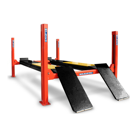
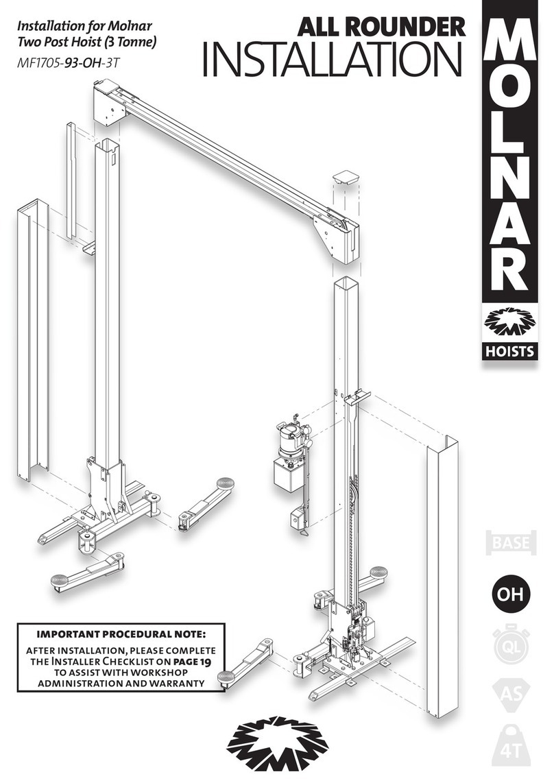
Molnar MF1705-93-OH-3T Guide

ALL ROUNDER
SERVICING
Maintenance for the Molnar
Two Post Hoist (3 Tonne)
MF1705-93-OH-3T
OH
OL
4T
AS
BASE

Molnar Hoists All Rounder Servicing
2
As the policy of Molnar Hoists is one of continuous improvement, the manufacturer reserves the right to change specifications
without notice. Information is correct and true at time of printing (July 2012)
Safety Operation Test 05
Wire Rope Failure Test 06
Check Carriage Rollers 07
Wear Pads 08
Lift Arms, Pivot Pins & Pick-Up Pads 09
Wire Rope Check 10
Pulleys Lubrication 12
Hydraulic System (Oil & Filter Replacement) 13
Electrical, Controls & Travel Limits 14
Structural & General Check 15
Replace Pulley Bush 15
Wire Rope & Pulley Removal 16
Wire Rope & Pulley Re-Insertion 18
Hydraulic Cylinder Replacement 22
Seal Replacement Procedure 23
Contents
Key
General warning
Electrical hazard
Servicing tip
Terminology
From time-to-time product or process descriptions can
change or evolve, for the purposes of clarity:
cables = wire ropes
pulleys = sheaves
shafts = pulley pins
safety = lock
lift pads = pick-up pads
release lever = lowering handle
Contents
This is owner manual 3 of 4

Molnar Hoists All Rounder Servicing 3Maintenance
Maintenance
6
10
12
1
.
5
24
1
D
Daily
óVisual Access & clearance
Inspection Work area clean & tidy
Structure
Loose or damaged parts
Decals & control markings
Hydraulic fluid levels
Pick up pads
óFunctional Operating controls
Inspection Safety mechanism
Unusual noise or vibration
Hydraulic system leaks
ó Check Accessories
Owner maintained - described in this Operation Manual
Service Professional - described in this Manual
Annually
If the 12 monthly service and safety
inspection is not performed, the
warranty is null and void.
óSafety operation test
óWire rope safety test
óCheck carriage rollers
óLubricate pulleys
óWire Ropes
óLift arms, pivot pins, pick-up pads
óHydraulic oil and system
óElectrical, controls and travel
limits
óStructural & general check
óAccessory conditions
After 6 weeks
The first oil change should
occur within the first three
months of operation (to
remove any contaminants
flushed through the
system).
óchange the hydraulic oil
óreadjust long cable and
arm locks
It is the Hoist Owner’s responsibility and Duty of Care to maintain the hoist. This must be recorded and retained.
Monthly
óIsolation points
óFlooring
óAnchor bolts
óStructural
alignment
óStructural
integrity
óVisual
appearance
óDisplayed notices
óCompliant
clearance
óSafety mechanism
óPick up pads
óLimit switches
óWire ropes
ó Check accessories
óLubrication
óPulleys
Six Monthly
óOil leaks from cylinder
óOil leaks at pipe joints
óAnchor bolts
2 Yearly
To keep the hydraulic system
(pump, seals, valves) in
good working condition, oil
changes are required every
two years to ensure any
degraded or contaminated
oil is cleaned out of the
system.
óReplace hydraulic oil
óClean tank and filter
10 Yearly
After 10 years of service, remove
Wire Ropes and pulleys from hoist.
Clean and inspect to ascertain
serviceability, replace if required.
It is recommended that pulley
bushes be replaced at this time.
If the hoist is in a high working or
extreme environment the Wire
Ropes should also be replaced.
óReplace pulley bushes
óReplace wear pads
óReplace pick-up pads
óWire rope & pulley removal
and inspection
Service and safety inspection on the hoist must be performed by a competent person. This must be recorded and retained.

Molnar Hoists All Rounder Servicing
4
Pre Servicing
Personal protective equipment
óGloves
óEar & eye protection
óSteel capped boots
óSafety cones, warning signs and tape
Electrician
A licensed electrician must perform all
electrical work including power connection
and wiring.
Lubricant recommended
óGrease > Marine grade wheel bearing grease
eg. molybdenum grease
óDry lubricant > CRC dry glide
> Wurth HHS dry lube
óGeneral lubricant > CRC Tac-2
> Wurth HHS Lube
óWire Rope lube > Lanotec heavy duty liquid lanolin
> 85-90 gear oil
óHydraulic oil >5 litres AWH46
Pre Servicing - Equipment
Tools
ó2.4 metre platform-style step ladder
or an appropriate elevated work platform
óHiLift / Wallaby Jack
óSafety prop, approximately 1800mm long
ó1200mm spirit level
óPry bar - heavy and light duty
óOil funnel with an end to fit into a W bsp hole
óStandard tool kit
>2 screwdrivers
>Phillips Head screwdriver
>Spark plug socket - 5/8” or 16mm
>Allan Key, 6mm and 3mm
>Clamp wrench (AKA vice grip)
>Cutting pliers (AKA wire cutters)
>Rubber mallet
>Hammer
>Adjustable wrench
>Spanner (16mm, 10mm and 13/16th imp)
>Shifting spanner - 450mm
>Socket set
>Needlenose pliers
>External circlip pliers
>Box cutter
>Black Texta

Molnar Hoists All Rounder Servicing 5
Base Bolts
Anchor Bolts
Safety Operation Test
Manual Safety Operation Test
1 Raise hoist to waist height.
2 Switch LOCK lever to OFF position and ensure it remains
in position.
3 Lubricate linkages and safety mechanism with spray lube.
4 Lower hoist to ground to check that the safety LOCK lever
resets to the ON position.
If safety mechanism does not operate properly,
check linkages or mechanism for damage.
Before you Service a Hoist
Servicing a Hoist must be
performed and recorded by a
competent person. Ensure you
are authorised to service a hoist
and that you are familiar with all
aspects of the hoist.
Cordon off work area using safety
cones or other safety barricade.
Ensure area is clear of any
obstruction prior to servicing.
Ensure there
is no vehicle
on the hoist.
Remove post covers on
both posts and the
Wire Rope cover on
non-control post.
There is significant
difference between
a “Base Bolt” and an
“Anchor Bolt”. Please
familiarise yourself
with the respective
bolt location
before
adjusting
bolts.
safety mechanism
linkages

Molnar Hoists All Rounder Servicing
6
Wire Rope and Failure Test
Wire Rope Failure Test
Wire Rope Test (Automatic Safety Test)
1 Raise Hoist to approximately 600mm and ensure LOCK
lever is in OFF position.
2 Using a lifting device (such as a Wallaby Jack), raise the
non-control-post carriage another 200mm. Ensure the
toggles on the back of the non-control-post carriage
engage onto safety teeth.
If safety toggles do not engage, toggles may need to
be lubricated or springs may need to be replaced
3 Check the manual safety has automatically reset to the
ON position on the control post carriage.
4 Remove Jack
5 Raise the hoist and reset the safety to the OFF position
and ‘jack’ the control carriage to test the manual safety
resets automatically to the ON position and remove jack.

Molnar Hoists All Rounder Servicing 7Check Carriage rollers
Check Carriage Rollers
1 Raise hoist to a comfortable working height.
2 Pry the carriage away from post (to remove the load off
the rollers) and wedge in position.
2b For the outside rollers wedge from the top of the carriage
(as illustrated above). For the inside rollers, wedge from
beneath the carriage (as illustrated below).
l
ocation of outside roller
location of inside roller
3 With the load off the rollers (load is now held by wedge)
check that the rollers rotate freely
4 Remove side bolt and slide out roller pin, roller and
spacers.
Note the orientation of the roller,
as it must be refitted in the same orientation.
5 Remove spacers and clean bush and pin. Inspect bush
and replace if necessary (ensure minimal non-rotational/
sideways movement between pin and bush) .
The roller must be at least 60mm in diameter with no flat
spots on the surface; otherwise replace.
6 Re-lubricate the inside of the bush (with grease). Use
grease to adhere the spacers to the sides of the roller.
Reinsert roller into carriage and insert the pin. Fasten the
side bolt.
7 Use a pry bar to remove wedge.
8 Perform for all load rollers on both carriages.
side bolt roller pin carriage carriagespacer spacerrollerbush
CAD

Molnar Hoists All Rounder Servicing
8
Wear Pads
Wear Pads
Wear pad inspection
1 Raise hoist to a comfortable working height.
2 Check free play in carriages by rocking the carriages
sideways. There should be 1-2mm of movement.
If there is excessive movement, replace Wear Pads.
DO NOT try to shim or adjust as this may cause the
carriage to jam.
1-2mm
Wear pad replacement
1 Remove the two M10 bolts securing the cover bracket on
the side of the carriage.
2 Using needle-nose pliers, remove the old pads and
replace with new, ensuring the flat face is positioned
towards the post (with the crosses are facing outwards).
3 Refit the cover bracket and re-secure with bolts.

Molnar Hoists All Rounder Servicing 9Lift Arms, Pivot Pins & Load Pads
Lift arms, Pivot Pins & Pick-Up Pads
Check swivel arms
1 Arm Extension: pull arms out to ensure that Extension
stops are in place.
If arms pull out, arms must be replaced.
2 Pads
>Check the pads screw up and down
freely.
>Check the thread is not worn, and
there is not excessive rocking
>Check the retention washer and
circlip is in place at the bottom of the
pad shaft, so that the pads can-not
screw out.
>Ensure that the rubber of the pad is
still pliable and soft.
3 Auto Arm Lock
>Check there is not excessive vertical movement at the
Arm Lock.
>Check the circlip on the pivot pin is in place.
>Check the split pin is still in place in the pivot pin.
washer
circlip
Replace Pick-up Pads
1 Using circlip pliers, remove the circlip from the
base of the pad. Remove the retaining washer
and unscrew pick-up pad. Discard.
2 Remove circlip and retaining washer from new pad and
screw into the lift arm. Replace washer and circlip.
3 Ensure that pad is secured and rotates freely.
>Raise the Lift Rod and disengage lock mechanism
to check smooth movement of arms.
>With extension arms fully extended, check
engagement and disengagement through
complete movement of arms.
>Raise the Lift Rod, rotate the arm with lift rod
unencumbered to check the lock engages.
>Visually inspect the locking teeth are in good
condition and hold when side pressure is
applied.
>Lower hoist to the ground
and test the Auto
Release.
>lubricate Lift Rod shaft
with dry- lubricant
If there is an issue with any of the listed checks,
disassemble the Arm Lock and reinstall, checking
and replacing worn parts (as per installation
instructions)

Molnar Hoists All Rounder Servicing
10
Wire Ropes
Wire Rope Check
Condition of twin wire ropes
1 Remove the weight from the twin wire ropes:
raise hoist until the safety toggles start to click.
Lower the hoist onto locks (by pulling the LOWERING
handle) continue to pull the LOWERING handle and
simultaneously pull out the twin Wire Ropes to compress
the cylinder (and create slack in the Wire Ropes).
2 Wipe the twin wire ropes clean (with a cloth).
3 Visually inspect for wear, rust and broken wires along the
entire length of Wire Rope. Bend the Wire Rope to check
for frays. Ropes are to be replaced according to the criteria
listed below.
4 Lubricate the Wire Rope with approved lubricant.
long wire rope
twin wire ropes
Wire rope must be replaced if:
a At any point the visible number of broken wires exceeds
7 wires in 78mm length of rope or 14 wires in 390mm
length of rope.
b The number of broken wires is likely to exceed the above
measure by the next service.
b A strand of wire is broken.
c A rope has been physically damaged by crushing or
deforming.
d If there are any inconsistent areas. If inconsistency is
found, it should be replaced or referred to a wire-rope
specialist for inspection.

Molnar Hoists All Rounder Servicing 11
Wire Rope Check
Condition of Long Wire Rope
5 Remove the weight from the long wire rope: raise Hoist
to approximately 200mm and switch LOCK lever to OFF
position. Using a lifting device, raise the non-control-post
carriage another 200mm, the toggles on the back of the
carriage must engage onto safety teeth. Leave the lifting
device in place, as a prop.
6 Repeat steps 2, 3 & 4 on the Wire Rope on the non-control-
post and across the top brace.
7 Raise the hoist and remove the prop.
8 Check the wire rope under the control unit: raise hoist
to maximum height and place safety prop under the
non-control-post carriage and lower hoist back onto prop
until the auto safety resets to the ON position.
9 Repeat steps 2, 3 & 4 on the Wire Rope on the control-post,
between the carriage and the bottom pulley.
10 Raise hoist and remove prop. Lower hoist to ground.
adjust
20mm
hold
Adjust Long Wire Rope
11 Check and adjust long Wire Rope pre-stretch: the non-
control-post carriage should be 20mm off the ground.
Adjust long wire rope as per installation instructions.
Wire ropes

Molnar Hoists All Rounder Servicing
12
Pulley Lubrication
Pulley Lubrication
1 Raise hoist until the safety toggles just start to click.
Lower the hoist onto locks (by pulling the LOWERING
handle) continue to pull the LOWERING handle and
simultaneously pull out the twin Wire Ropes to compress
the cylinder (and create slack in the Wire Ropes).
2 Control-post pulley: check pulley rotates freely and there
is not excessive free play in bush.
Push pulley to one side and lubricate the pin (spray
lubricant with extension nozzle), push pulley to the
opposite side and spray lubricate the other side. Rotate to
work lube into bush.
control-post pulley
control-post bottom pulley
top pulley
top pulley
3 Two top pulleys: check each pulley rotates freely and
there is not excessive free play in bush.
Push pulley to either side and lubricate the pin (spray
lubricant with extension nozzle) and rotate to work lube
into bush.
Ensure all bolts are tight.
4 Control-post bottom pulley: create more slack in the wire
ropes: use a lifting device to raise non-control-post up a
further 200mm, and lower onto safety locks.
Check each pulley rotates freely and there is not excessive
free play in bush.
Push bottom pulley to one side and lubricate the pin
(with spray lubricant with extension nozzle), push pulley
to the opposite side and spray lubricate the other side.
Rotate to work lube into bush.
Ensure all bolts are tight
If pulleys are not rotating freely, remove and inspect
pulley, pin and bush, replace as required
• replace Pulley Bush (see page 15);
• control-post pulley removal as per
Wire Rope & Pulley Removal (see page 16, steps 1 to 7);
• removal of top pulleys and control-post bottom
pulley (see Hoist Installation Manual).
spray lube

Molnar Hoists All Rounder Servicing 13
6 On a stable surface, remove the four screws securing the
oil tank top plate (with a 1/4” socket).
7 Lift off the tank lid (ensuring you do not
tear the gasket seal) including the filter.
Allow the oil to drain back into the tank
before flipping upside-down and placing
to one side (on a cloth).
8 Empty and clean the oil tank.
9 Slide the filter from the control valve
exhaust tube.
Drain and clean the filter with degreaser.
Blow it out and dry.
Inspect filter and replace if required.
Refit it to the control valve.
Clean the underside of the lid.
10 Refill the oil tank with 5 litres
of recommended hydraulic oil.
11 Refit the tank lid to the oil tank (reverse steps 7 & 6).
12 Refit the tank to the motor (reverse steps 5 to 1).
Hydraulic Oil & System
Basic check
1 Check for oil leaks around all unions and hydraulic
cylinder.
2 Check level and condition of the oil in the reservoir.
3 Top up as required: unscrew the breather cap and use a
funnel to pour Hydraulic oil to the level indicated.
Oil must be replaced at first service;
then at least every 2 years.
To Remove the oil tank & Replace the oil
1 Fully lower hoist to the ground.
2 Turn off power to the hoist.
3 Remove the LOWERING handle by removing the split pin
from the Lowering Handle and sliding out of the bracket
near the control button.
4 Disconnect the oil pipe fitting at the top of the tank.
Clean any oil that might leak.
5 Loosen the four bolts securing the tank to the motor.
6 Supporting the tank with one hand, release the bolts and
remove the tank from the motor.
lowering handle
release lever
oil pipe fitting
tank bolts
Hydraulic System

Molnar Hoists All Rounder Servicing
14
Electrical, controls & travel limits
1 Check the operation of limit switches: raise hoist to
ensure that limit switches stop the hoist operating
beyond the limits of travel.
2 Visually inspect electrical components for damage.
>Overhead limit switch sensor bar: ensure it is
mounted securely to its mounting point, and moves
freely. Lubricate slide pins.
>Electrical conduit: ensure it is not worn,
cracked or disconnected at either end.
>Side limit switch: ensure it is mounted securely to its
mounting point, and moves freely.
>Junction boxes: check both boxes are mounted
securely.
>Control button box: check the box is mounted securely
to its mounting bracket. Check that the cover is fitted
securely and that the button moves freely.
3 Check LOWERING handle pivot is operating freely. Ensure
it does not hold the valve open. Lubricate with spray
lubricant.
4 Ensure the LOWERING handle is not bent and is secured
with split pin (at the pivot).
overhead
limit switch
sensor bar
overhead limit switch
side limit switch
conduit
junction
junction
lowering
handle
pivot
control button box
conduit

Molnar Hoists All Rounder Servicing 15
Structural & General Check Replace Pulley Bush
1 Use a spirit level to check posts are vertical (in both
directions).
2 Check shimming under post has not moved and is not
rusted.
3 Inspect anchor bolts for rust and check tension.
4 Check the cylinder spigot pin is located in its mounting
hole (in the bottom of the cylinder).
1 Place pulley over an open brace (such as two planks or
open vice) and use a and use a 31 mm diameter steel or
brass drift pin to drive out the old bush.
2 Replace with a new bush. Gently hammer new bush into
pulley (with steel or brass drift pin), ensuring it is flush on
both sides of the pulley.
3 Grease the sides and affix spacers (grease holds spacers
in place while inserting pulley assembly into hoist).
4 Re-grease inside the bush.
pulley bush
5 Visually inspect hoist for any signs of damage,
rust or bent components.
6 Clean posts of old lubricant and re-lubricate rear tracks
with spray lubricant. Apply dry lubricant to inner roller
track and side wear pad tracks on both posts.
Apply grease to outer roller tracks.
See Operation Manual for more information
8 Refit covers to posts.
9 Check operating instructions are correctly positioned
and clearly legible.
10 Complete Service/Inspection Report and owners Log
Book.
incorrect correct
Structural & General Check & Replace Pulley Bush

Molnar Hoists All Rounder Servicing
16
Remove Twin Wire Ropes
1 Raise hoist until the
safety toggles start to
click.
Lower the hoist onto
locks (by pulling the
LOWERING handle).
Isolate power supply
then continue to pull
the LOWERING handle
and simultaneously
pull out the twin Wire
Ropes to fully compress
the hydraulic cylinder
(and create slack in
the Wire Ropes). Note:
Cylinder must be fully
compressed to access
inside brackets.
Use a lifting device
(such as a Wallaby Jack)
to raise the non-control-
post carriage a further
200mm, and lower onto
safety locks.
2 Use external circlip
pliers to remove the
trigger bracket circlip
and let hang. Place
retaining washer and
circlip to one side.
3 Remove the 2 M6 bolts holding the cable bracket in
position and slide the bracket from the ends of the twin
cables.
Twin Wire Ropes can be slid down
and removed from carriage.
4 Use a pry bar to lever the double pulley
out of the cylinder
5 Raise the double pulley up the inside of
the control-post and out through the
wider opening at the top.
6 From the pulley, remove the two bolts
that securing the cable retaining
bracket and remove. The pulley is now
free of the Wire Ropes - place to one side.
Wire Rope & Pulley removal
Wire Rope & Pulley Removal
7 Inside the control-post, above hydraulic cylinder, is a
bracket. Remove one bolt and swing the bracket away.
Pull Wire Ropes down over this bracket and remove
second bolt to remove.
8 remove the M6 bolt holding the
cylinder locating ring in position and
remove ring.
9 On the control-post carriage, remove
the short linkage spring between the
safety mechanism and the axel.
Compress the long cable spring and
remove the axel. Remove the spring and
the collar.
Slide the Wire Rope out of the carriage.
10 Remove the bottom pulley. Remove the cable retaining
bracket by removing the two side screws. Remove the
pulley by removing the two securing bolts that hold the
pulley assembly to the post.
Lift pulley out from post and place to one side.
11 The twin Wire Ropes can
now be pulled from the
bottom of the control-post:
loosen the Wire Rope ends
(which appear as solid
silver cylinders) from their
cable retaining plate while
simultaneously
pushing Wire
Ropes down
into the
control-post.
Wire Rope ends must be fed through the
locators in the post.
pulley
cylinder
twin
wire
ropes
twin cable bracket
trigger bracket circlip
short linkage spring
bottom pulley
cable retaining bracket
cable retaining bracket screws
pulley assembly bolts

Molnar Hoists All Rounder Servicing 17 Wire Rope & Pulley removal
Wire Rope & Pulley removal
Remove Long Wire Rope
1 From the non-control-post
carriage at the end of the long
Wire Rope, use a hammer and
pin punch to drive the roll-pin
out of the thread of the long
Wire Rope.
Remove the nut from the end of
the Wire Rope.
Pull the Wire Rope out of the
bracket, placing the sleeve and
spring to one side.
2 Remove the top pulley assembly from out of the top of
the non-control-post. Rotate it upside-down and place
it on top of the hoist (for easy access). Remove the M6
bolt securing the pin at the side of the pulley housing
and remove pin. Remove the pulley and remove the Wire
Rope. Replace the pin in the pulley, and place pulley and
housing to one side (away from hoist)
3 Remove the pulley from the top of the control-post.
Remove the M6 bolt securing the pin at the side of the
posy cap. Support the pulley as you remove the pulley
pin. Feed the pulley out through the bottom of the post
cap, ensuring both pulley spacers remain with the pulley.
Place pulley to one side.
4 On the control-post
carriage, remove the
short linkage spring
between the safety
mechanism and the axel.
Compress the long cable
spring and remove the
axel. Remove the spring
and the collar.
Slide the Wire Rope out of the carriage.
axle
long cable spring
collar
wire rope
Always discard removed/used split pins and roll pins
and use new ones during reassembling
5 Remove the bottom pulley. Remove the cable retaining
bracket by removing the two side screws. Remove the
pulley by removing the two securing bolts that hold the
pulley assembly to the post.
Lift pulley out from post and place to one side.
6 Pull the long Wire Rope on the non-control-post. Feed
the Wire Rope into the locator spot at the bottom of the
control-post.
Continue pulling the Wire Rope through the non-control-
post, until Wire Rope is completely removed.
Always guide the long cable during removal to
prevent accidents or injury!
bracket
spring
roll pin
cable nut
sleeve
short spring

Molnar Hoists All Rounder Servicing
18
Unpack and place new Wire Ropes
on clean surface to protect integrity
When reinserting new twin Wire Ropes, clearly mark
which Wire Rope is LEFT and which is RIGHT with a
texta, to ensure Wire Ropes are not twisted when fed
behind the hydraulics.
1 Insert the LEFT Wire Rope into the LEFT hole (in the cable
retaining plate, inside the control-post)
Push the Wire Rope up the post.
Keep a slight twist to the left-hand side (to ensure it
remains to the left-hand-side of the post).
2 Pull the Wire Rope completely through the opening in
the control-post and hang to left-hand-side of the control
post.
L
Wire Rope & Pulley Re-Insertion
3 Repeat the process for
the right-hand Wire Rope
(twisting Wire Rope to the
right to avoid twists).
4 Check Wire Ropes have not
crossed over.
5 Ensure both Wire Ropes
are positioned between
cable retaining bracket
lugs.
Secure Wire Ropes with
cable retaining bracket:
finger tighten screw one
side (with M6 screw),
swing into place and
finger tighten screw on
the other side.
Ensure the bottom Wire
Rope-ends are seated
“hard up” in the cable
retaining plate (inside the
bottom of the post) before
tightening cable retaining
bracket.
6 Insert the long Wire Rope; feed the non-threaded end of
the long Wire Rope into the top of the control-post, down
the inside of the post.
Feed the other
end of the Wire
Rope over the top
of the hoist and
down the outside
of the non-control-
post. Ensure the
Wire Rope passes
through the post
cover mounting
bracket.
L
R
cable
retaining
bracket lugs
hard up
in cable
retaining
plate

Molnar Hoists All Rounder Servicing 19
Line up pulley fork spigot
with the hole in the end
of the piston rod and pull
down on the twin wire
ropes until the fork is fully
seated.
10 Attach double Wire Ropes to carriage:
assemble Wire Rope ends.
Note: Retrieve assembly from old Wire Ropes (springs
and nuts etc) and attach to new Wire Rope.
Slide on spring-washer, then spring. Compress the spring
and place a washer and fix with cable nut. Wind nut on,
until the screw is just proud.
Place both Wire Ropes onto carriage bracket slot and
secure with bracket.
Note: the bracket mounts needs to be inserted between
the spring-washer and the Wire Rope.
Affix bracket with 2 x 12mm M6 bolts.
Wire Rope & Pulley Re-Insertion
7 At the bottom of the
control-post, pull the
end of the long Wire
Rope down through the
cut-out in the right-
hand side of the cable
retaining plate.
Completely pull it out
and sit the end into the
back of the carriage.
8 Reinstall cylinder
support ring:
insert into the cut-out
sidewards, feed it over
the top of the hydraulic
cylinder (ensuring
the connector plate is
pointing downwards)
and secure with 12mm
M6 bolt.
9 Reinstall double pulley:
holding pulley in line
with insert point; place
Wire Ropes on pulley
(ensuring correct and
parallel alignment)
and fit cable retaining
bracket on double pulley
(with 10mm M6 side
bolts).
Lift pulley into larger
cut-out in side of post,
ensuring Wire Ropes
sit into their grooves in
the double pulley, when
lowered inside the post.
Lower down onto
cylinder, ensuring Wire
Ropes remain tight into
their grooves.
cablespring washerspringwashernut

Molnar Hoists All Rounder Servicing
20
carriage mount
spring
collar
axle mount
11 Refit spring and safety axle at end of the long Wire Rope:
with the end of the long Wire Rope in the carriage mount,
place the spring and collar over it. Align the hole (in the
end of the Wire Rope) with the axle mount. Push safety
axle through. Reattached the linkage.
12 Install bottom pulley
Re-grease all pulley
bushes before refitting
>Reinsert the pulley assembly into
the post, ensuring the side brackets
locate into the mounting blocks
inside the post.
>Fit 2 x M6 bolts through each side
of the bracket and secure pulley
to the mounting post. Do not over
tighten.
>Reaching inside the post above the
twin pulley, pull excess long Wire
Rope to secure the Wire Rope into
the bottom pulley groove.
>Recheck the Wire Rope is located
in the pulley correctly and refit the
cable retaining bracket to secure
the Wire Rope within the pulley.
Then retighten side bolts ensuring
the bracket sits firmly against the
stop.
>Check the pulley rotates freely.
13 Insert control-post top pulley
>From the top of the control-post,
locate the top pulley and remove.
Using a small amount of grease for
hold, position the pulley spacers on
each side of the pulley. Re-grease
the pulley bush.
>Reinsert the top pulley into the smaller of the two
openings underneath the control-post cap, being
careful not to dislodge the spacers on either side.
>Align pulley and pin holes before fitting the pulley pin
and bolting to secure.
>Ensure the Wire Rope is laying correctly in the pulley
groove.
14 Insert non-control-post top pulley
>At the top of the non-control-
post, place top pulley. Unscrew
the bolt and remove the pulley
pin to remove the pulley and
spacers.
>Feed the Wire Rope through
the pulley assembly. Re-grease
the pulley bush and re-grease
spacers to re-attach.
>Slide the pulley back down until
the pulley lines up with the pin
hole, ensuring the spacers do
not dislodge before refitting the
pulley pin and securing the bolt.
Check the pulley spins freely.
>Flip and insert the pulley
assembly into the top of the
post, with the bracket hook
pointing outwards.
Wire Rope & Pulley Re-Insertion
Other manuals for MF1705-93-OH-3T
1
Table of contents
Other Molnar Lifting System manuals
Popular Lifting System manuals by other brands

AMGO
AMGO BP-9X Installation and service manual

WPG
WPG MRTALPCH611LDC Test Procedure

twin busch
twin busch TW 242 E Installation, operation and maintenance manual

Ricon
Ricon BR2SS Series Troubleshooting

Invacare
Invacare 9700 Installation and operating instructions

Pressalit Care
Pressalit Care R2170 Mounting instruction