Nektar Pacer User manual

www.nektartech.com
www.nektartech.com
User Guide

2 Nektar Pacer User Guide www.nektartech.com
Content
Introduction 4
Box Content 4
Pacer Features 4
Minimum System Requirements 4
Getting Started 5
Connection and Power 5
Nektar DAW Integration Files for Pacer 5
Pacer Functional Overview 6-7
Presets 8
Loading a Preset Using the Arrow Footswitches (C&D) 8
Loading a Preset Using the [Preset] Footswitch (A) 8
Using the Encoder to Load a Preset 8
Loading a Specific Preset Using Any Assignable Footswitch 8
Factory Preset List 9
Control Edit 10
Selecting a Control for Programming 10
Setup 10
Steps 10
Type 11
Type Data Settings 11
Setting MIDI Channel for a Step 12
LED Color 12
Relays - Connecting and Programming 13
External Step Select 13
MMC and Preset 13
Save 14
Store 14
MIDI Configuration (sending MIDI data when a preset is recalled) 14
Global 15
Global Channel 15
Encoder Assign 15
Panic 16
MIDI OUt Jack Source 16
Footswitch Behavior 16
Expression Pedal 17
Relay Behavior 17
Patch Up/Down Function 17
E-Ctr, Dump and Boot 18
Using the Encoder as a MIDI Control 18
Backup Presets 18
Factory Restore 19

www.nektartech.com Nektar Pacer User Guide 3
Dispose of product securely, avoiding exposure to food sources and ground water. Only use the product in accordance with the instructions.
Note: This equipment has been tested and found to comply with the limits for a Class B digital device, pursuant to part 15 of the FCC Rules. These limits are
designed to provide reasonable protection against harmful interference in a residential installation. This equipment generates, uses and can radiate radio
frequency energy and, if not installed and used in accordance with the instructions, may cause harmful interference to radio communications. However, there
is no guarantee that interference will not occur in a particular installation. If this equipment does cause harmful interference to radio or television reception,
which can be determined by turning the equipment off and on, the user is encouraged to try to correct the interference by one or more of the following mea-
sures:
• Reorient or relocate the receiving antenna.
• Increase the separation between the equipment and receiver.
• Connect the equipment into an outlet on a circuit different from that to which the receiver is connected.
• Consult the dealer or an experienced radio/TV technician for help.
CALIFORNIA PROP65 WARNING: This product contains chemicals known to the State of California to cause cancer and birth defects or other reproductive
harm.
For more information: www.nektartech.com/prop65
Pacer firmware, software and documentation is the property of Nektar Technology, Inc and subject to a License Agreement.
© 2018 Nektar Technology, Inc. All specifications subject to change without notice. Nektar is a trademark of Nektar Technology, Inc.
Pacer

4 Nektar Pacer User Guide www.nektartech.com
Thank you for buying the Nektar Pacer MIDI DAW footswitch controller.
Originally Pacer was intended to be a DAW controller giving musician’s hands free control of their computer music environment. Enthusiasm
got the better of us so we soon added a bunch of additional MIDI control functionality that enables control of MIDI preamps and effects
whether in hardware or virtual plugin form. Add to that 4 relays which can switch any switch socket devices such as amp channels or reverb
switching. With 10 programmable footswitches and up to 4 additional external footswitches (optional, not included) Pacer offers a lot of
switching power. Whether you are recording or playing live, Pacer boosts creativity through hands free control.
Box Content
Your Pacer box contains the following items:
• The Pacer footswitch controller
• Printed Guide
• A standard USB cable
• Unit is powered via USB so any additional power supply is optional and not included
Pacer Features
• 10 programmable footswitch controls with RGB LEDs • RGB LEDs for each footswitch
• 1 Preset footswitch for recalling presets and navigation • 24 user configurable presets
• 2 expression pedal sockets for connecting expression pedals • 2 read only presets for DAW track and transport control
• 2 TRS jack connectors for connecting up to 4 external footswit-
ches
• Up to 16 MIDI messages or relay switches can be activated
instantly when a preset is recalled
• 2 TRS jack connectors for connecting up to 4 switch sockets such
as reverb, tremolo or channel switching on an amp
• Up to 6 steps programmable for each control within a preset,
each sending a MIDI messages or executing an action
• MIDI output can be used as a USB MIDI interface, for direct MIDI
connection or both at the same time.
• Steps can be sent in one shot when a switch control is
pressed, or in a sequence of presses.
• 1 encoder with push switch for programming, navigation and
control
• Option to setup steps as sub presets, expanding preset use
beyond convential use
• 2 row LED display • MIDI LED feedback for MIDI CC messages
• USB for connecting to a computer, USB host or USB power
supply (for power only)
• Nektar DAW integration for Transport and Track control com-
plete with dedicated presets and icons
• DC 9v 600mA center negative power supply socket (PSU not
included)
Minimum System Requirements
Pacer: USB class compliant (no driver needed) works with Windows XP, Vista, 7, 8, 10 or higher. Mac OS X 10.5 or higher, Linux (Ubuntu)
Nektar DAW Integration: Windows Vista, 7, 8, 10 or higher. Mac OS X 10.7 or higher. Check Nektar DAW Integration documentation or
marketing information for support of legacy DAW versions.
Introduction

www.nektartech.com Nektar Pacer User Guide 5
Connection and Power
Pacer is USB class compliant. That means there is no driver to install - it just needs to be plugged in.
Pacer uses the built-in USB MIDI driver class driver which is already part of your operating system on Windows and OS X.
The first steps are simple:
• Locate the included USB cable and plug one end into your computer and the other into the Pacer’s USB socket on the rear panel.
• If you want to connect additional foot switches plug them into the 1/4” jack socket on the back of the keyboard labeled “FS“. Pacer will
automatically detect the polarity of the foot switch. You can connect up to 4 foot switches but will need additional Y-spliter or insert
cables to access all of them.
• Set the power switch on the back of the unit to On
Your computer will now spend a few moments identifying the Pacer and subsequently you will be able to set it up for your DAW.
Nektar DAW Integration Files for Pacer
If your DAW is supported by Nektar DAW integration software , you’ll need to first create a user account on our website and subsequently
register your product to gain access to the downloadable files applicable to your product.
Start by creating a Nektar user account here: www.nektartech.com/registration
Next follow the instructions given to register your product and finally click on the “My Downloads” tab to access your files.
IMPORTANT: Make sure to read the installation instructions in the PDF guide, included in the downloaded package, to ensure you don’t
miss an important step.
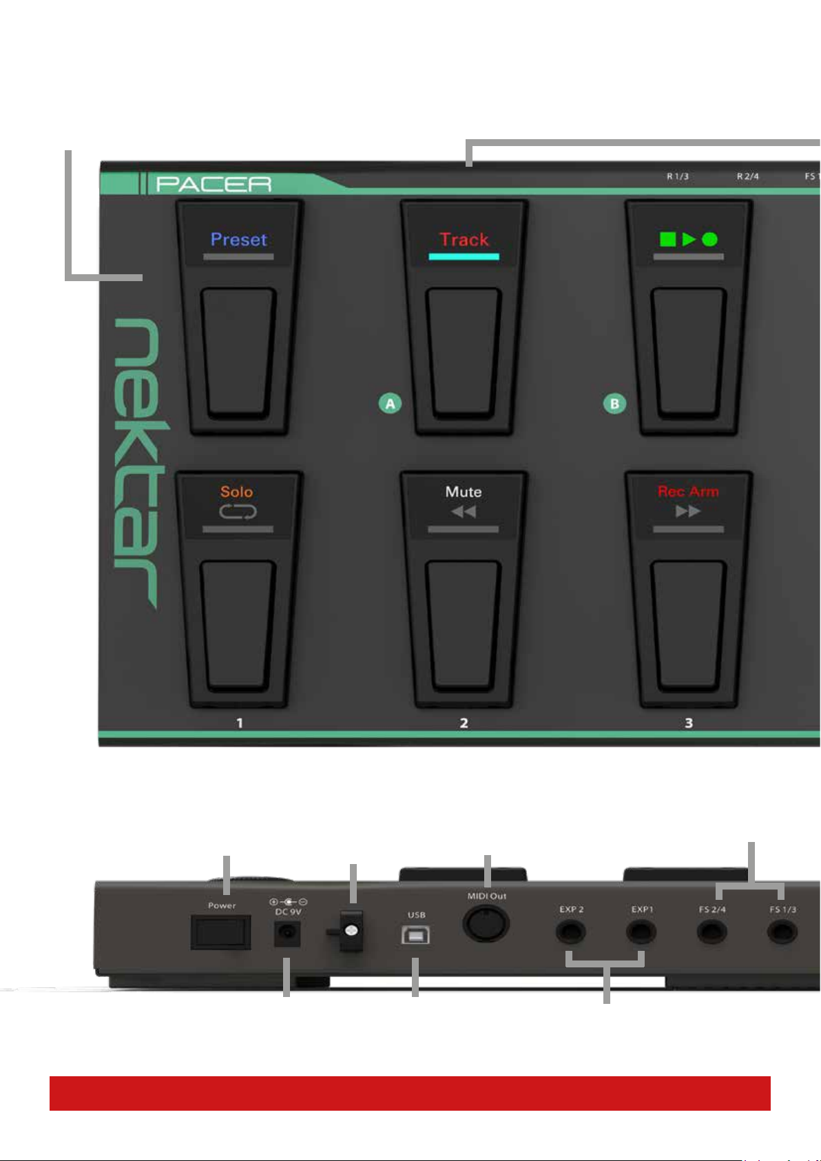
6 Nektar Pacer User Guide www.nektartech.com
MIDI Output Jack
Connect external MIDI equipment.
Can be used as USB MIDI interface as
well as for direct control - or both.
Cable Tie
Tie your USB or PSU cable.
Unscrew with screwdriver and
tighten again for secure t.
Expression Pedal sockets 1 & 2
Standard expression pedals can be con-
nected for additional real-time control.
USB Connector
Connect to USB host/computer.
Unit powered via USB.
Footswitch sockets 2/4 and 1/3
2 TRS 1/4” jack sockets allow connection
of up to 4 external footswitch pedals.
Pacer Functional Overview
Power Supply
Power supply socket (PSU
optional) 9v 600mA, center
negative, 2.1mm barrel con-
nector.
Power On/O
Preset Switch
Press and hold for 2 seconds, then select a preset using the switches,
by rst selecting bank A/B/C/D followed by preset number 1-6.
[Preset] is also the back button when navigating Pacer menus.
Switches A-D
In factory presets, assignments for these 4 swiches are A: Track preset (for DAW control), B: Transport preset (for DAW control), C: Load previous
preset, D: Load next preset. Each of the switches can be congured to send any other function or MIDI message.

www.nektartech.com Nektar Pacer User Guide 7
Footswitch sockets 2/4 and 1/3
2 TRS 1/4” jack sockets allow connection
of up to 4 external footswitch pedals.
Kensington Lock
Relay sockets 2/4 and 1/3
1/4” TRS jacks require Y-splitter/insert
cables to connect all 4 relays. 1/4” TS
jacks can be used to connect 2 relays.
Data Encoder/Push Select
Turn Data Encoder to scroll through menus
and options.
Press the encoder cap to select.
Switches 1-6
Assignable switches can be programmed to send MIDI messages, control one
of the 4 relays or load presets. When DAW Transport or Track functions are
assigned, the top and middle row icons are illuminated.
Switches A-D
In factory presets, assignments for these 4 swiches are A: Track preset (for DAW control), B: Transport preset (for DAW control), C: Load previous
preset, D: Load next preset. Each of the switches can be congured to send any other function or MIDI message.

8 Nektar Pacer User Guide www.nektartech.com
Pacer has a total of 24 user presets available in 4 banks A-D with 6 presets each. A preset contains configuration of the 10 foot switches
(A-D and 1-6), 4 external foot switches and 2 expression pedal sockets. For each switch in a preset you can send up to 6 messages either
when the switch is pressed or in a sequence of switch presses. In addition, it’s possible to send out up to 16 messages when a preset
is recalled which means a rig can be configured at load time with switches immediately available for performance changes. With these
advanced features, Pacer provides recall and control options that go way beyond conventional footswitch controller products. The best
part is that you don’t need to create duplicate presets to make simple changes as you perform.
Loading a Preset Using the Arrow Footswitches (C & D)
If you have just switched Pacer on, the default user preset selected is A1. From here, you can press arrow up switch to load the next preset
(A2) or press the arrow down switch to load the previous preset (D6).
Note: Each of the 4 switches A-D can be user configured to send any other function/message as part of a preset.
Loading a Preset Using the [Preset] Footswitch (A)
You can select any of the 24 user presets at any time by doing the following:
• Press and hold the [Preset] switch until the LEDs for switches 1-6 blink.
• Select the desired bank by pressing one of switches A-D.
• Select the desired preset within the bank by pressing one of the switches 1-6.
• If the correct bank is already selected, simply press switches 1-6 to select a preset.
The [Preset] button is not user assignable so presets can be loaded at any time using this method.
Using the Encoder to Load a Preset
From the top menu where the display reads “Pacer”, do the following:
• Move the encoder to select the preset menu. The display now reads “Prset”
• Press the [Encoder] to select the menu. You should hear an audioable click and the [Preset] switch LED blinks.
• Turn the encoder to scroll through the user presets.
• Press the [Encoder] to load the currently selected preset.
Loading a Specific Preset Using Any Assignable Footswitch
Footswitches A-D, 1-6 and external footswitches 1-4 can each be programmed to load a specific preset. within a preset. Sounds confusing?
Ok here is how it works.
When preset is being configured in Control Edit, one assignment type option for footswitch controls is “Preset’. With that type selected, a
target such as preset A4 can be selected. After making that assignment, pressing the corresponding footswitch, will load preset A4.
However that setting is not retained unless you save it as part of the current preset. In other words, pressing the footswitch that loads
preset A4 after the assignment is made, will immediately overwrite it with it’s own assignments. So this function requires a bit of planning.
Example: Throughout a gig, presets A6, B2, C4 and D1 are needed. If I have a spare footswitch available in every preset, such as D, it can be
used it to toggle through the 4 presets needed. That would leave the other 9 switches free for performance programming. In this case, D
in preset A6 would be programmed to load preset B2, preset B2 would program D to load preset C4, preset C4 would program D to load
preset D1 and finally preset D1 would program D to load preset A6.
Presets
www.nektartech.com Nektar Pacer User Guide 9
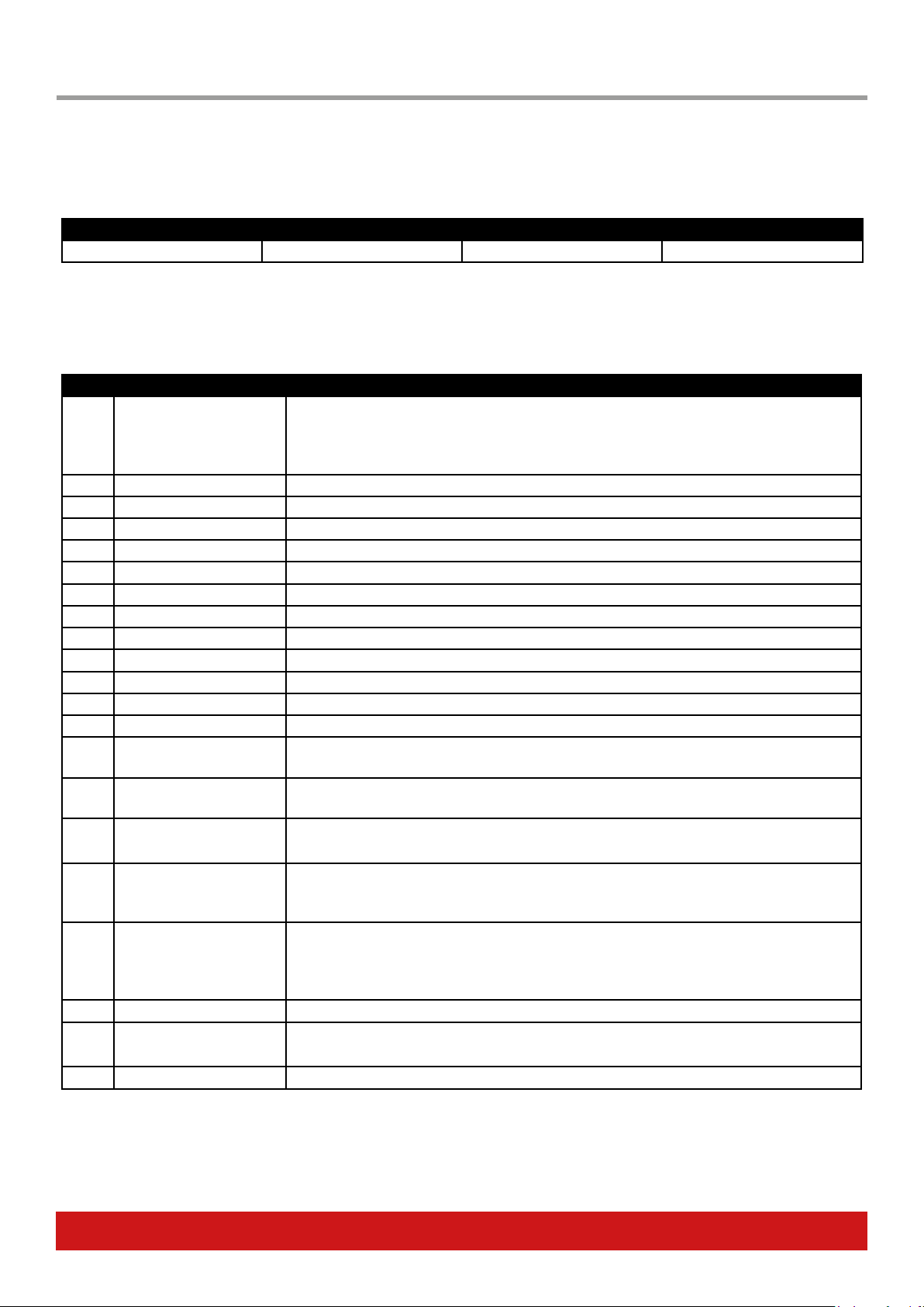
Factory preset
Pacer’s 24 factory presets have been designed with common functionality for assigned for switches A-D as per the below chart.
A B C D
Load DAW Track Preset Load DAW Transport Preset Load Previous Preset Load Next Preset
The Transport and Track presets are only used with Nektar DAW Integration and are read only. If you don’t plan to use a DAW with Pacer,
switch A & D can be assigned to send out MIDI messages or another function. The following chart details how each Pacer factory preset is
configured.
Preset Preset Name Description
A1-A4 Program change 0-5 Each preset assigns MIDI program change messages to switches 1-6 in the range 0-23. The LED
switch for the last sent message is fully illuminated with other switches dimmed. You can use
these presets to change programs on any MIDI compatible equipment. They are also ideal for
changing program patches on virtual systems such as NI GuitarRig.
A5 MIDI Notes Send out MIDI notes E/F#/G/A/B/C, FS1=-1 octave, FS2=-2 octaves, FS3=+1 octave, FS4=+2 octaves.
A6 Relay 1-4 A simple setup so you can try out the 4 relays, assigned to switches 1-4.
B1 Line6 Helix 1 Assigned to control Helix pedals 1-5: snapshot, set list, tuner and tap tempo.
B2 Line6 Helix 2 Assigned to control Helix pedals 6-10, snapshot, set list, tuner and tap tempo.
B3 Line6 Pod HD Controls Pod HD pedals 1-8, tuner and tap tempo.
B4 Line6 Pod 2.0/XT Turn individual effects on and off on Pod XT.
B5 Fractal Audio AxeFX 1 Assigned to switch individual page 1 effects on and off, tuner and tap tempo.
B6 Fractal Audio AxeFX 2 Assigned to switch individual page 2 effects on and off, tuner and tap tempo.
C1 Avid Eleven Rack Turn individual Avid Eleven Rack effects on and off, tuner and tap tempo.
C2 Kemper Profiler Turn individual Kemper Profiler effects on and off, tuner and tap tempo.
C3 Line6 PodHD/Helix Looper Control Pod HD and Helix Looper functions
C4 Fractal Audio AxeFX Looper Control Axe FX Looper functions
C5 Elektron Octatrack Pickup
Machine
Navigate Octatrack Pickup Machine tracks and control Looper functions.
C6 Electro Harmonix 45000
Looper
Navigate Harmonix 45000 tracks and control Looper functions.
D1 LED color demonstration Switches 1-6 are all assigned MIDI CCs and each Stomp Switch has a unique color.
D2 Keyboard tool box Switches 1-6 and the expression pedals inputs are configured to transmit common keyboard
performance messages. Switch 1 transmits CC64 for sustain, Expression Pedal 1 transmits CC7
for volume and Expression Pedal 2 transmits CC11 for expression.
D3 GM CCs Switches 1-6 are configured to transmit CCs which are associated with specific effects, according
to the General MIDI Spec. Only GM compatible devices will respond to these messages by default.
Otherwise, this preset can be used to control software and hardware which have MIDI learn
functions.
D4 MIDI Machine Control Control Play, Stop, Record, Forward and Rewind on MMC compatible DAWs.
D5 Step Sequence
demonstration
Switches are configured in Sequence mode with 4 active steps. FS1-4 select the active step.
D6 Init patches No assignments.
Factory Preset List
10 Nektar Pacer User Guide www.nektartech.com
The Control Edit menu is where control assignments for any of the 10 footswitches, 4 external footswitches and 2 expression pedal sockets
are programmed.
Selecting a Control for Programming
• From the top default menu, move the Data Encoder until you see “CTRL“ in the display. This is the Control Edit menu.
• Press the [Data Encoder] to select the menu. The LED of the [Preset] button will now blink
• Press or move one of the controls. The control is now selected for programming.
• If the selected control is either switch 1-6 or switch A-D, the corresponding LED will blink.
• While in the top level of the Control Edit menu, press or move one of the controls to change selection at any time.
Next move the [Data Encoder] to scroll through the menu options in the Control Edit menu.
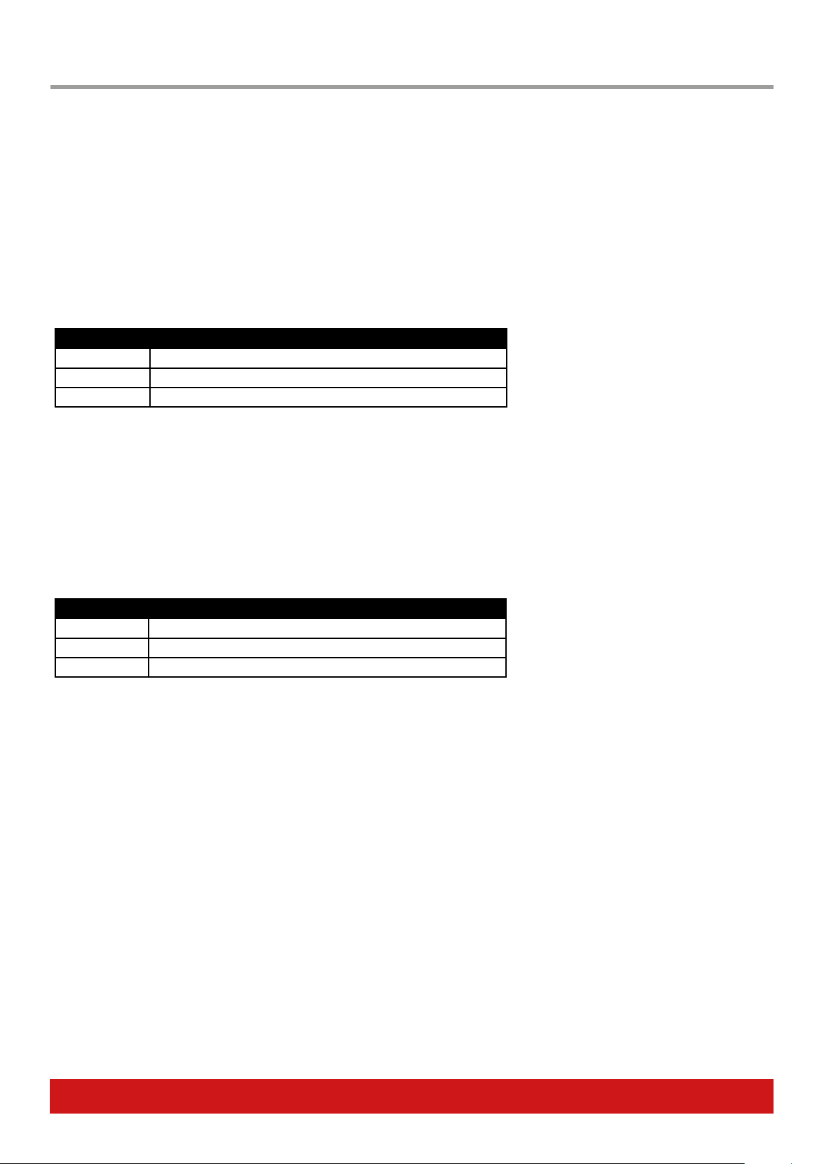
Setup
When you move the [Data Encoder] the first option is SETUP. For each control you can program up to 6 messages or actions in 6 steps. The
Setup menu defines how the assigned messages should behave.
• With “SETUP“ displayed, press the [Data Encoder] to select the menu.
• Select one of the 3 options in the chart below.
• Press the [Data Encoder] to select and exit to the top menu level.
Note that ALL is default so you don’t need to enter the menu to select this setting.
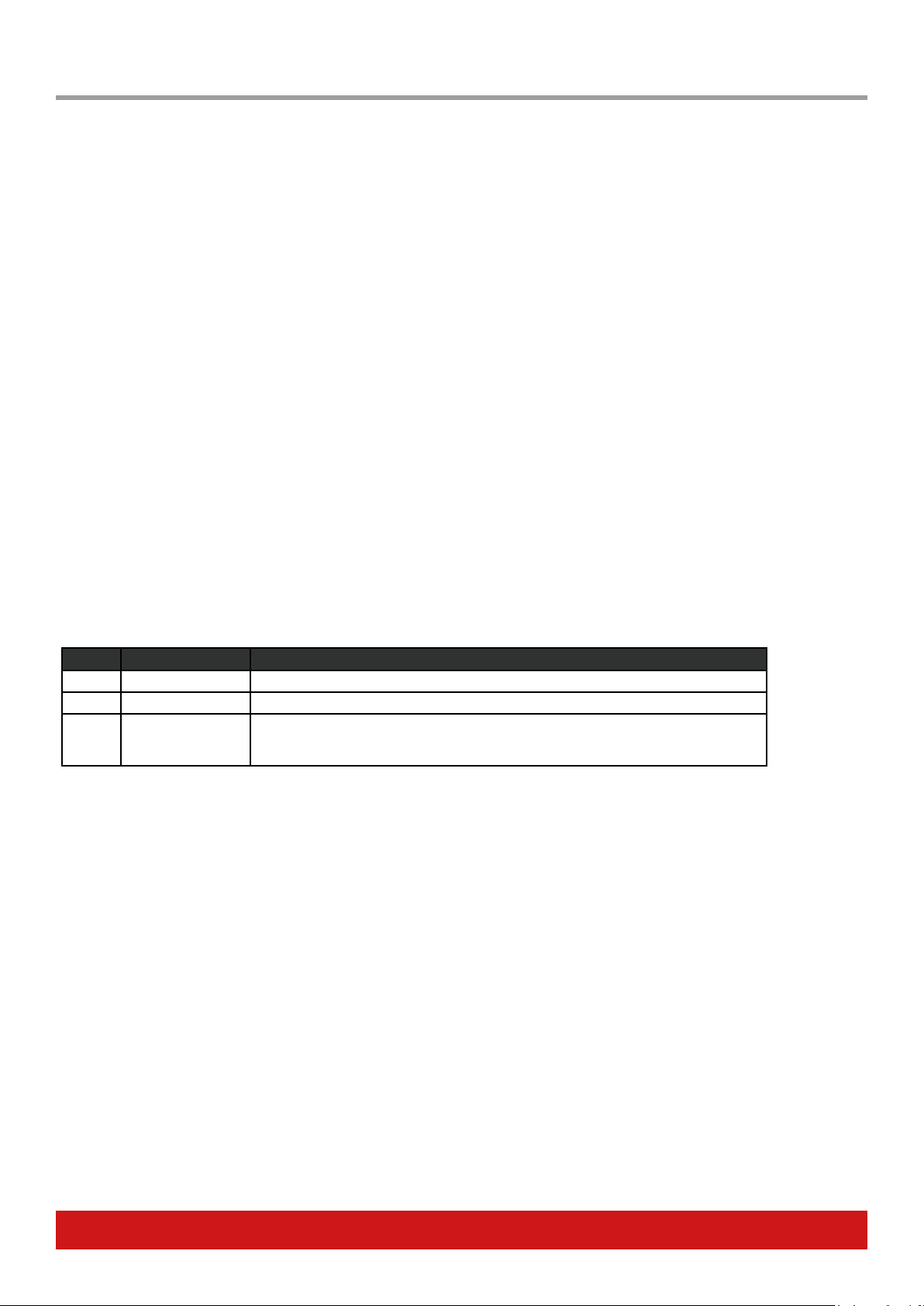
Control Function Description
ALL All steps, one shot Execute all active steps when the control is pressed/moved. This is the default setting.
SEq Sequence Execute one active step at a time, advancing in a sequence with each press.
ESS External Step Select Select this option if you want the steps for this control to be selected by another
control. For example, you may want one of the expression pedals to change step (and
therefore the MIDI message it sends) when you press a foot switch.
Steps
Move the [Data Encoder] again and select „STEPS“. Pacer‘s switches 1-6 now represet the 6 steps that can be programmed to the selected
control.
• Press switch 2 to 6 to activate or deactivate steps.
• Activated steps illuminate white. All other switches illuminate blue.
• Step 1 cannot be deactivated because each control at minimum needs one step for assignment.
• If a switch control‘s LED is blinking, it‘s the selected control (i.e. the control you are currently activating and deactivating steps for)
Once the steps needed have been activated, move on to program messages or functions for each of them.
Control Edit

www.nektartech.com Nektar Pacer User Guide 11
Type
Move the [Data Encoder] until you see „TYPE“ in the display. Type is the menu where you specify what kind of message or action the select-
ed step will send or execute.
• Press [Data Encoder] to select the menu. The type setting for the currently selected step is displayed in the display (for example CC
TOG or PGBNK etc).
• The selected step is illuminated red. Press any other switch illuminated white to select a different step.
• Move the [Data Encoder] to select the type you need for the current step (see chart below).
• Press [Data Encoder] when you are done. The display now reads „TYPE“ which means you are back at the top menu level.
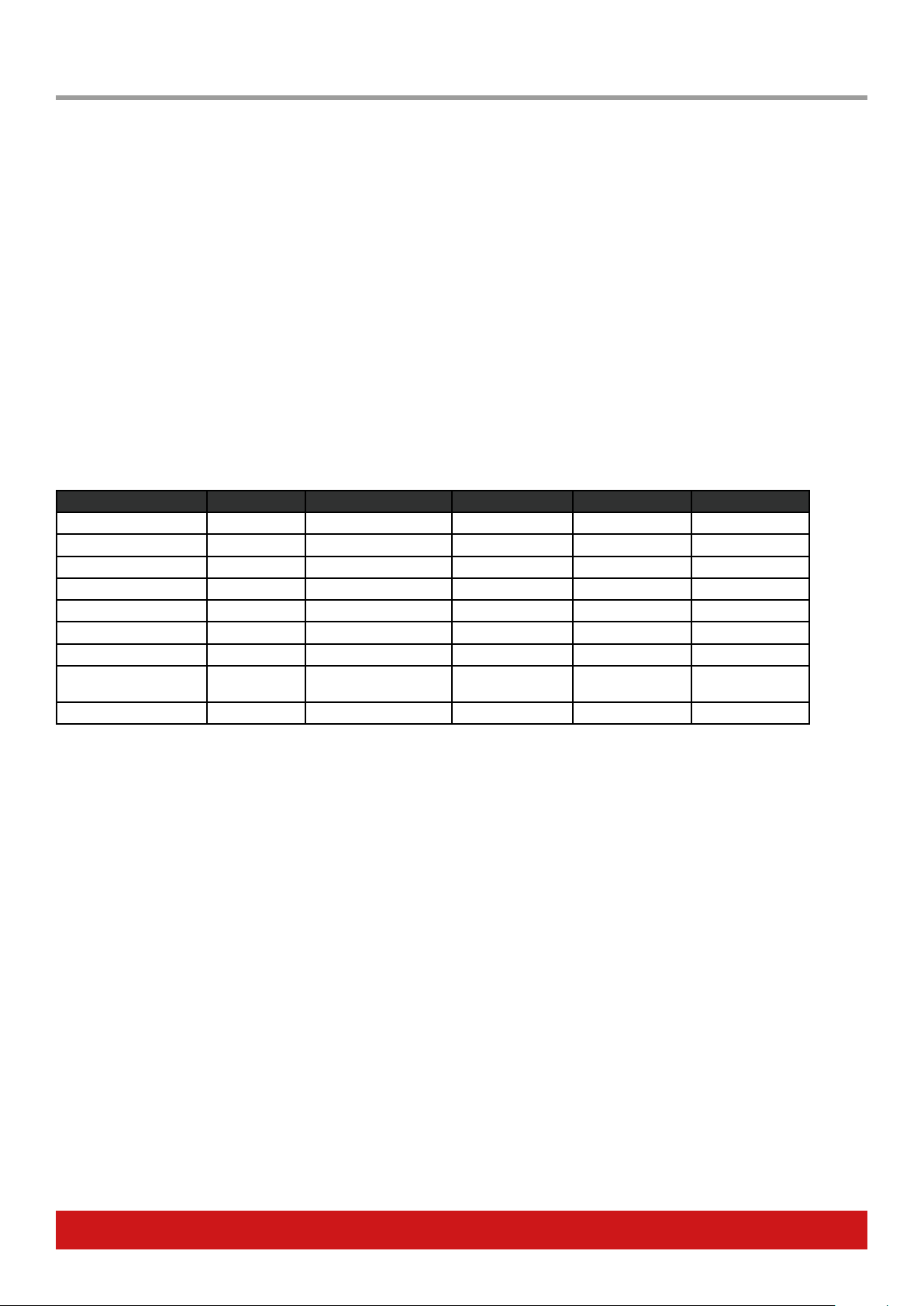
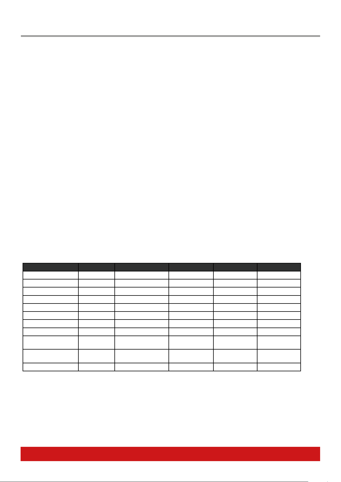
Type Data Settings
The type selelected for the current step determines what options are available. The chart below shows the types available as well as the
setting options for each in column‘s Data 1-3 as well as MIDI Channel if applicable.
Type Display Abb. Data 1 Data 2 Data 3 MIDI Channel
MIDI CC Toggle CCTOG MIDI CC (0-127) Press 1 (0-127) Press 2 (0-127) 0=Global, 1-16
MIDI CC Trigger CCTRG MIDI CC (0-127) Down (0-127) Up (0-127) 0=Global, 1-16
MIDI CC Step CCSTP MIDI CC (0-127) Start (0-127) End (0-127) 0=Global, 1-16
MIDI Note NT Note (0-127) Velocity (0-127) n/a 0=Global, 1-16
MIDI Note Toggle NTTOG Note (0-127) Velocity (0-127) n/a 0=Global, 1-16
MIDI Program & Bank PGBNK Program (0-127) Bank LSB (0-127) Bank MSB (0-127) 0=Global, 1-16
MIDI Program Step PGSTP Start (0-127) End (0-127) n/a 0=Global, 1-16
MIDI NRPN Coarse NRPNC Value (0-127) LSB (0-127) MSB (0-127) 0=Global, 1-16
MIDI NRPN Fine NRPNF Value (0-127) LSB (0-127) MSB (0-127) 0=Global, 1-16
MIDI Machine Control MMC Device ID (0-127) Command (0-127) n/a n/a
Pacer Relay Outputs RELAY Mode (nO/nC/Lt)* Select (1-4) n/a n/a
Pacer Preset PRSET Target (A1-D6, Trc, Trn) n/a n/a n/a
Pacer Preset Inc/Dec PR-+ Direction (Inc/Dec) n/a n/a n/a
Control Step Select STEP Target (A-D, 1-6, FS1-4,
EXP 1-2)
Step (1-6) n/a n/a
Control Step Inc/Dec STP-+ Target (A-D, 1-6, FS1-4,
EXP 1-2)
Direction (Inc/Dec) n/a n/a
Nektar DAW Control DAW Function (Solo, mute
etc)
n/a n/a n/a
O OFF n/a n/a n/a n/a
Example:
• With type set to MIDI CC Trigger (CCTRG) for the current step, move the [Data Encoder].
• When the display reads “CC“, press the [Data Encoder].
• Move the [Data Encoder] to select the MIDI CC number from 0-127, you want the step to send.
• Press [Data Encoder] and move it to “DWN”.
• Press [Data Encoder] and set the Down value by moving the [Data Encoder]. This is the value sent when the control is pressed.
• Press [Data Encoder] and move it to “UP”.
• Press the [Data Encoder] and set the Up value by moving the [Data Encoder. This is the value sent when the control is released.
• Press the [Data Encoder] to accept this last change.

12 Nektar Pacer User Guide www.nektartech.com
Setting MIDI Channel for a Step
MIDI messages, can be sent on any MIDI channel from 1 to 16 or on the global MIDI channel (value=0).
• Move the [Data Encoder] until ”M CHA“ appears in the display.
• Press the [Data Encoder].
• Move the [Data Encoder] to select a value from 1-16 or 0 (Global MIDI Channel)
• Press the [Data Encoder] to accept the change.
LED Color
A selection of LED colors are available for each of the 10 switches (A-D and 1-6). How they are used and what they mean is completely
user configurable though by default each color represent an assignment type (see chart below). A color can be programmed for both on
and off or instead of choosing different colors you can use the same color for both on/off with the off setting dimmed (A=full illumination,
b=dimmed).
Here is how the setting is programmed in the Control Edit menu:
• Move the [Data Encoder] until ”LED“ appears in the display and press the [Data Encoder] to select it.
• Move the [Data Encoder] to scroll through the menus in the chart below and press the [Data Encoder] to select.
• Set the Value using the [Data Encoder] and press the [Data Encoder] to set it.
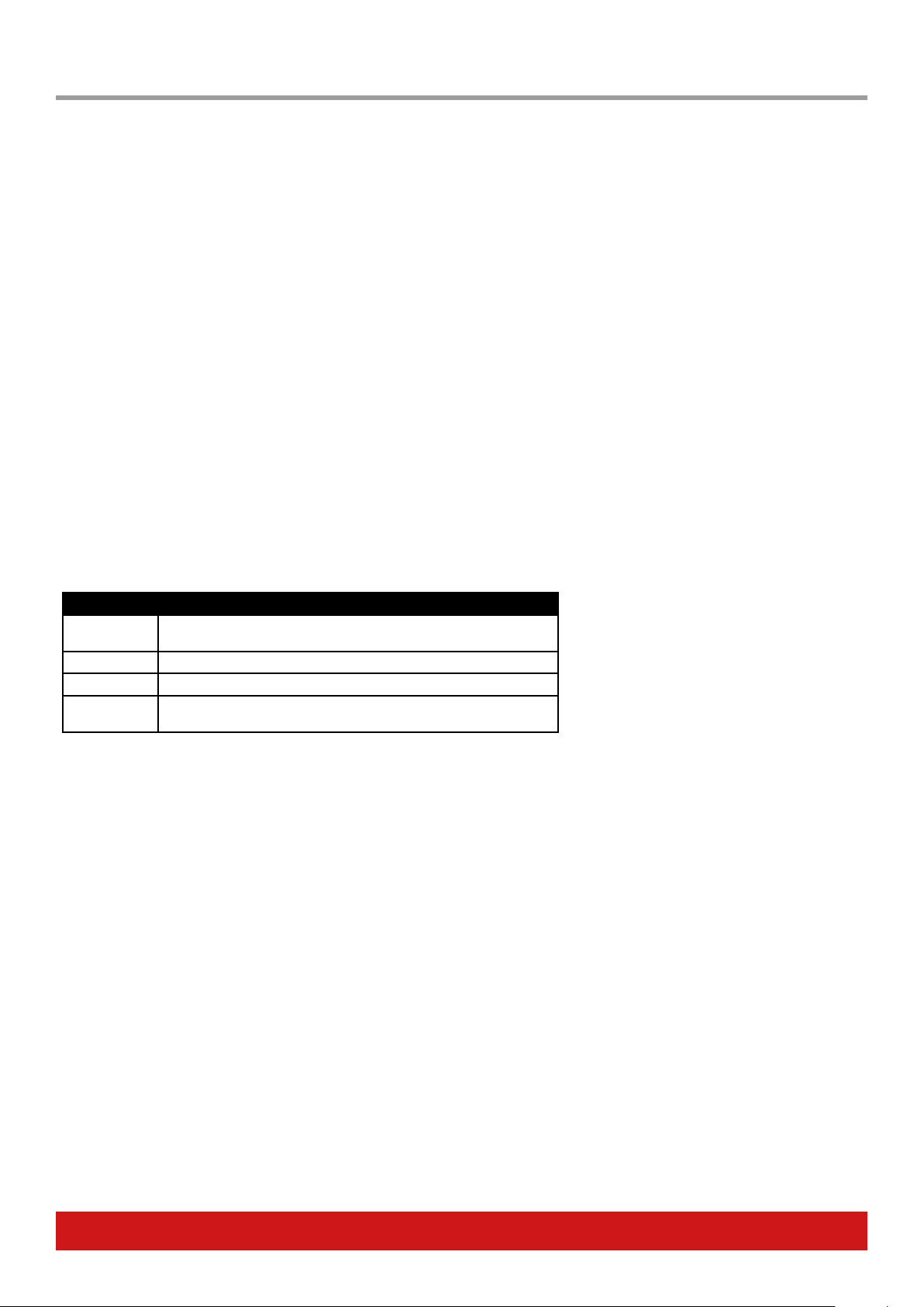
Chart 1
Menu Display Value Function
MIDI MIDI O/On If On, LED on and o colors are triggered by the assigned MIDI
message received via the USB MIDI port.
On Color ONCLR O, 01a/b to 12 a/b, Default Sets the color used for On/maximum value state
O Color OFCLR O, 01a/b to 12 a/b, Default Sets the color used for O/minimum value state
LED Number LEDNM 0-3 Sets which of up to 3 LED’s should be illuminated on the switch.
0=default, 1=bottom, 2=middle, 3=top.
Back BACK n/a Return to Control Edit top level
Chart 2
Color No Color Default Color for Message Type
1A / 1b Step select
2A / 2b Preset select
3A / 3b MIDI Program
4A / 4b
5A / 5b MMC
6A / 6b
7A / 7b MIDI Note
8A / 8b DAW function
9A / 9b MIDI cc
10A / 10b Relay
11A / 11b NRPN Coarse, NRPN Fine
12A / 12b
A=full illumination, b=dimmed

www.nektartech.com Nektar Pacer User Guide 13
Relays - Connecting and Programming
The 4 relays can be used to switch amp settings such as channel, reverb, tremolo or in fact any other function that requires a standard foot
switch including act as a sustain pedal for a keyboard.
Pacer has 2 TRS 1/4“ jack sockets which each connect to two relays. To get use of both relays on one socket you will need to connect a
Y-splitter cable with one TRS 1/4“ jack at one end split to two TS 1/4“ jacks at the other end. The cable is commonly known as an insert
cable and should be easy to find.
You can also connect a standard TS 1/4“ cable in which case only one of the relays will be working.
To program a switch to control a relay works the same way as any other message type so check the previous pages for more details if
needed.
• In the TYPE menu, select RELAY and press the [Data Encoder].
• Next select “MODE” and press the [Data Encoder].
• Move the [Data Encoder] to scroll through the 3 options: Normally Closed (nC], Normally Open (nO) and Latching (Lt)*.
• Press the [Data Encoder] to revert to the top level menu.
• Move the [Data Encoder] to “SELECT”.
• Press the [Data Encoder] and move it to chose one of the relays 1-4.
* Normally Closed and Normally Open functions like footswitch pedals that are either open or closed when the pedal is pressed and then
revert to their default state upon release. The two options determines the polarity. If you want a behavior that alternates the open/closed
state with each press, chose latching.
External Step Select - How Does it Work?
Being able to configure one switch to change the current step in a step sequence of another control, is a very powerful way of expanding
the use of a preset. Here are a few use cases:
Use one switch such as D to toggle through step assignments for switches 1-6. For example,
To set this up you would set all controls other than D, to ESS in Setup and create the amount of steps with the programing you would
need. D would be programmed to message type “STP-+” so it can toggle through
A similar approach would be to use the 4 A-D buttons to switch between steps 1-4.
MMC - Transport Control for DAWs Without Nektar DAW Integration
If your DAW is not supported by Nektar DAW Integration, you can use MMC (MIDI Machine Control) to control basic transport functions
from Pacer
First enable MMC in your DAW, then select preset D4. It’s already set up for MMC control using switches 1-6.
14 Nektar Pacer User Guide www.nektartech.com
In the Save menu, the current settings for controls A-D, 1-6, FS1-4 and EXP1-2 can be stored to presets A1-D6. In addition, the “MIDI Con-
figuration” menu enables up to 16 MIDI messages or relay settings to be stored with each preset and sent immediately, when the preset is
recalled. That means that your entire rig can be configured immediately as you load a preset for a new set or song.
Store
• From the top level menu, move the [Data Encoder] until “Save” appear in the display.
• Press the [Data Encoder] and “Store” appears in the display.
• Press the [Data Encoder] again and move it to select the preset location you want to save to (A1-D6). To exit press [Preset].
• Press the [Data Encoder] to store the current setting to the selected location.
MIDI Configuration
In the MIDI configuration menu, up to 16 messages can be programmed for triggering when a preset is recalled. Note that you do need to
store the preset after you have created the settings you need, so they are stored with the preset that you want to trigger them.
The following options are available:
Type Display Abb. Data 1 Data 2 Data 3 MIDI Channel
MIDI CC CC MIDI CC (0-127) Value (0-127) n/a 0=Global, 1-16
MIDI Note NT Note (0-127) Velocity (0-127) n/a 0=Global, 1-16
MIDI Program & Bank PGBNK Program (0-127) Bank LSB (0-127) Bank MSB (0-127) 0=Global, 1-16
MIDI NRPN Coarse NRPNC Value (0-127) LSB (0-127) MSB (0-127) 0=Global, 1-16
MIDI NRPN Fine NRPNF Value (0-127) LSB (0-127) MSB (0-127) 0=Global, 1-16
MIDI Machine Control MMC Device ID (0-127) Command (0-127) n/a n/a
Pacer Relay Outputs RELAY Mode (nO/nC/Lt)* Select (1-4) n/a n/a
Nektar DAW Control DAW Function (Solo, mute
etc)
n/a n/a n/a
O OFF n/a n/a n/a n/a
This menu works very similar to the Control Edit menu and these are the steps you need to go through to set it up:
• From the top level menu, move the [Data Encoder] until “Save” appear in the display.
• Press the [Data Encoder] and “Store” appears in the display.
• Move the [Data Encoder] and select “M CFG”
• Press the [Data Encoder] to select the menu.
• The display now shows “1” in the display. This represents the first message of 16 that you can program. Move the [Data Encoder] to
select a different message number but if this is the first message you will be assigning, simply press the [Data Encoder] to select.
• “Type” now appears in the display. Press the [Data Encoder] to select and then move the [Data Encoder] following to select one of the
options in the chart above.
• Press [Data Encoder] when you have found the message type you want.
• Use the [Data Encoder] to select and set the Data options and MIDI Channel as per the chart above.
• To program the next message, press the [Preset] switch and select the next message number.
• When all messages have been configured press [Preset] until you see “Store” in the display. You will need to save the preset or all
settings will be lost when you recall a different preset.
• To exit the Save menu completely at any time, press [Preset] until you see “PACER” in the display.
Save
www.nektartech.com Nektar Pacer User Guide 15
The Global menu contains setting for the rear sockets and other functions that only needs to be changed occasionally.
• From the top level menu, move the [Data Encoder] until “GLBL” is displayed.
• Press the [Data Encoder] to select.
Turning the [Data Encoder] scrolls through the Global menu options as described following.
Global channel
This sets a general MIDI channel for the device. When a control is programmed in Control Edit to send on the global channel (value 0), this
menu setting defines which MIDI channel the message is ultimately transmitted on. If the global channel is changed, any controls in any
presets sending on the global MIDI channel, will now send on the channel.
• Move the [Data Encoder] until you see “G Ch”“ in the display.
• Press the [Data Encoder] to select the menu.
• Move the [Data Encoder] to select MIDI Channel 1-16.
• Press [Data Encoder] to set and revert to the Global menu.
Encoder Assign
The Encoder can be used to send MIDI messages, just in case you need an extra control to control output volume for example. Because
the programmed setting is not part of a preset, the encoder‘s assignment is set in the Encoder Assign global menu.
• In the Global Menu, use the [Data Encoder] to selected “ENC”.
• Press the [Data Encoder] and when “Type” appears in the display, press it again.
• Use the [Data Encoder] to scroll through the message type options as per the chart below.
• Press [Data Encoder] when you have found the message type you want.
• Use the [Data Encoder] to select and set the Data options and MIDI Channel as per the chart above.
Type Display Abb. Data 1 Data 2 Data 3 MIDI Channel
MIDI CC CC MIDI CC (0-127) Value (0-127) n/a 0=Global, 1-16
MIDI CC Relative CCR Note (0-127) Velocity (0-127) n/a 0=Global, 1-16
MIDI NRPN Coarse NRPNC Value (0-127) LSB (0-127) MSB (0-127) 0=Global, 1-16
MIDI NRPN Fine NRPNF Value (0-127) LSB (0-127) MSB (0-127) 0=Global, 1-16
PitchBend PB Device ID (0-127) Command (0-127) n/a n/a
AfterTouch AFT Mode (nO/nC/Lt)* Select (1-4) n/a n/a
Program Select PRG Start (0-127) End (0-127) n/a 0=Global, 1-16
Preset Select PRSET Start (A1-D6) End (A1-D6) n/a n/a
Step Select STEP Target (A-D, 1-6, FS1-4,
EXP 1-2
Step (1-6) n/a n/a
Nektar DAW Control DAW Function (Solo, mute
etc)
n/a n/a n/a
O OFF n/a n/a n/a n/a
Once the assignment has been set for the encoder, go to the top level menu and scroll through the menus until “ENC” appear on the
display.
• Press the [Data Encoder] to lock it to the assigned function.
• Moving the [Data Encoder] will now send the message you assigned.
• Press the [Data Encoder] twice to exit.
Global

16 Nektar Pacer User Guide www.nektartech.com
Panic
It can happen that MIDI messages can get stuck with an on setting (it‘s mostly common with note messages) waiting for an off setting.
Panic is used to send a reset instruction to connected MIDI devices.
• Move the [Data Encoder] until you see “Panic”“ in the display.
• Press the [Data Encoder] to select the menu.
The reset is sent immediately and Pacer returns to the Global Menu.
MIDI Out Jack Source
The MIDI Out jack can be used to send MIDI messages directly from Pacer controls or indirectly when used as a USB MIDI interface.
• Move the [Data Encoder] until you see “M OUT”“ in the display.
• Press the [Data Encoder] to select the menu.
• Move the [Data Encoder] to select options Int/USB/I U*
• Press [Data Encoder] to set and revert to the Global menu.
*The option “I U” allows the MIDI jack to send MIDI messages directly from Pacers controls and work as a USB MIDI interface, at the same
time.
Footswitch Behavior
Connected momentary footswitches are by default detected automatically at power-up. However it may be that a footswitch is not detect-
ed correctly or that a latching foot switch is connected. Settings for each foot switch can be programmed manually.
• Move the [Data Encoder] until you see “FS“ in the display and press the [Data Encoder] to select the menu.
• Move the [Data Encoder] to select a footswitch 1-4, and then press the [Data Encoder] to select.
• The display now reads “MODE”. Move the [Data Encoder] to select one of the options listed in the below chart.
• Press [Data Encoder] to set and revert to the Global menu.
Mode Options Footswitch Type
Aut Momentary, auto detect (default)
nO Momentary, normally open
nC Momentary, normally closed
LAt Latching
www.nektartech.com Nektar Pacer User Guide 17
Expression Pedal
The default relay behavior can be set globally in this menu.
• Move the [Data Encoder] until you see “EXPDL“ in the display and press the [Data Encoder] to select the menu.
• Move the [Data Encoder] and choose either 1=Expression pedal 1 or 2=Expression pedal 2, and then press the [Data Encoder] to
select.
• The display now reads “MODE”. Move the [Data Encoder] to select on of the options listed in the below chart.
• Press [Data Encoder] to set and revert back to the menu where you can select either expression pedal 1 or 2.
• To return to the Global menu either press [Preset] or select “Back” using the [Data Encoder]
Mode Option Expression pedal type
1
2
3
Relay Behavior
The default relay behavior can be set globally in this menu.
• Move the [Data Encoder] until you see “RLY“ in the display and press the [Data Encoder] to select the menu.
• Press the external footswitch that you want to change setting for, and then press the [Data Encoder] to select.
• The display now reads “MODE”. Move the [Data Encoder] to select on of the options listed in the below chart.
• Press [Data Encoder] to set and revert to the Global menu
Mode Option Relay Behavior
1 Momentary, normally open
2 Momentary, normally closed
3 Latching
Patch Up/Down Function
The Track and Transport presets used for Nektar DAW Integration control use switches C and D to select previous or next patch in your
DAW. Some plugins however don’t respond to these messages and instead require you to send a MIDI program message. This global
menu allows you to select one or the other option.
• Move the [Data Encoder] until you see “PTCHF” in the display and press the [Data Encoder] to select the menu.
• Move the [Data Encoder] to select either “PRG” or “DAW”. PRG=MIDI Program Change. DAW=DAW Patch Change
• Press [Data Encoder] to set and revert to the Global menu
18 Nektar Pacer User Guide www.nektartech.com
Using the Encoder as a MIDI Control
The Data Encoder can be used as an extra MIDI Control. It‘s assignment is not stored as part of a preset so once setup you can use it for
one purpose, anytime. Here is how you activate it.
• Move the [Data Encoder] until you see “E_CTR” in the display and press the [Data Encoder] to select the menu.
• Move the [Data Encoder]. It’s now sending out the assigned MIDI message or function as setup in the Global Menu.
• Double press the [Data Encoder] to revert to the top level menu.
Backup Presets
Presets and settings can be backed up and restored at any time. Using this feature it’s therefore possible to not only recover data that
could otherwise have been lost but also create a mix of different presets from multiple files. An application capable of recording MIDI
susex data, such as a DAW, is required.
Here are the steps to create backupfiles.
• Move the [Data Encoder] until you see “Dump” in the display and press the [Data Encoder] to select the menu.
• Move the [Data Encoder] and select one of the options in the chart below.
• Launch your DAW and make sure it’s setup to record MIDI sysex data. Create a MIDI track and press record.
• Press the [Data Encoder] to send out the sysex data to your DAW. Once completed Pacer will revert to the top level menu.
Mode Description
ALL All preset settings, Global menu and current settings are sent via
sysex. This is a complete current settings backup
CUr Sends only the current settings.
GLb Sends only the Global menu settings.
A1-D6 Select a specic preset from A1-D6 and send only the data for that
preset.
To reload a backup file, just play it back the sysex data.
E_CTR, and Backup

www.nektartech.com Nektar Pacer User Guide 19
Factory Restore
Restoring to factory settings will revert all settings to the status they were at when you first purchased the unit. Make sure to backup any
presets or settings that you want to retain.
Here are the steps for restoring to factory settings
• Make sure your Pacer is switched off.
• Press the [Preset] switch and hold it while switching power on.
• The display reads “G CFG”. Move the [Data Encoder] until it reads “RESET”.
• Press the ‘Data Encoder”. The reset will activate immediately.
• Once complete, Pacer reverts to the top level menu.
Factory Restore

www.nektartech.com
Designed by Nektar Technology, Inc
Made in China
Other manuals for Pacer
1
Table of contents
Other Nektar Recording Equipment manuals

Nektar
Nektar Reason T4 User manual

Nektar
Nektar SE49 User manual

Nektar
Nektar Impact LX49+ Manual

Nektar
Nektar Panorama P1 User manual

Nektar
Nektar Impact LX Mini User manual

Nektar
Nektar Impact LX49+ User manual

Nektar
Nektar Aura User manual

Nektar
Nektar Impact iX49 User manual

Nektar
Nektar IMPACT GXP 49 User manual

Nektar
Nektar Aura Safety guide


Popular Recording Equipment manuals by other brands


StarTech.com
StarTech.com USB2HDCAPM quick start guide

Lennox
Lennox 22X18 Installation and setup guide

GVP
GVP A1200 SCSI/RAM+ user guide

Viessmann
Viessmann Vitocom 100 Installation and service instructions for contractors

ALLEN & HEATH
ALLEN & HEATH PL-12 Service information

Rolls
Rolls HE18 BUZZ OFF user manual


