7700 MultiFrame Manual
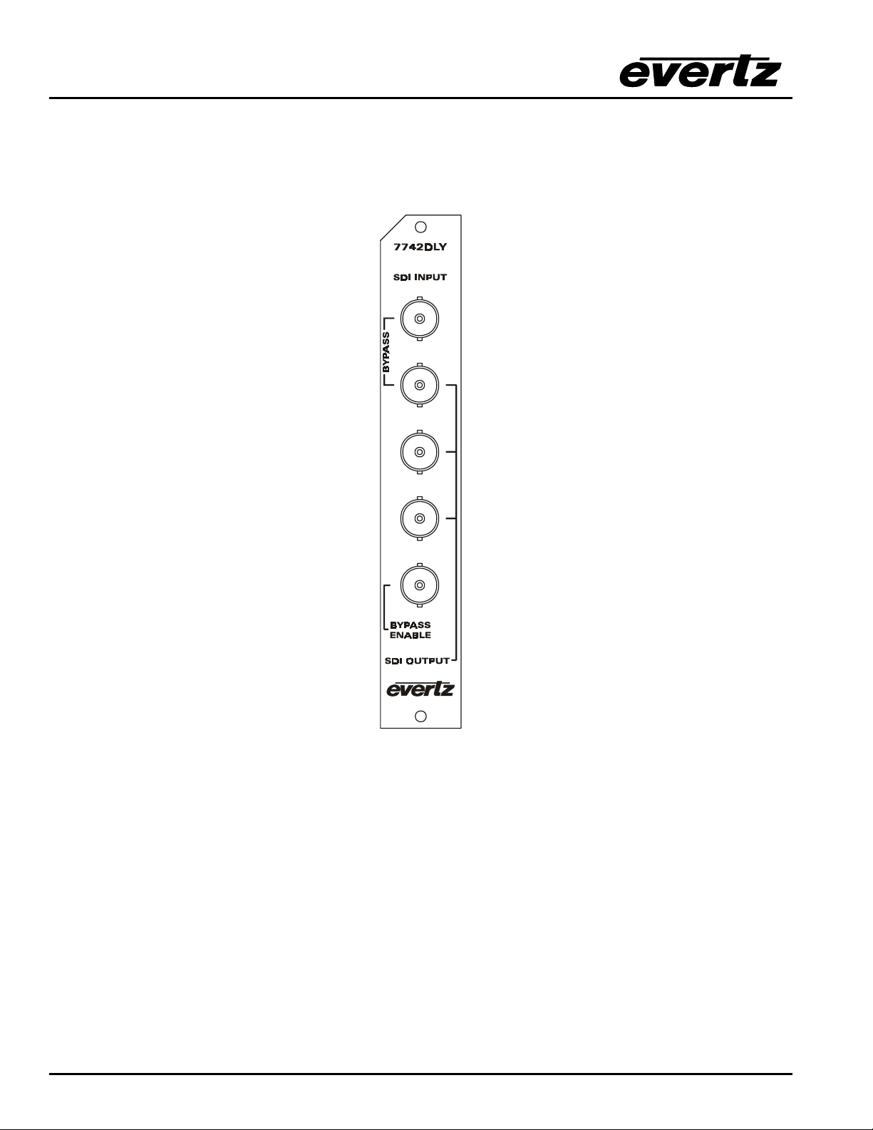
7740 Series SDI Video Delay
7740DLY-4 Revision 1.2
4. STATUS LEDS
MODULE OK This Green LED will be On when the module is operating properly
LOCAL FAULT This Red LED makes it easy to identify one module in a frame that is missing an
essential input or has another fault.
The LED will blink on and off if the microprocessor is not running.
The LED will be on solid when the cable length warning is active, when input video
is lost or there is a fault in the module power supply.
VIDEO PRESENT: This Green LED will be On when there is a valid video signal present at the module
input.
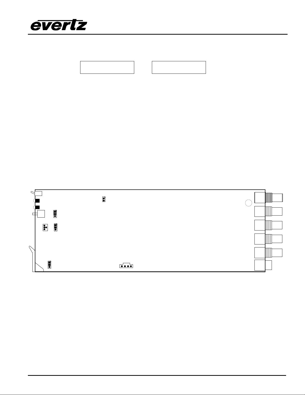
5. CONFIGURING THE 7740DLY USING THE ON SCREEN MENU
An On screen menu (OSD) is used to configure many of the test generator’s parameters. The three
position, return to center, toggle switch and momentary pushbutton located on the front edge of the
module are used to navigate the OSD setup menus and configure the cards various controls.
To enter the OSD menu system, press and hold the pushbutton and then press the toggle switch up for 5
seconds. This will bring you to the main setup menu where you can use the toggle switch to move up and
down the list of available sub menus. An arrow (>) moves up and down the left hand side of the menu
items to indicate which item you are currently choosing. Once the arrow is on the desired item, press the
pushbutton to select the next menu.
On all menus, there is a selectable item Done. Selecting Done will take you to the previous menu (the one
that was used to get into the menu). If you are at the top level of the menu tree then selecting Done will
exit the OSD menu and return the 7740DLY to the normal operating mode.
Once you are in a sub menu, there may be another menu level, or there may be a list of parameters to
adjust. If there is another set of menu choices, use the toggle switch to select the next choice with the
same procedure as in the main menu.
If there is a list of parameters to adjust, use the toggle switch to move up or down to the desired parameter
and press the pushbutton. The arrow will move to the right hand side (<) indicating that you can now
adjust the parameter. Using the toggle switch, adjust the parameter to its desired value. If the parameter
is a numerical value, the number will increase if you lift the toggle switch and decrease if you push down
on the toggle switch. If the parameter contains a list of choices, you can cycle through the list by pressing
the toggle switch in either direction.
When you have stopped at the desired value, depress the pushbutton. This will update the parameter with
the selected value and move the arrow back to the left side of the parameter list. Continue selecting and
adjusting other parameters or use the Done commands to return to the next higher menu level.